Justo Miranda

ACCESS: Above Top Secret
Senior Member
Joined
2 December 2007
Messages
9,952
Reaction score
16,535
Website
www.amazon.com
From
-Air enthusiast Nº55
-Le Fanatique de l'Aviation
-Airplane Five View Album B.C.F.Klein publications
-Warplanes of the Second World War-Volume Four
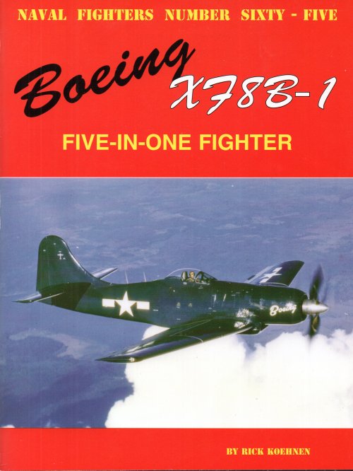
-Naval Fighters-Sixty.Five


Post-1
 

Attachments

  • Escanear0001.jpg
    Escanear0001.jpg
    425.4 KB · Views: 1,362
  • Escanear0007.jpg
    Escanear0007.jpg
    277.7 KB · Views: 559
  • Escanear0006.jpg
    Escanear0006.jpg
    180.6 KB · Views: 508
  • Escanear0005.jpg
    Escanear0005.jpg
    163 KB · Views: 1,085
  • Escanear0004.jpg
    Escanear0004.jpg
    214 KB · Views: 1,199
  • Escanear0003.jpg
    Escanear0003.jpg
    363.9 KB · Views: 1,347
  • Escanear0002.jpg
    Escanear0002.jpg
    302.3 KB · Views: 1,275
From
-Air enthusiast Nº55
-Le Fanatique de l'Aviation
-Airplane Five View Album B.C.F.Klein publications
-Warplanes of the Second World War-Volume Four
-Naval Fighters-Sixty.Five


Post-2
 

Attachments

  • Escanear0014.jpg
    Escanear0014.jpg
    146.4 KB · Views: 489
  • Escanear0013.jpg
    Escanear0013.jpg
    308.9 KB · Views: 498
  • Escanear0012.jpg
    Escanear0012.jpg
    130.7 KB · Views: 369
  • Escanear0011.jpg
    Escanear0011.jpg
    225.2 KB · Views: 384
  • Escanear0010.jpg
    Escanear0010.jpg
    323.3 KB · Views: 430
  • Escanear0009.jpg
    Escanear0009.jpg
    347 KB · Views: 403
  • Escanear0008.jpg
    Escanear0008.jpg
    374.2 KB · Views: 433
Topics merged. Please remember that the search engine is not very intelligent, so type the full designation "XF8B-1" next time...
 
Airtime Publishing's Classic Wings had a good article on this bird.
 
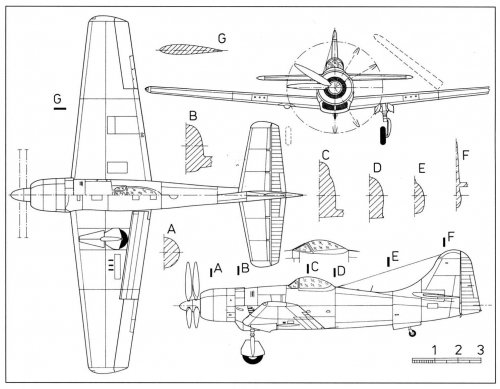
The drawing by Martin Salajka from Czech L+K magazine, No.5/1997:
 

Attachments

  • 1997-05_boeing_xf8b-1_draw.jpg
    1997-05_boeing_xf8b-1_draw.jpg
    160.6 KB · Views: 478
The F8B-1 is one of my personal favorites; because it's just so... audacious. Build a fighter around the biggest piston engine ever put into true mass production -- the R4360, and then demand that it fly a 850 nautical mile (!!) combat radius in the standardized late war fighter design mission with wing drop tanks and an internal bomb bay fuel tank.
 

Attachments

  • F8B-6.jpg
    734.3 KB · Views: 161
  • F8B-5.jpg
    782.1 KB · Views: 163
  • F8B-1.jpg
    1.3 MB · Views: 192
Splendid, Ryan! I like the F8B very much too. Jared's book on the subject is fantastic... Do you have it?
 

Attachments

  • XF-8B_1.jpg
    XF-8B_1.jpg
    87.5 KB · Views: 373
  • XF-8B_2.jpg
    XF-8B_2.jpg
    88.7 KB · Views: 312
  • XF-8B_3.jpg
    XF-8B_3.jpg
    91.3 KB · Views: 312
  • XF-8B_4.jpg
    XF-8B_4.jpg
    91.9 KB · Views: 370
I had put this up in the "Books" section thread on a book on this aircraft but perhaps these questions should also be posted up here.

Did the development of this aircraft go far enough for Deck-landing trials to be carried out? If so, then what were the results?

Thanks in advance.

Bigger Guns, MORE POWER!
B)
 
M. A. Rozon said:
Did the development of this aircraft go far enough for Deck-landing trials to be carried out? If so, then what were the results?

No. It was only tested ashore. Low speed handling was considered good and pilots thought there would be no reason why it would not have been entirely satisfactory operating from carriers. But the aircraft had various other problems, was over-weight, and the war was over. So the F8B was cancelled before much flying had been done.

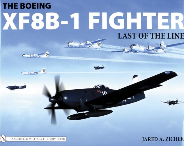
My source is the book XF8B-1 Fighter: Last of the Line by Jared A. Zichek (Schiffer, 2007).
 
I’m a bit a cooling and exhaust nerd, so this plane is surly interesting. Of course I also read about this plane here: https://oldmachinepress.com/2022/01/15/boeing-xf8b-five-in-one-fighter/ but the description sounds quite strange: “Engine cooling air was brought in the front of the cowling and expelled via cowl flaps around the upper part of the fuselage and slits for the exhaust stacks on the sides of the aircraft. The engine’s exhaust system was rather unusual and consisted of 14 exhaust stacks, with each stack serving two cylinders. On each side of the aircraft, four exhaust stacks were located in a slit behind the cowling. Another exhaust stack was forward of the slit and under the cowl flaps, and another stack protruded from the cowling forward of the cowl flaps. The last two stacks traveled through a passageway at the center of the scoop under the aircraft and expelled exhaust out of the bottom of the scoop.”

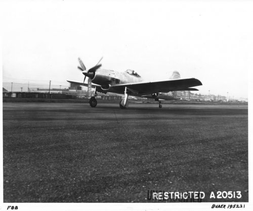
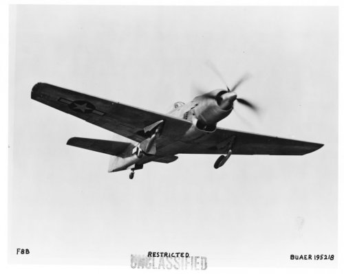
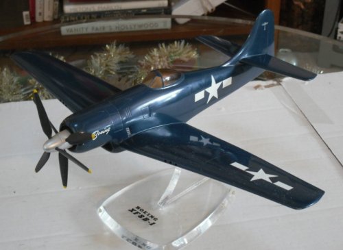
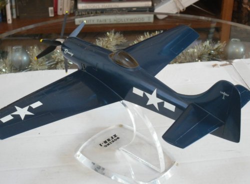
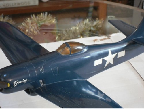
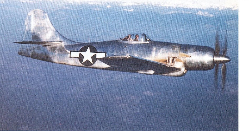
On the models and the photos, I couldn’t identify any exhaust at the bottom of the plane. On the sides, the arrangement is quite weird, there are indeed exhaust stakes in front of the side openings. The last pic in the first posting from Justo Miranda clearly shows some oil/soot tracks on the sides in front of the cooling outlets. This position doesn’t really fit very well, to the quite logic arrangement at the coolant openings, my idea is, that those might be a quick fix solution for a prototype.

The exhaust stacks at the cooling openings are in front of the coolant outlet, so that the cooling air will keep the exhaust gases away from the fuselage (well, not completely, as we see on the soot tracks). Unlike in the FW 190, no ejector effect is foreseen, but possible max. trust from the exhaust and minimized friction between the exhaust gases and the fuselage.

The exhaust openings at the bottom are also a quite strange arrangement:

“The last two stacks traveled through a passageway at the center of the scoop under the aircraft and expelled exhaust out of the bottom of the scoop.”

This would mean, that the hot exhaust pipes are crossing the cold air intake, I doubt that this is an ideal solution. For me, this is also an indication that something didn’t work out as planed and the exhaust system needed to be fixed by an improvised solution before something better could be implemented.
 
I’m a bit a cooling and exhaust nerd, so this plane is surly interesting. Of course I also read about this plane here: https://oldmachinepress.com/2022/01/15/boeing-xf8b-five-in-one-fighter/ but the description sounds quite strange: “Engine cooling air was brought in the front of the cowling and expelled via cowl flaps around the upper part of the fuselage and slits for the exhaust stacks on the sides of the aircraft. The engine’s exhaust system was rather unusual and consisted of 14 exhaust stacks, with each stack serving two cylinders. On each side of the aircraft, four exhaust stacks were located in a slit behind the cowling. Another exhaust stack was forward of the slit and under the cowl flaps, and another stack protruded from the cowling forward of the cowl flaps. The last two stacks traveled through a passageway at the center of the scoop under the aircraft and expelled exhaust out of the bottom of the scoop.”

On the models and the photos, I couldn’t identify any exhaust at the bottom of the plane. On the sides, the arrangement is quite weird, there are indeed exhaust stakes in front of the side openings. The last pic in the first posting from Justo Miranda clearly shows some oil/soot tracks on the sides in front of the cooling outlets. This position doesn’t really fit very well, to the quite logic arrangement at the coolant openings, my idea is, that those might be a quick fix solution for a prototype.

The exhaust stacks at the cooling openings are in front of the coolant outlet, so that the cooling air will keep the exhaust gases away from the fuselage (well, not completely, as we see on the soot tracks). Unlike in the FW 190, no ejector effect is foreseen, but possible max. trust from the exhaust and minimized friction between the exhaust gases and the fuselage.

The exhaust openings at the bottom are also a quite strange arrangement:

“The last two stacks traveled through a passageway at the center of the scoop under the aircraft and expelled exhaust out of the bottom of the scoop.”

This would mean, that the hot exhaust pipes are crossing the cold air intake, I doubt that this is an ideal solution. For me, this is also an indication that something didn’t work out as planed and the exhaust system needed to be fixed by an improvised solution before something better could be implemented.

Hmm, "hot exhaust pipes are crossing the cold air intake" - maybe not a big deal because R-4360 engine had intercooler?
 
It will reduce the mass flow for the compressor to the same degree as it would reduce the mass flow for a naturally aspirated engine. It would also increase the compressor outlet temperature even more, so that a higher compressor speed cant be used for compensation, most likely, it even would have to be decreased if the compressor outlet temperature is critical.
 
This thread reminded me I love this plane too, so just for the fun of it using Wikipedia I checked its weight and dimensions compared to a Skyraider and a Martin Mauler (not fighters, I know). And I can confirm: that thing was big and heavy.

https://en.wikipedia.org/wiki/Douglas_A-1_Skyraider
General characteristics
  • Crew: 1
  • Length: 38 ft 10 in (11.84 m)
  • Wingspan: 50 ft 0.25 in (15.2464 m)
  • Height: 15 ft 8.25 in (4.7816 m)
  • Wing area: 400.33 sq ft (37.192 m2)
  • Airfoil: root: NACA 2417; tip: NACA 4413[44]
  • Empty weight: 11,968 lb (5,429 kg)
  • Gross weight: 18,106 lb (8,213 kg)
  • Fuel capacity: 380 US gal (320 imp gal; 1,400 L) internal tanks
  • Powerplant: 1 × Wright R-3350-26WA Duplex-Cyclone 18-cylinder air-cooled radial piston engine, 2,700 hp (2,000 kW)
  • Propellers: 4-bladed Aeroproducts constant-speed propeller

https://en.wikipedia.org/wiki/Martin_AM_Mauler
General characteristics
  • Crew: 1
  • Length: 41 ft 3 in (12.57 m)
  • Wingspan: 50 ft 0 in (15.24 m)
  • Height: 16 ft 10 in (5.13 m)
  • Wing area: 496 sq ft (46.1 m2)
  • Empty weight: 15,257 lb (6,920 kg)
  • Gross weight: 25,737 lb (11,674 kg)
  • Fuel capacity: 510 US gallons (1,900 L; 420 imp gal)
  • Powerplant: 1 × Pratt & Whitney R-4360-4 Wasp Major Radial, 3,000 hp (2,200 kW)
  • Propellers: 4-bladed, 14 ft 8 in (4.47 m) diameter

https://en.wikipedia.org/wiki/Boeing_XF8B
General characteristics
  • Crew: 1
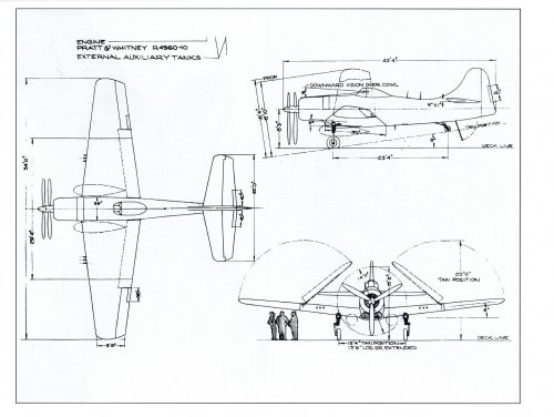
  • Length: 43 ft 3 in (13.18 m)
  • Wingspan: 54 ft (16 m)
  • Height: 16 ft 3 in (4.95 m)
  • Wing area: 489 sq ft (45.4 m2)
  • Empty weight: 13,519 lb (6,132 kg)
  • Gross weight: 20,508 lb (9,302 kg)
  • Max takeoff weight: 21,691 lb (9,839 kg)
  • Powerplant: 1 × Pratt & Whitney XR-4360-10 28 cylinder air-cooled piston engine, 3,000 hp (2,200 kW) for take-off; (3,600 hp (2,700 kW) war emergency with water injection)
  • Propellers: 3-bladed 2x Aeroprop, 13 ft 6 in (4.11 m) diameter contra-rotating co-axial propellers
 
I know all of the manufacturers had their "trademark" fin shapes back then, but in my opinion that B-17/B-29 tail just doesn't look right on a fighter...

...No matter how big the thing is!! ;)

Fascinating airplane, BTW. I can highly recommend the Ginter book for anyone who is interested in this beast.
 
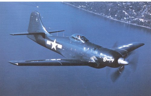
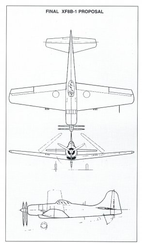
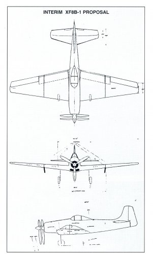
Boeing XF8B-1 Five-in One​


On June 30, 1941, the U.S. Navy Bureau of Aeronautics decided to support the development of the F7F Tigercat, a twin engine, single seat multirole heavy aircraft, to serve in the Midway class carriers.

The project was doomed to failure because with the technology available at the time, it was not possible to solve the problem of landing on the deck of an aircraft carrier with an engine stopped.

Early in 1943, the Bu Aer issued the specification SD-349, calling for a long-range shipboard escort fighter with 342 mph top speed, 79 mph landing speed, deck takeoff in 262 feet with 25 knot wind, 30,000 feet ceiling and 3,760 ft/min rate of climb.

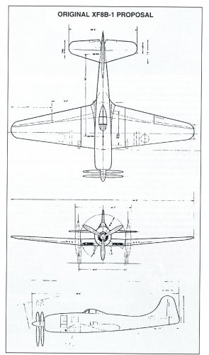
To avoid the symmetry problems suffered by the Tigercat, Boeing proposed to use a single engine aircraft designed to be used as long-range escort fighter, shorth range shipboard interceptor, high speed level bomber, medium range dive bomber or low level, medium range torpedo bomber.

To be able to perform such different roles, it was necessary to design a large airframe, 130 per cent heavier than a Hellcat and 116 per cent heavier than an Avenger to accommodate a large amount of fuel, fitted with vertically folding wings for carrier storage.

Tigercat designers calculated that its multirole missions required the power of two P&W R-2800-22W engines each rated at 2,200 hp, but the American industry had not been able to develop an operating engine of 4,400 hp and Boeing had to use the P&W R-4360 of only 3,000 hp. an experimental third-generation engine of which only a few prototypes had been built.

Boeing engineers took a big risk mixing an airframe with multiple innovative systems with a little-tested engine, and the predictable result was the construction of only three prototypes, no production contract and a program cost twice the estimate.

On April 10, 1943, the U.S. Navy awarded a contract for three prototypes (Bu Aer Nos. 57984, 57985 and 57986), one static test airframe, four engines, spares and design drawings.

The mockup of Boeing Model 400 was inspected in early October 1943.

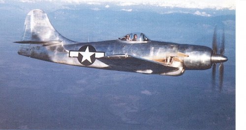
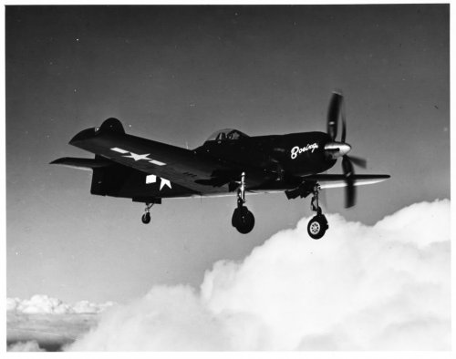
The first prototype was flown on November 27, 1944, powered by one Pratt and Whitney R-4360-8a, air cooled radial engine driving a six-bladed, contra-rotating airscrew Aeroproducts propeller.

This engine suffered from over speeding, overheating and it proved extremely hard to start, due carburetor malfunction.

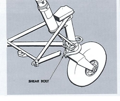
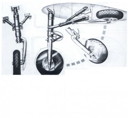
On February 13, 1945, during a 120-mph taxi run test, the undercarriage retracted without warning. As a result, the engine, the propeller, the chin air intake the landing gear doors and the bomb bay doors were damaged.

The aircraft was repaired, a new R-4360-10 engine (c/n 23) was installed, and a flight engineer's seat was located behind the pilot to reduce development time.

Between March 5 and April 9, 1945, the prototype was tested at Patuxent River naval air station, but the wing folding system proved not to work properly in moderate wind.

The U.S. Navy evaluation program included mockup combats against twin engine fighters Grumman F7F Tigercat and Bell P-59 Airacomet.

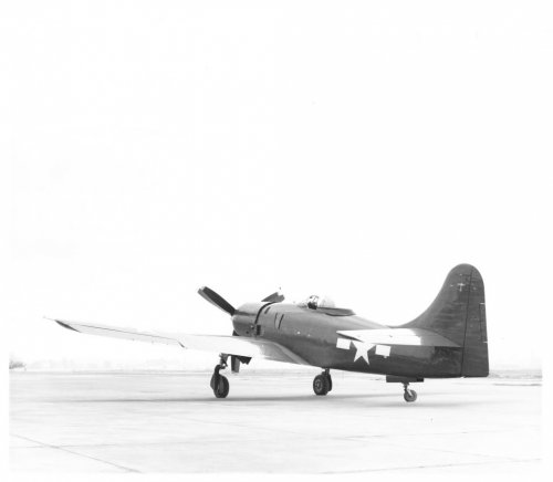
At this time the aircraft was not yet painted, except for a large Olive Drab anti-glare panel and four star and bars national insignia.

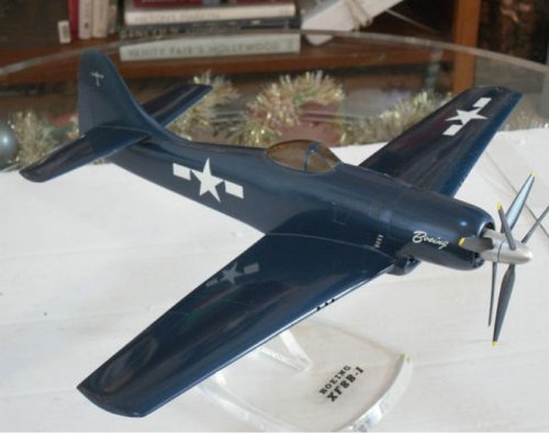
During the summer of 1946, the painting scheme was changed to overall Glossy Sea Blue (FS 15042, ANA 623).

First prototype technical data

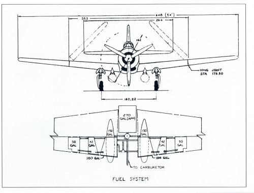
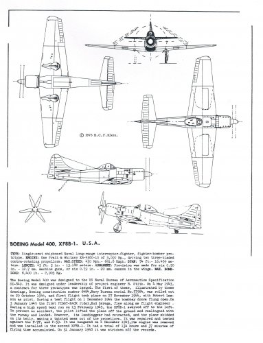
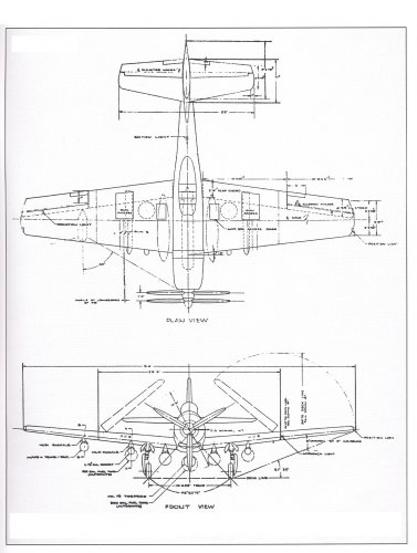
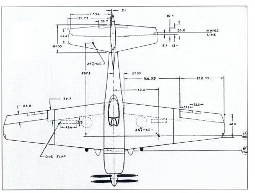
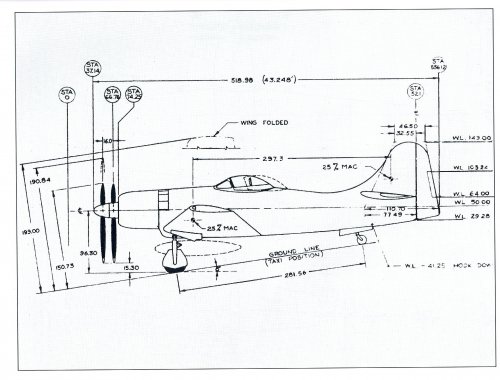
Wings: single spar, 16.46 m span, 45.43 sq. m area, electrically operated folding system and Fowler flaps, hydraulically boosted ailerons, 384 U.S. gallons of fuel housed in internal cells, 600 gallons in four underwing drop tanks and two underwing racks for 1,000 lb. bombs or two AD-1/AM-1 torpedoes, six 0.5-in machine guns with 400 rpg or six T-31 20-mm cannons with 200 rpg and main carriage members. In night fighter configuration, the plane could carry under the starboard wing one pod housing the AN/APS-4 airborne radar.

Fuselage: housing the engine mount, firewall, 40 U.S. gallon oil tank, chin air intake with the gun camera, cockpit with armor plates and bulletproof windshield, Mk 23 computing gunsight, bomb bay with four racks or one fuel cell containing 270 U.S. gallon, radio telephone, IFF radio, battery, landing lights, electrically operated tail wheel and tail hook, B-17 style tailfin and horizontal stabilizer with tabs, overall length: 13.21 m, height: 4.98 m.

Power plant: one Pratt and Whitney R-4360-10, 28 four row 28 cylinders, air cooled radial engine with two-stage engine-driven supercharger and intercooler, driving a six-bladed, contra-rotating Aeroproducts airscrew with 4.27 meters of diameter. The engine was rated at 3,000 hp, restricted to five minutes of max power.

Max weight: 10,414 kg, max speed: 695 km/h, service ceiling: 11,430 m, climb rate: 3,660 ft/min, range: 5,000 km.

The second prototype was flown on November 27, powered by the R-4360-10 (c/n 23) rebuilt after the accident of the first prototype.

On December 26, 1945, the aircraft suffered engine failure during a high-altitude flight test and the pilot was forced to make an emergency landing damaging the propeller.

It was also necessary to replace the engine with the R-4360-10 (c/n 31).

The second prototype was delivered to the USAF-Wright Field for an evaluation program conducted between February and August 1946.

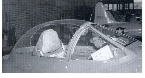
Several changes were incorporated at the request of the Air Materiel Command to increase the critical Mach number:

-Redesigned cockpit and canopy.

-Modified radio equipment.

-Revised exhaust tubes.

-Modified the carburetor air intake.

-Modified wheel covers.

-Faired tailhook.

-Installation of compressibility dive-recovery flaps.

As a result of all these modifications, the aircraft was 680 kg overweight.

The test program was terminated by a new engine failure and the prototype was returned to the Navy.

Painting scheme: Overall Glossy Sea Blue (FS 15042, ANA 623).


Proposed configurations to accomplish the various roles:

-Shipboard interceptor: with 384 U.S. gallons of fuel housed in the wing cells and six 0.5-in machine guns.

-Long-range escort fighter: with 384 U.S. gallons of fuel housed in the wing cells, 270 gallons in the bomb bay cell, 600 gallons in four underwing drop tanks and six 0.5-in machine guns.

-Medium range dive bomber: with 384 U.S. gallons of fuel housed in the wing cells, 270 gallons in the bomb bay cell, two 1,000 lb. bombs in underwing bomb racks and six 0.5-in machine guns.

-Long-range level bomber: with 384 U.S. gallons of fuel housed in the wing cells, 600 gallons in four underwing drop tanks, 3,200 lb. of internal bombs and six 0.5-in machine guns.

-Torpedo-bomber: with 384 U.S. gallons of fuel housed in the wing cells, 270 gallons in the bomb bay cell, three torpedoes AD-1 or AM-1 and six 0.5-in machine guns.

Tests showed that the aircraft did not excel at any of these roles.

Proposed production engines:

-P&W R-4360-B-2 with two-stage supercharger, rated at 3,250 hp.

-P&W R-4360-C with two-stage supercharger, rated at 3,500 hp.

The third prototype made its maiden flight in March 1946 powered by the engine c/n 31 and was used by the USAF for weapons tests at Eglin Field between July and December 1946.

When the machine guns were tested in flight, they were found to jam during maneuvers at high G and it was necessary to install anti-surge devices and ammunition drive boosters.

It was also shown that the poor design of the weapons housing caused inadequate cooling and led to frequent stoppages.

The 20-mm guns were not used during the tests.

The bomb bay doors were designed to open and close quickly after each bomb was launched and during testing of the system showed a tendency to open during tight turns, but they could not be bridled at more than 130 mph because of the negative air pressure. The launch system was never tested, only the external bomb racks were used for dive bombing tests.

During the tests, 1,000 lb. bombs were launched at 400 mph with diving angles between 40 and 60-degrees and 4-to-5 G pull outs.

The USAF evaluation concluded that the Model 400 was unsuitable for high-speed level bombing, because the deficient design of the bomb bay door system, also was unsuitable for diving due to its longitudinal instability diving at 60-degrees. The type proved inferior in dogfight against conventional fighters P-51 and P-47, due to their large size, overweight and slower maneuverability.

The U.S. Navy had considered a production contract for torpedo bombers, but the type was no better than the existing specialized torpedo bomber already available: Douglas BTD, Martin BTM and Curtiss BTC.

The Model 400 was too large compared to the Hellcat and Corsair naval fighters and took up too much space in the carrier's hangars, decreasing the number of aircraft available.

It was also unsuitable as a night fighter and the Navy preferred to use the Tigercat which could carry a larger, more advanced nose-mounted radar.

During the post war, the need for propeller fighters had disappeared and the last prototype was scrapped on March 16, 1950.

 

Attachments

  • 084.jpg
    084.jpg
    2 MB · Views: 95
Just read this from @Grey Havoc link:

Cooling air was directed through the oil coolers and out exit doors on the upper sides of the fuselage, just forward of the cockpit.
It does not bode well for the pilot in case of an oil cooling system failure. I mean, how many pilots died after their canopy was blacked out by spilling oil or were badly burned by hot fluid sprayed right into their faces...

I am sure there is more to enquire on this.
 
Last edited:
Awesome work, as usual, @Justo Miranda ! One question I've been willing to ask you for a while: with such a level of detail, notably on the paneling and rivets, is there a measure of guess work involved, and if so, how much so? Or is every detail accurate as per original company drawings? Thanks in advance for your answer.
 
Awesome work, as usual, @Justo Miranda ! One question I've been willing to ask you for a while: with such a level of detail, notably on the paneling and rivets, is there a measure of guess work involved, and if so, how much so? Or is every detail accurate as per original company drawings? Thanks in advance for your answer.
I have used many photos and construction schematics
 

Attachments

  • 476.jpg
    476.jpg
    405.1 KB · Views: 110
  • 477.jpg
    477.jpg
    345.6 KB · Views: 99
  • 478.jpg
    478.jpg
    563.6 KB · Views: 98
  • 479.jpg
    479.jpg
    999.5 KB · Views: 97
  • 480.jpg
    480.jpg
    871.2 KB · Views: 93
  • 481.jpg
    481.jpg
    842 KB · Views: 89
  • 482.jpg
    482.jpg
    486.3 KB · Views: 83
  • 483.jpg
    483.jpg
    967.4 KB · Views: 93
  • 484.jpg
    484.jpg
    1.1 MB · Views: 92
  • 487.jpg
    487.jpg
    1.5 MB · Views: 97
Post-2
 

Attachments

  • 488.jpg
    488.jpg
    1.9 MB · Views: 91
  • 489.jpg
    489.jpg
    562.6 KB · Views: 79
  • 490.jpg
    490.jpg
    235.5 KB · Views: 66
  • 491.jpg
    491.jpg
    210.1 KB · Views: 70
  • 492.jpg
    492.jpg
    881.2 KB · Views: 63
  • 493.jpg
    493.jpg
    568.2 KB · Views: 64
  • 494.jpg
    494.jpg
    228.4 KB · Views: 66
  • 495.jpg
    495.jpg
    294.6 KB · Views: 67
  • 496.jpg
    496.jpg
    953 KB · Views: 59
  • 497.jpg
    497.jpg
    327.4 KB · Views: 60
Post-3
 

Attachments

  • 498.jpg
    498.jpg
    445.4 KB · Views: 57
  • 499.jpg
    499.jpg
    312.1 KB · Views: 56
  • 500.jpg
    500.jpg
    699.3 KB · Views: 71
  • 501.jpg
    501.jpg
    1.8 MB · Views: 77
  • 502.jpg
    502.jpg
    301.7 KB · Views: 66
  • 503.jpg
    503.jpg
    461.5 KB · Views: 54
  • 504.jpg
    504.jpg
    248.7 KB · Views: 57
  • 505.jpg
    505.jpg
    4.6 MB · Views: 66
  • 506.jpg
    506.jpg
    145.6 KB · Views: 57
  • 507.jpg
    507.jpg
    1.2 MB · Views: 57
Post-4
 

Attachments

  • 508.jpg
    508.jpg
    156.4 KB · Views: 60
  • 509.jpg
    509.jpg
    392.4 KB · Views: 64
  • 510.jpg
    510.jpg
    2.8 MB · Views: 75
  • 511.jpg
    511.jpg
    2.6 MB · Views: 69
  • 512.jpg
    512.jpg
    1.8 MB · Views: 58
  • 513.jpg
    513.jpg
    1.1 MB · Views: 49
  • 514.jpg
    514.jpg
    943.7 KB · Views: 44
  • 515.jpg
    515.jpg
    711.5 KB · Views: 43
  • 516.jpg
    516.jpg
    585.6 KB · Views: 45
  • 517.jpg
    517.jpg
    323 KB · Views: 47

Similar threads

Back
Top Bottom