I’m a bit a cooling and exhaust nerd, so this plane is surly interesting. Of course I also read about this plane here:
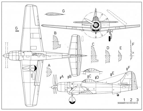
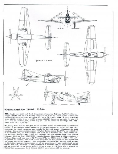
https://oldmachinepress.com/2022/01/15/boeing-xf8b-five-in-one-fighter/ but the description sounds quite strange: “Engine cooling air was brought in the front of the cowling and expelled via cowl flaps around the upper part of the fuselage and slits for the exhaust stacks on the sides of the aircraft. The engine’s exhaust system was rather unusual and consisted of 14 exhaust stacks, with each stack serving two cylinders. On each side of the aircraft, four exhaust stacks were located in a slit behind the cowling. Another exhaust stack was forward of the slit and under the cowl flaps, and another stack protruded from the cowling forward of the cowl flaps. The last two stacks traveled through a passageway at the center of the scoop under the aircraft and expelled exhaust out of the bottom of the scoop.”
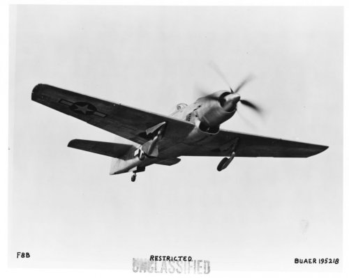
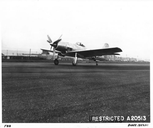
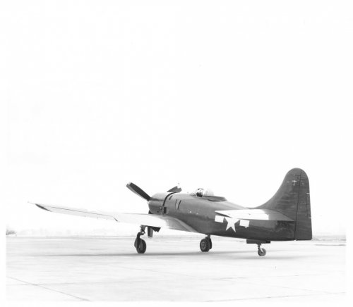
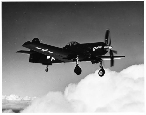
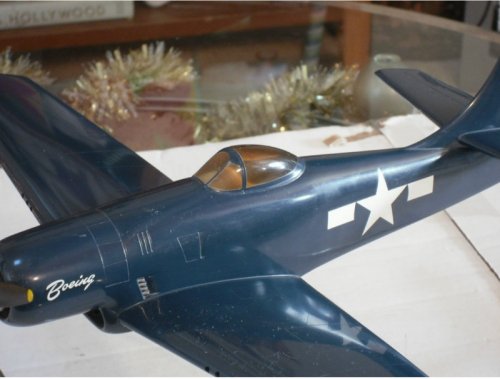
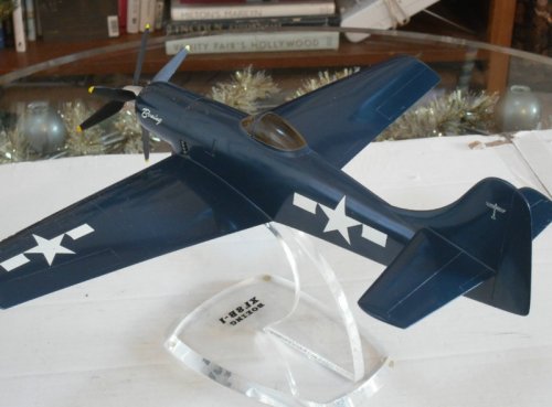
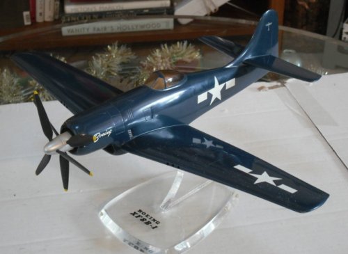
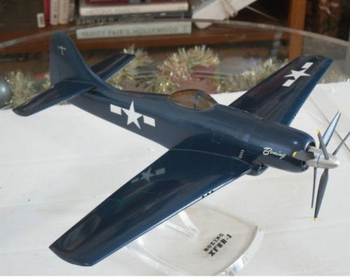
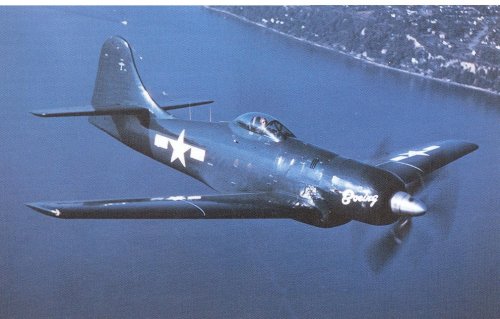
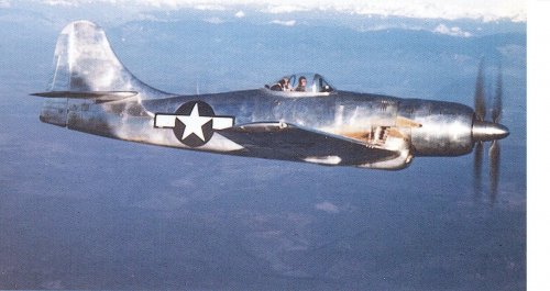
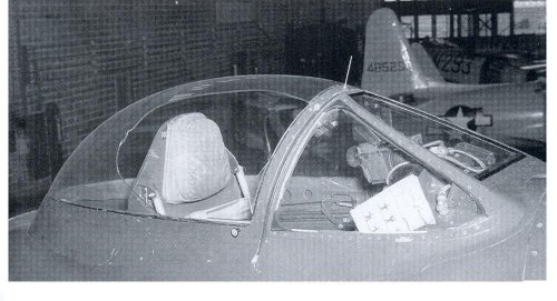
On the models and the photos, I couldn’t identify any exhaust at the bottom of the plane. On the sides, the arrangement is quite weird, there are indeed exhaust stakes in front of the side openings. The last pic in the first posting from Justo Miranda clearly shows some oil/soot tracks on the sides in front of the cooling outlets. This position doesn’t really fit very well, to the quite logic arrangement at the coolant openings, my idea is, that those might be a quick fix solution for a prototype.
The exhaust stacks at the cooling openings are in front of the coolant outlet, so that the cooling air will keep the exhaust gases away from the fuselage (well, not completely, as we see on the soot tracks). Unlike in the FW 190, no ejector effect is foreseen, but possible max. trust from the exhaust and minimized friction between the exhaust gases and the fuselage.
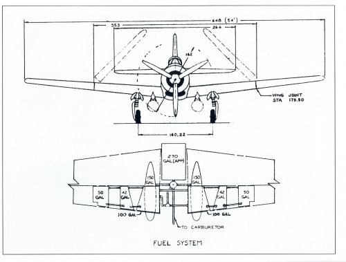
The exhaust openings at the bottom are also a quite strange arrangement:
“The last two stacks traveled through a passageway at the center of the scoop under the aircraft and expelled exhaust out of the bottom of the scoop.”
This would mean, that the hot exhaust pipes are crossing the cold air intake, I doubt that this is an ideal solution. For me, this is also an indication that something didn’t work out as planed and the exhaust system needed to be fixed by an improvised solution before something better could be implemented.

")