The fan "izd. 30" is called "izd. 129", one can timidly assume an air consumption of 129 kg/sec
The weight of the internal fuel T-50 is at least 9000 kg (according to 3-D modeling) or 10100 kg (according to an insider). The cruising flight speed according to the tactical and technical task is 1890 km / h, the flight time in this mode, according to the tactical and technical task is 1 hour. Therefore, the maximum flight range at supersonic speed is 1890 km (estimated) or 1500 km (according to Poghosyan)
Lets look at a similar sized engine, the F110-GE-129, with an airflow of 122.5 kg/sec and a FPR of 3.2, Sea Level Static Mil thrust of 17,155 lbs (7800 kg). If we ratio the airflow to 129 kg/sec and upmatch the FPR to the highest published value of 4.2 (EJ200) for supercruise performance, we get a first order approximation of 10780 kg for the izd 30 Mil SLS thrust. Assuming a 100F Theta break for full airflow / FPR at 1.5M (inlet conditions approximately 100F, 10psia at 40K), gives a supercruise thrust of 7300 kg. Giving credit for a world beating SFC of 0.70, you are burning approximately 5150 kg/hr x 2 engines= 10300 kg/hr.
You still have to take off and climb / accelerate to 40K, 1.5M, then RTB after the cruise portion. No way you have 1 hour of supercruise with the best case estimate of internal fuel. And it gets worse if the FPR / Mil Thrust levels are higher, or SFC is worse (likely for a supercruise engine), or your supercruise speed is higher.
The F-22 in fact seems to have two bleed/bypass mechanisms, one inboard of the forward section of the intake and one additional at the subsonic diffuser, close to the engine inlet. I don't know if the first one is for the boundary layer extraction and the other the proper bypass door? With a fixed intake, there must indeed be some compensating mechanisms to ensure stable air supply to the engine across the whole flight envelope.
The variable intake is inherently superior in performance across a wider range of speeds and altitudes, but I know and I agree that the fixed intake design of the F-22 is most likely optimized for the flight regime considered most vital, probably max cruising speed. BTW, do you know how many shocks does the F-22 intake generate? And why can't fixed intakes be designed for speeds above 2 M, would they be too inefficient at lower speeds?
The F-22 intake does have a boundary layer splitter from the forward fuselage, boundary layer bleed perforations in parts of the intake forward of the throat, and the airflow bypass louvers in front of the engine inlet.
I don't have any engineering specifics on how many shocks the F-22 inlet generates, but visually it appears that there is a single ramp angle on both the inner lip and the upper lip, both generating a single oblique shock prior to the throat normal shock. I don't know if having crossing oblique shocks from two sides of the intake is more efficient than the traditional 2D single oblique (F-15, F-14), but I have read the a center cone (SR-71) or half cone (F-104) making a circular oblique shock has lower shock intensity (lower losses) than a 2D oblique shock
The Russian textbook "Forecasting the development of aviation technology" provides calculations of fighters with supersonic cruising speed. The fighter with a mass of about 25 tons and a fuel weight of 8 tons has a subsonic range of 3,400 km and a supersonic range of 1,500 - 1,700 km . Su-57 with the same weight has a fuel reserve of 9 - 10 tons
The Russian textbook "Forecasting the development of aviation technology" provides calculations of fighters with supersonic cruising speed. The fighter with a mass of about 25 tons and a fuel weight of 8 tons has a subsonic range of 3,400 km and a supersonic range of 1,500 - 1,700 km . Su-57 with the same weight has a fuel reserve of 9 - 10 tons
It is 2x - both engines are consuming fuel, aren’t they?
Supercruise inlet conditions for the engine is not much different than sea level hot day, so you will burn fuel at a similar rate. If you go higher, the ambient and engine inlet pressures will be lower, so fuel flow and thrust will both be lower, along with drag, so maybe if you maintain your supercruise at 55-60k ft, your cruise distance will increase. But it takes more fuel to reach that cruise condition.
If you include air to air refueling to top off the tanks before starting the high speed cruise, that would mitigate the takeoff and climb consumption, but airborne tankers are not a Russian strength.
Lets look at a similar sized engine, the F110-GE-129, with an airflow of 122.5 kg/sec and a FPR of 3.2, Sea Level Static Mil thrust of 17,155 lbs (7800 kg). If we ratio the airflow to 129 kg/sec and upmatch the FPR to the highest published value of 4.2 (EJ200) for supercruise performance, we get a first order approximation of 10780 kg for the izd 30 Mil SLS thrust.
Sorry for the silly question. Can you clarify why the increase in FPR increases linearly the thrust? Is it increasing the mass flow in the same rate or is it related to exhaust velocity? That first order approximation means you are disregarding the jet velocity increase?
Uninstalled mil thrust in the izd. 30 should be rather close to 12 t (at least), if the specific thrust is higher than that of the F119, but I get yours was simply an example.
Assuming a 100F Theta break for full airflow / FPR at 1.5M (inlet conditions approximately 100F, 10psia at 40K), gives a supercruise thrust of 7300 kg. Giving credit for a world beating SFC of 0.70, you are burning approximately 5150 kg/hr x 2 engines= 10300 kg/hr.
Is such a thrust necessary for supersonic flight at that speed? Is that altitude the optimum in your opinion?
From the MiG-31's supersonic range (1500 km, with 16 t fuel but cruising on AB) I assume the thrust required is substantially lower. The aero design of the Su-57 seems particularly well suited for very high ceiling, strikingly it does not normally deploy flaps even for very short take off runs...
You still have to take off and climb / accelerate to 40K, 1.5M, then RTB after the cruise portion. No way you have 1 hour of supercruise with the best case estimate of internal fuel. And it gets worse if the FPR / Mil Thrust levels are higher, or SFC is worse (likely for a supercruise engine), or your supercruise speed is higher.
Agreed, at that thrust there is no way one hour supersonic flight can be realistically maintained. But the 1500 km apparently stated by Pogosyan are feasible I think (based on what the MiG-31 can do), at least when not at max cruising speed.
I don't have any engineering specifics on how many shocks the F-22 inlet generates, but visually it appears that there is a single ramp angle on both the inner lip and the upper lip, both generating a single oblique shock prior to the throat normal shock. I don't know if having crossing oblique shocks from two sides of the intake is more efficient than the traditional 2D single oblique (F-15, F-14), but I have read the a center cone (SR-71) or half cone (F-104) making a circular oblique shock has lower shock intensity (lower losses) than a 2D oblique shock
That would be apparently one 3D oblique shock and a normal one. As the F-22, the Su-57 also has 3D type of oblique shock due to the low RCS design of the intakes, but due to the variable ramps configuration it is a 4 shock design.. I have seen diagrams showing the compared pressure recovery as a function of the number of shocks, I don't know to what extent they are generally applicable. The difference seems to be in the single digit percentages for speeds between 1.5 and 2 M, afterwards it grows rather fast. Further supporting that Sukhoi had important reasons to give the plane a max speed above 2 M.
Supercruise inlet conditions for the engine is not much different than sea level hot day, so you will burn fuel at a similar rate. If you go higher, the ambient and engine inlet pressures will be lower, so fuel flow and thrust will both be lower, along with drag, so maybe if you maintain your supercruise at 55-60k ft, your cruise distance will increase. But it takes more fuel to reach that cruise condition.
As said above, what is not clear is that such a high thrust is needed to keep 1.5 M, you surely know but I take that you probably cannot go into details. Apart from the investment in reaching that altitude, does anything make more recommendable to fly lower, from the propulsion perspective? Or is rather an aero/lift issue? The more you fly at high altitude, the more fuel you save, the longer your missiles will fly, even the aero of incoming AAMs is going to be challenged when they need to turn for a kill. On top of that, a higher speed can be achieved, since the ram compression will help (intake conditions will be equivalent at different speeds for different flight altitude)
A high flying plane with low g generation capacities can find itself in difficulties if it needs to outrun a missile despite being very fast (i.e. MiG-31), but the Su-57 seems to have a design capable of generating a lot of lift and it is not only highly unstable, but the LEVCONS can be deflected slightly upwards, a feature that should allow to compensate the shifting in the center of lift at supersonic speed and keep a nose up attitude that will further help turning. So, why should it not fly as high as possible and save as much fuel as possible?
Lets look at a similar sized engine, the F110-GE-129, with an airflow of 122.5 kg/sec and a FPR of 3.2, Sea Level Static Mil thrust of 17,155 lbs (7800 kg). If we ratio the airflow to 129 kg/sec and upmatch the FPR to the highest published value of 4.2 (EJ200) for supercruise performance, we get a first order approximation of 10780 kg for the izd 30 Mil SLS thrust.
Sorry for the silly question. Can you clarify why the increase in FPR increases linearly the thrust? Is it increasing the mass flow in the same rate or is it related to exhaust velocity? That first order approximation means you are disregarding the jet velocity increase?
Uninstalled mil thrust in the izd. 30 should be rather close to 12 t (at least), if the specific thrust is higher than that of the F119, but I get yours was simply an example.
Increasing the Fan Pressure Ratio increases the Nozzle Pressure Ratio, which increases exhaust velocity and thrust, with no change in total airflow.
I am assuming a linear relationship between FPR and thrust as a first order approximation for Sea Level Static thrust. It is more complicated than this for SLS thrust, and definitely not linear for supercruise thrust. For example, if my baseline engine with a FPR of 3.2 has a exhaust velocity of 1000 mph (that is a wild ass guess for this example) while flying at 1000 mph at 40K, it will have zero thrust even though it is still consuming fuel at the similar rate as SLS. Push the FPR up to the 4.2 level of the example, now the exit velocity is 1300 mph (another WAG) and you have positive thrust at that condition. Remember that thrust = mass flow multiplied by the change in velocity from the inlet to the exhaust
But, as you noted, this was just an approximation to see if 10,000 kg of fuel could get you 1 hour of supercruise with two 129 kg/sec airflow, high FPR engines
As for the izd. 30, if they can achieve a higher specific thrust at supercruise conditions than the F119 with any sort of durability, they will have accomplished quite a feat.
Agreed that a variable multiple shock inlet can have higher inlet pressure recovery than a normal shock or fixed ramp single oblique shock inlet as you go faster, with the difference getting greater with increasing Mn beyond 1.5. But, I have read elsewhere that the Su-57 will be limited to 2.2 Mn due to heating of the airframe composite structure, so you have to balance the weight and complexity of the variable inlet against the benefit that will only be realized in the far right side of the flight envelope that is seldom used in tactical fighters.
Increasing the Fan Pressure Ratio increases the Nozzle Pressure Ratio, which increases exhaust velocity and thrust, with no change in total airflow.
I am assuming a linear relationship between FPR and thrust as a first order approximation for Sea Level Static thrust. It is more complicated than this for SLS thrust, and definitely not linear for supercruise thrust. For example, if my baseline engine with a FPR of 3.2 has a exhaust velocity of 1000 mph (that is a wild ass guess for this example) while flying at 1000 mph at 40K, it will have zero thrust even though it is still consuming fuel at the similar rate as SLS. Push the FPR up to the 4.2 level of the example, now the exit velocity is 1300 mph (another WAG) and you have positive thrust at that condition. Remember that thrust = mass flow multiplied by the change in velocity from the inlet to the exhaust
Ok many thanks, now a few things are making sense. That increase of jet velocity did not seem even close to be linear to me and that got me confused.
Now you explain the exhaust velocity issue and given the thrust is reduced so fast as the plane's speed increases, I guess there is a point where AB is probably needed to reach enough exhaust speed to actually generate thrust, though I assume this limit shifts as the engines increase their operational temperature with each generation. Do you know where the rough limit for the current crop of engines would be, and how this may change as TIT increases? So, what would be the limit for a supercruising aircraft, if other effects like fuselage limits where not considered?
Also related to this explanation and to address something that I may be misunderstanding, how would you create an engine with the same compressor diameter but much higher mass flow? I understand that first of all the RPM should increase, but not necessarily the max FPR, is that correct?
As for the izd. 30, if they can achieve a higher specific thrust at supercruise conditions than the F119 with any sort of durability, they will have accomplished quite a feat.
They talk about the original AL-41F (the big engine developed for the MFI more or less at the same time the F119 was) as 5th gen. Since then, the state of the art moved from 3000F TIT (public available estimation, don't know if this has been said officially at anytime) on the
F119 to 3600F on the F135 which is, unless I am very wrong, essentially a F119 core with different LPC/BPR and one additional LPT stage. They even say the F135 has reserve to produce more than 50,000 lbf, so it sounds reasonable to me that the increase in thermal efficiency alone should allow for an engine whose creators define as gen 5+ or even 5++ to reach higher specific thrust than the already mature F119 without any disruptive technology.
Them taking their sweet time for the development and testing makes sense when the point you make re. durability is considered. The core will be used for most of the next military engines so it cannot be a boutique item. They claimed substantial increase in operational life and time between overhauls, not sure if regarding the original AL-31F or vs the izd. 117.
Agreed that a variable multiple shock inlet can have higher inlet pressure recovery than a normal shock or fixed ramp single oblique shock inlet as you go faster, with the difference getting greater with increasing Mn beyond 1.5. But, I have read elsewhere that the Su-57 will be limited to 2.2 Mn due to heating of the airframe composite structure, so you have to balance the weight and complexity of the variable inlet against the benefit that will only be realized in the far right side of the flight envelope that is seldom used in tactical fighters.
Yeah, there were even official statements about the speed of the plane being reduced to 2 M in order to avoid reinforcement of the keels. But was that cruising or top speed? What is the point of heavier, more complex intakes which only are needed between 2 and 3 M, if the plane flies slower? I need to take those statements about the max speed of the plane with caution, something does not add up.
Increasing the Fan Pressure Ratio increases the Nozzle Pressure Ratio, which increases exhaust velocity and thrust, with no change in total airflow.
I am assuming a linear relationship between FPR and thrust as a first order approximation for Sea Level Static thrust. It is more complicated than this for SLS thrust, and definitely not linear for supercruise thrust. For example, if my baseline engine with a FPR of 3.2 has a exhaust velocity of 1000 mph (that is a wild ass guess for this example) while flying at 1000 mph at 40K, it will have zero thrust even though it is still consuming fuel at the similar rate as SLS. Push the FPR up to the 4.2 level of the example, now the exit velocity is 1300 mph (another WAG) and you have positive thrust at that condition. Remember that thrust = mass flow multiplied by the change in velocity from the inlet to the exhaust
Ok many thanks, now a few things are making sense. That increase of jet velocity did not seem even close to be linear to me and that got me confused.
Now you explain the exhaust velocity issue and given the thrust is reduced so fast as the plane's speed increases, I guess there is a point where AB is probably needed to reach enough exhaust speed to actually generate thrust, though I assume this limit shifts as the engines increase their operational temperature with each generation. Do you know where the rough limit for the current crop of engines would be, and how this may change as TIT increases? So, what would be the limit for a supercruising aircraft, if other effects like fuselage limits where not considered?
Also related to this explanation and to address something that I may be misunderstanding, how would you create an engine with the same compressor diameter but much higher mass flow? I understand that first of all the RPM should increase, but not necessarily the max FPR, is that correct?
For a given NPR, the exit Mach number will remain the same, but speed of sound goes up with increasing exhaust temperature. The basic relationship Vexhaust = V(speed of sound standard day) x √Theta(exhaust temp) x Mn(exhaust). So the exhaust velocity, at a given NPR, goes up with the square root of the exhaust temperate increase. If you had an exhaust velocity of 1000 mph with a exhaust temperature of 1000R, and then increase the exhaust temperature to 4000R (i.e. afterburner), your exhaust velocity would go up to 2000 mph. Increasing Mil power exhaust temperature does increase exhaust velocity, but this is a relatively shallow slope because of the square root relationship.
Just because TIT increases does not mean exhaust temperature increases, depending on the design of the engine. One with a higher OPR and bypass ratio would mean that you are extracting more work from the core exhaust stream to drive the fan, lowering that turbine exit temperature along with additional cool fan bypass air mixing in. Remember, although raising exhaust temperature can increase thrust, that extra exhaust temperature represents waste heat, to the detriment of SFC.
It is very difficult to significantly increase mass flow without increasing the fan diameter. You can make the inner diameter of the fan smaller to increase the flow area, but that inner area has lower blade velocity and doesn't do much work. You can cheat a little like the F110 engine that was designed to fit the F-15 / F-16 inlet duct - the front OD edge of the fan case is forward of the nose cone and the flow path is bulged out at the tips of the blades, giving a larger area fan mated to a smaller duct. But the smaller duct limits just how much air can pulled into the engine.
There is much more to supersonic drag than simply the wing sweep. The YF-23 is a superior aircraft in supercruise compared to the YF-22, despite the latter also having a 48 degree wing sweep.
Manufacturers and designers can make claims about their goals, but until it is demonstrated with solid numbers I wouldn’t take qualitative statements as gospel one way or another.
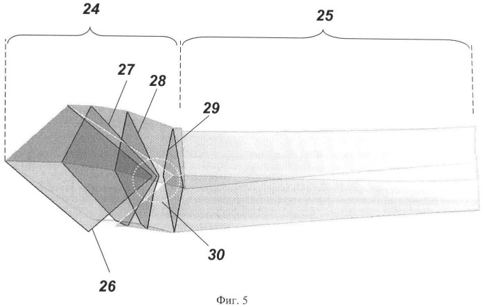
From the patent RU 2472956, maybe such solution is already present?
Stable operation of the air intake in all flight modes and engine operation is provided due to the presence of an air bypass in oblique jumps of the seal 28, a system for draining the boundary layer in the form of perforations on the stages of wedges 7 and 20 of the braking system and a transverse gap 13 between the front 11 and rear 12 adjustable panels. Draining of the boundary layer is additionally possible through an additional transverse slot, which is regulated by the flap 21 and located in the throat area behind the stationary braking wedge 20, which contains unregulated steps.
No, it’s not the same. From what I can tell from the patent, the passage describes the methods for absorbing the boundary layer, as well as control of spillage at station 28, which is the lower outboard corner of the inlet. The variable ramps of the Su-57 inlet can help ensure that inlet operation is closer to critical, and better avoid buzz instability that can occur at sub-critical conditions. “Station 28” is not the same as the bypass louvres as seen on the F-22’s inlet, as those are well downstream of the throat. Instead of variable ramps, the F-22 inlet uses a pressure system to control the positions of the two oblique shocks from the upper inboard corner, ahead of the terminal shock at the throat. The two inlet designs are different methods of ensuring efficient supersonic operation, and shouldn’t be compared with each other in isolation.
Regarding estimates of mass flow, to be frank these seem more to be what you aspire, rather than any solid numbers. Trying to correlate nominal maximum afterburning thrust (nominal numbers that may not even reflect the same methods of measurement) with mass flow between different families of engines is futile. Currently there simply isn’t anything to make definitive statements of mass flow between the F119, AL-41F1, or the izdeliye 30 one way or another.
Regarding that mass flow number you threw up, that’s comparable to the mass flow rate of the F135, an engine with a 43 in (1.092 m) inlet diameter, compared to the AL-41F1S inlet diameter of 36.7 in. Are you out of your mind?
LMFS said:
contrary to the usual Russian philosophy of making sure every piece of HW does not have significant weak spots and is capable of holding its own vs. diverse types of threats
That’s not a design “philosophy” of any kind, Russian or otherwise. Reading about the history of the PAK FA program since its inception would allow for better understandings of the intents and goals, which is very different from the ATF; it was not designed as a specific “counter”.
Increasing Mil power exhaust temperature does increase exhaust velocity, but this is a relatively shallow slope because of the square root relationship.
Just because TIT increases does not mean exhaust temperature increases, depending on the design of the engine. One with a higher OPR and bypass ratio would mean that you are extracting more work from the core exhaust stream to drive the fan, lowering that turbine exit temperature along with additional cool fan bypass air mixing in. Remember, although raising exhaust temperature can increase thrust, that extra exhaust temperature represents waste heat, to the detriment of SFC.
Yes, the scenario here was comparing supercruising engines (main focus on specific thrust) designed as per current state of the art vs. engines half a generation earlier.
Re. the SFC remark, it was interesting that Marchukov talked about 5th gen engines having an additional cardinal parameter, the SFC at supersonic cruising. And in that context, the mention to the fact that the izd. 30 keeps the same fuel consumption of the AL-31F means highly probably at optimal conditions in subsonic cruising, while the values at supersonic cruise will be probably widely different. First because of the thrust decrease of the engine at higher speed, second, in case a variable BPR is the feature of the engine that enables low SFC and high spec. thrust. I don't know if that makes sense to you, this is the key, thorny question about the izd. 30 that interestingly I have never seen analysed seriously, despite the existing evidence.
It is very difficult to significantly increase mass flow without increasing the fan diameter. You can make the inner diameter of the fan smaller to increase the flow area, but that inner area has lower blade velocity and doesn't do much work. You can cheat a little like the F110 engine that was designed to fit the F-15 / F-16 inlet duct - the front OD edge of the fan case is forward of the nose cone and the flow path is bulged out at the tips of the blades, giving a larger area fan mated to a smaller duct.
Wouldn't a increase in the fan speed increase the flow? Maybe also aero design of the compressor helps. At the end of the day mass is one of the two factors of thrust and is nearly always is increased in each upgraded or new design. The izd. 30 should fit in the same existing airframe and therefore I assume both the max external diameter and the intake/inlet duct design should remain roughly the same, maybe adjustments are possible but probably not very big after ten years of testing the T-50
In any case the F110 trick you mention is very interesting. The izd. 30 is said to have a layout of 3 LPC/5 HPC/1 HPT/1 LPT, that is, significantly less stages than the previous AL-31F family and therefore it may be possible to apply that recessing of the nose cone a bit backwards. Or would one expect the blades of the new stages to have significantly lower aspect ratio and therefore to occupy proportionally more length? Would that increase the efficiency of the compressor in any way?
In the case of the Su-57, the decision of creating a second stage engine was taken very early in the development, so it is thinkable that some headroom was left purposefully for engine upgrade. That is why I was willing to use the intake size as an element of analysis, considering it needs to be properly matched under criteria similar to those of other existing designs.
I don’t see this type of inlet airflow bypass in the Su-57, unless the auxiliary inlets under the variable ramp section can function in this capacity at supersonic speeds. This might imply a lower supercruise target speed for this design, perhaps in the 1.2-1.3M range. This also would lower the inlet temperature to the engine, making a high Theta break less important.
Have you ever wondered why the Su-57 has a large sweep wing, 48 degrees? This is more than any other fighter
The Russian Air Forces required a cruising speed of M>1.78 (1900 km/h) from a fifth-generation fighter
Manufacturers and designers can make claims about their goals, but until it is demonstrated with solid numbers I wouldn’t take qualitative statements as gospel one way or another.
No-one demonstrates anything in the field of state of the art military equipment, we just get rough info and vague claims. So you can either try to make educated guesses and estimations or close 80% of the board discussions, we are neither trying to write PhDs here nor getting barely decent data for analysis to start with.
No, it’s not the same. From what I can tell from the patent, the passage describes the methods for absorbing the boundary layer, as well as control of spillage at station 28, which is the lower outboard corner of the inlet.
Yes it is clearly not the same, but from the wording it seemed to have a similar function, not related to extracting the boundary layer as the rest of the elements. So how is this to be understood, the four shocks change according to the inlet conditions, allowing that lower outboard corner of the intake to spill more or less air?
the F-22 inlet uses a pressure system to control the positions of the two oblique shocks from the upper inboard corner, ahead of the terminal shock at the throat.
Trying to correlate nominal maximum afterburning thrust (nominal numbers that may not even reflect the same methods of measurement) with mass flow between different families of engines is futile.
I know your opinion (i.e. no analysis should be allowed about anything you don't like) and I have told you that I don't buy it. So why do you insist?
Explain at least where the thrust difference comes from, if supposing an equal or higher mass flow for greatly increased thrust is so crazy You know my take is way more reasonable than flat out dismissing higher mass flow.
For that thrust gain it is necessary more mass, and/or more exhaust speed, which in turn is tightly locked to fuel burn temperature, analogous nozzle performance, very similar engine layouts and goals, similar state of the art, almost same size. The only possibility I can come up with is that izd. 30 is a VCE and in high BPR mode it can direct more fresh air to the AB than the relatively low BPR F119, it would need to gain a very substantial advantage in exhaust velocity (jet temperature ca. 20-30% higher in AB if we take both engines have the same mass flow) to reach such difference in max thrust. Do you see that more likely?
No-one demonstrates anything in the field of state of the art military equipment, we just get rough info and vague claims. So you can either try to make educated guesses and estimations or close 80% of the board discussions, we are neither trying to write PhDs here nor getting barely decent data for analysis to start with.
…
I know your opinion (i.e. no analysis should be allowed about anything you don't like) and I have told you that I don't buy it. So why do you insist?
The conclusion that you are trying to reach requires information that is not available. Even these estimates require so much supposition and assumptions that, with any reasonable margin of error, they are useless in terms of making a qualitative comparison of one system to another. It doesn’t take a PhD dissertation to see that.
Sure, you can analyze, but the types of assertions that you’re making with your analysis, i.e. comparison of mass flow rate numbers, pressure recovery across the envelope, etc. are not provable. You’re trying to assert the superiority of one system to another, but they depend on such vague estimate with so much margin of error that it simply cannot demonstrate what you want to claim with any kind of rigor.
Yes it is clearly not the same, but from the wording it seemed to have a similar function, not related to extracting the boundary layer as the rest of the elements. So how is this to be understood, the four shocks change according to the inlet conditions, allowing that lower outboard corner of the intake to spill more or less air?
…
Two shocks, does it have two different wedge angles? They are not so easy to discern. Is it a three shock intake then?
As to the pressure system, is that active or passive? Do you have more info about that?
The inlets need to ensure that flow conditions are matched to the engine’s operations. Excess air can be bled through louvres, be spilled in front of the cowl, or bled through the opening between the front and rear ramps of the duct.
Regarding the F-22’s caret inlets, as F119Doctor said, the engineering specifics aren’t available, so I can’t answer how exactly the pressure system works. The caret surface is highly swept in two axes, thus generating a pair of 3D oblique shocks and based on literature that’s available, at the optimal design point, these pairs of shocks become nearly co-planar. Note that the equations for 3D oblique shocks are somewhat different from 2D and have more variables.
Regarding the F-22’s caret inlets, as F119Doctor said, the engineering specifics aren’t available, so I can’t answer how exactly the pressure system works. The caret surface is highly swept in two axes, thus generating a pair of 3D oblique shocks and based on literature that’s available, at the optimal design point, these pairs of shocks become nearly co-planar. Note that the equations for 3D oblique shocks are somewhat different from 2D and have more variables.
Ok I see, I assume those coplanar shocks could be considered one of the 3D shocks according to the patent drawings of the Su-57 above. But it indeed seems true that with varying speed they would stop being coplanar...
What’s interesting is that the shocks as described in the patent correspond to the ramps in a manner similar to the 2D variable inlets as seen on the F-15 and Su-27. Perhaps the sweep angle along the horizontal axis is too shallow for a shock to remain attached? This is difficult to determine without knowing the local flow field around the inlet.
The diagram showing the trend of the number of shocks versus pressure recovery appears to depict mixed compression inlets. Given the risk of unstarts, I’m skeptical that a mixed compression inlet would be employed in a fighter aircraft that will transition rapidly within its envelope.
Supersonic intakes with auxiliary inlets or high capacity spill doors seems to be almost a philosophical difference between US and Russian manufacturers, with the Russians preferring to bleed overboard as little as possible. If you're able to ensure the resulting smaller intake aperture performs at low Mach and high AoA (as the Russians have exhaustively demonstrated they can) I'm inclined to agree with the Russian approach. It should result in a less voluminous duct and therefore a slightly more slender and lighter aircraft.
What’s interesting is that the shocks as described in the patent correspond to the ramps in a manner similar to the 2D variable inlets as seen on the F-15 and Su-27. Perhaps the sweep angle along the horizontal axis is too shallow for a shock to remain attached? This is difficult to determine without knowing the local flow field around the inlet.
Yes, there is a clear Su-27 heritage, it's basically a hybrid between the F-22 and Flanker designs. Fixed inboard ramps (though the F-22 has isentropic compression surfaces instead of distinct ramps, as I understand) combined with Su-27 style variable upper ramps and auxiliary gills. Due to their variability, the upper ramps dominate (the inboard wedge angles are much shallower) compared to the more "symmetrical" F-22.
The diagram showing the trend of the number of shocks versus pressure recovery appears to depict mixed compression inlets. Given the risk of unstarts, I’m skeptical that a mixed compression inlet would be employed in a fighter aircraft that will transition rapidly within its envelope.
Only the 4-shock and upper 3-shock examples, and for the purpose of a first-order total pressure recovery comparison the implementation is irrelevant anyway - it's the bare number of shocks that is decisive. What a mixed compression intake has going for it is smaller projected frontal area and hence lower cowl drag, which becomes a big consideration as increasing numbers of shocks add up to a high flow deflection angle. As you say the stability control problem makes them poorly suited to fighter aircraft though.
If looking at the letter "F" we consider the F-117 a fighter, then yes. Such a sweep of the wing in this case was chosen for reasons of a smaller RCS.
Operational overload of Su-57 9 - 9.5 g, F-117 - 6 g. It is obvious that a straight wing is more suitable for better maneuverability
Regarding Su-57 inlets, I do wonder why the auxiliary inlets are a rectangular mesh rather than the serrated openings like the F-22’s louvres in reverse. Now, on the subject of bleeding excess air, in the F-14 inlet, the gap between the converging and diverging ramps appears to have a bleed air function, and perhaps the Su-57 uses a similar principle.
I’m also not sure if the two compression ramps on the F-22 are considered isentropic. They’re angled roughly “symmetrically” but isentropic ramp geometries are generally at least second order polynomial; of course, this can be difficult to discern visually.
Regarding Su-57 inlets, I do wonder why the auxiliary inlets are a rectangular mesh rather than the serrated openings like the F-22’s louvres in reverse.
Same here! When I doodled a "Su-57M" with stage II engines and improved stealth, that (plus getting rid of the variable ramps, assumption being that they were attributable to the interim engines) was one of the changes!
Now, on the subject of bleeding excess air, in the F-14 inlet, the gap between the converging and diverging ramps appears to have a bleed air function, and perhaps the Su-57 uses a similar principle.
It almost certainly does, since that is how the Su-27 handles it as well (again bearing in mind the close resemblance in many other respects). Only on the Flanker (and by extension the Su-57) the excess flow is moderate enough to be dumped via the BL bleed system, without dedicated spill doors (or a variable area outlet as on the F-14).
I’m also not sure if the two compression ramps on the F-22 are considered isentropic. They’re angled roughly “symmetrically” but isentropic ramp geometries are generally at least second order polynomial; of course, this can be difficult to discern visually.
Neither am I, to be frank - but I've seen the claim made by knowledgeable people. But as you say the flow turning angle would be so shallow as to make the difference to a wedge hard to spot without basically crawling into the duct.
If looking at the letter "F" we consider the F-117 a fighter, then yes. Such a sweep of the wing in this case was chosen for reasons of a smaller RCS.
Operational overload of Su-57 9 - 9.5 g, F-117 - 6 g. It is obvious that a straight wing is more suitable for better maneuverability
My point is that wing angle isn't the be all and end all. The Mig-25s is only 42 degrees. By your reasoning that means it should be slower than the F-100 who's wing is 45 degrees.
What’s interesting is that the shocks as described in the patent correspond to the ramps in a manner similar to the 2D variable inlets as seen on the F-15 and Su-27. Perhaps the sweep angle along the horizontal axis is too shallow for a shock to remain attached? This is difficult to determine without knowing the local flow field around the inlet.
Given the risk of unstarts, I’m skeptical that a mixed compression inlet would be employed in a fighter aircraft that will transition rapidly within its envelope.
Supersonic intakes with auxiliary inlets or high capacity spill doors seems to be almost a philosophical difference between US and Russian manufacturers, with the Russians preferring to bleed overboard as little as possible. If you're able to ensure the resulting smaller intake aperture performs at low Mach and high AoA (as the Russians have exhaustively demonstrated they can) I'm inclined to agree with the Russian approach. It should result in a less voluminous duct and therefore a slightly more slender and lighter aircraft.
Good observation. The additional intakes in the subsonic diffuser seem to be the Russian solution for increased capture area in specific flight conditions, this makes more sense to me than overdimensioning the intake affecting the drag during cruising flight. It also helps put in perspective the discussion above about capture area differences in F-22 and Su-57 and the intent behind it.
Regarding Su-57 inlets, I do wonder why the auxiliary inlets are a rectangular mesh rather than the serrated openings like the F-22’s louvres in reverse.
Late prototypes have a modified mesh with some angling at the corners and probably carefully selected spacing which I guess works better from RCS perspective than the bare, frontally oriented louvers seen in early ones:
Now, on the subject of bleeding excess air, in the F-14 inlet, the gap between the converging and diverging ramps appears to have a bleed air function, and perhaps the Su-57 uses a similar principle.
There are not one but several elements that could potentially help with that. The gap between the ramps is not mentioned with such purpose, but an opening is an opening and this should be big enough to help bleed increased intake pressure in case of need. There is also a hatch that opens at the inboard wall of the intake, nominally for BL extraction, when the ramps are down (see first picture below and element 23 in the side view above). And then there are three release openings (named "discharge holes", element 39) in the rear ramp. So these together should be more than enough to address that issue, apart from the element 30 that you linked to a spillage point at the lower outboard intake corner.
Another option is, as Trident points out, if the design of the intake is already undersized by philosophy due to the presence of additional intakes, then the spillage/buffeting issues may be less severe to start with.
Good observation. The additional intakes in the subsonic diffuser seem to be the Russian solution for increased capture area in specific flight conditions, this makes more sense to me than overdimensioning the intake affecting the drag during cruising flight. It also helps put in perspective the discussion above about capture area differences in F-22 and Su-57 and the intent behind it.
No, that's not how it works. The mechanisms and flow paths of the Su-57 and Su-27 inlets are similar, with similar capture areas, and yet the Su-27's AL-31F has a flow rate of 112 kg/s which lower than even the F110-GE-129's flow rate of 270 lb/s, or 122.4 kg/s, as used on the F-15EX; by the way, the F-15's inlet capture area is smaller than the Su-27, with the difference proportionally more than between the F-22 and Su-57. So how is this supporting your notion of inlet capture area indicating supercruise performance due to mass flow? This is a dubious line of reasoning to begin with, and the numbers don't even support it.
There is no "intent" behind sizing the Su-57 inlet's capture area compared to the F-22, that's literally not how inlet design works. An inlet is designed as a part of the propulsion system, and must provide stable airflow across a variety of conditions, and be properly integrated into the air vehicle design, and the sizing is one aspect of a design process that would iterate. The Su-57 designers wouldn't look at the F-22's inlet to try to size their own inlet in comparison, that's literally not how inlet design process works. Aircraft and inlet design is not some linear process of one aspect that must result in another, I don't know why you seem to have this line of thinking.
Does the izdeliye 30 engine have higher mass flow? It's possible, but we don't know, and your arguments haven't proven anything.
Shock angles will depend on the surface deflection angle, but the nose radome of a modern fighter aircraft like the Su-57 is a non-axisymmetric 3D object, so even a conic oblique shock tables wouldn't be entirely accurate in making such a determination. There is also no legend indicating what the color gradient indicates. Eyeballing the image will not give you an accurate measure of the free stream Mn, although even if we were to assume that the sharp gradient represents a shock, it appears to be between Mn = 2.67 and Mn = 3, rather absurd to be frank. Here are some conic shock tables for γ=1.4, i.e. standard atmosphere.
It is very difficult to significantly increase mass flow without increasing the fan diameter. You can make the inner diameter of the fan smaller to increase the flow area, but that inner area has lower blade velocity and doesn't do much work. You can cheat a little like the F110 engine that was designed to fit the F-15 / F-16 inlet duct - the front OD edge of the fan case is forward of the nose cone and the flow path is bulged out at the tips of the blades, giving a larger area fan mated to a smaller duct.
Wouldn't a increase in the fan speed increase the flow? Maybe also aero design of the compressor helps. At the end of the day mass is one of the two factors of thrust and is nearly always is increased in each upgraded or new design. The izd. 30 should fit in the same existing airframe and therefore I assume both the max external diameter and the intake/inlet duct design should remain roughly the same, maybe adjustments are possible but probably not very big after ten years of testing the T-50
There are blade tip speed limits that prevent increasing the airflow by just turning the fan faster. The tips of the blades on modern engine fans are already supersonic at Mil power, and trying to increase the flow past the design maximum flow results in reduced efficiency (Fan exit temperature going up, more power required from the turbine to drive the fan, decreased SFC) and reduced stall margin. The primary method to increase the airflow is to increase the fan inlet area (Outer blade tip diameter area minus inner blade root diameter.
In any case the F110 trick you mention is very interesting. The izd. 30 is said to have a layout of 3 LPC/5 HPC/1 HPT/1 LPT, that is, significantly less stages than the previous AL-31F family and therefore it may be possible to apply that recessing of the nose cone a bit backwards. Or would one expect the blades of the new stages to have significantly lower aspect ratio and therefore to occupy proportionally more length? Would that increase the efficiency of the compressor in any way?
Lower aspect ratio blades allow more work to be done, raising the pressure ratio increase per stage. It does allow for few stages for the same Fan / Compressor pressure ratio, so overall the engine can be shorter. But the stages are longer front to back, so it is not
Lower aspect ratio blades can improve the fineness ratio of the blade profile, possibly reducing drag and improving efficiency. But sharping the leading and trailing edges can also reduce FOD and fatigue resistance, so there is a tradeoff.
In the case of the Su-57, the decision of creating a second stage engine was taken very early in the development, so it is thinkable that some headroom was left purposefully for engine upgrade. That is why I was willing to use the intake size as an element of analysis, considering it needs to be properly matched under criteria similar to those of other existing designs.
It is possible that the Su-57 intakes were sized for a higher airflow izd.30 engine, and the aircraft are flying with oversized inlets for the current interim engine. They may be able utilize the variable inlet geometry to achieve stable supersonic operation with the lower engine airflow (with the oblique shocks positioned well forward of the lower lip of the inlet), but this would be cost of higher spillage drag for both subsonic operation and supersonic operation
As to the intake issue, if you would put half the effort in constructing an estimate that you put in misrepresenting and censoring what I say, we would already have a couple reasonable scenarios to consider. I have put decent information above, but you seem to focus on that specific line of discussion which is less constructive. How about showing how it is done, instead of insisting that everything I say is wrong?
Based on the conic shock tables and visual estimates of radome and shock angles in the image, seems to be between Mach 2.67 and Mach 3. This is a rather absurd number, but again, I'll caveat by saying that the nose is not an axisymmetric conic object, so I wouldn’t use this as any kind of serious prediction; there’s a lot with the figure that we don’t have information about. Note the sensitivity of the shock angle to Mn for a given cone angle; this goes to show why these visual "estimates" have such a wide margin of error that they're generally useless, as any distortion on the image, or even angle of attack, will throw the number off considerably.
EDIT: Correction, as I had visualized the angle incorrectly.
As to the intake issue, if you would put half the effort in constructing an estimate that you put in misrepresenting and censoring what I say, we would already have a couple reasonable scenarios to consider. I have put decent information above, but you seem to focus on that specific line of discussion which is less constructive. How about showing how it is done, instead of insisting that everything I say is wrong?
There is no point in making an estimate for the sake of trying to compare it to another aircraft, because there isn't enough information to make any kind of reasonable quantitative comparison. I thought I had made that clear. You're trying to declare the superiority of a system by reaching a conclusion that isn't provable with the information that's available.
As stated repeated, it's possible that the izdeliye 30 has higher mass flow rate. But we don't know, and there isn't enough information to draw a conclusion. I don't know why you're still insisting on going down your arguments when not even the numbers are on your side.
Wow, I did not know that, doesn't it create the kind of shocks and flow unevenness that the subsonic diffuser precisely tries to avoid? It looks that is a limit the design has already reached, unless some improvement in aero design allows to minimize the negative effects of such speeds, the same way supercritical airfoils do for airliners
Wouldn't increasing the number of fan blades have an effect on the airflow?
t is possible that the Su-57 intakes were sized for a higher airflow izd.30 engine, and the aircraft are flying with oversized inlets for the current interim engine. They may be able utilize the variable inlet geometry to achieve stable supersonic operation with the lower engine airflow (with the oblique shocks positioned well forward of the lower lip of the inlet), but this would be cost of higher spillage drag for both subsonic operation and supersonic operation
Ok, as shown above, there are some additional potential pressure relief openings at the back of the ramps and a hatch that opens at the throat when the ramps are down, I don't think it is fundamentally wrong to think they can help bleeding excessive airflow too
Wow, I did not know that, doesn't it create the kind of shocks and flow unevenness that the subsonic diffuser precisely tries to avoid? It looks that is a limit the design has already reached, unless some improvement in aero design allows to minimize the negative effects of such speeds, the same way supercritical airfoils do for airliners
Wouldn't increasing the number of fan blades have an effect on the airflow?
The first engine that I am aware of with a transonic compressor was the P&W J91, the front two stages of which became the Fan of the initial TF33 turbofan and was scaled down 25% to become the JT11 (J58).
I believe that current blade tip speeds are limited to around 1.4M. Yes, shock waves coming from the blade is a major consideration in the design of the fan/compressor. Much work has been done over the years with the airfoil profiles to improve efficiency, stall margin, and flow capacity. It is more that just individual blades, since they are in a cascade with each blade affecting the flow of the adjacent blades as well as its own flow. Many hours of CFD analytics are spent trying to perfect compressor design.
Increasing the number of blades affects a design parameter known as “solidity”. Increased solidity would probably reduce airflow, since the blades are occupying area that could be used for airflow. The trend of lowering the aspect ratio of the blades has been accompanied by lower blade counts, not more.
Correction, as I had visualized the angle incorrectly.
Based on the conic shock tables and visual estimates of radome and shock angles in the image, seems to be between Mach 2.67 and Mach 3. This is a rather absurd number, but again, I'll caveat by saying that the nose is not an axisymmetric conic object, so I wouldn’t use this as any kind of serious prediction; there’s a lot with the figure that we don’t have information about. Note the sensitivity of the shock angle to Mn for a given cone angle; this goes to show why these visual "estimates" have such a wide margin of error that they're generally useless, as any distortion on the image, or even angle of attack, will throw the number off considerably.
Furthermore, the complex interactions that occurs with compressible flow and shock generations mean that even a 3D cone can’t accurately predict the shocks of a complex body, which may explain the disparity between the visual “estimate” and the published operating maximum Mach of ~Mn = 2 or so. Likewise, the Mach limit may be a structural or some other factor rather than drag, similar to the case with the F-35.
Wow, I did not know that, doesn't it create the kind of shocks and flow unevenness that the subsonic diffuser precisely tries to avoid? It looks that is a limit the design has already reached, unless some improvement in aero design allows to minimize the negative effects of such speeds, the same way supercritical airfoils do for airliners
Wouldn't increasing the number of fan blades have an effect on the airflow?
The first engine that I am aware of with a transonic compressor was the P&W J91, the front two stages of which became the Fan of the initial TF33 turbofan and was scaled down 25% to become the JT11 (J58).
I believe that current blade tip speeds are limited to around 1.4M. Yes, shock waves coming from the blade is a major consideration in the design of the fan/compressor. Much work has been done over the years with the airfoil profiles to improve efficiency, stall margin, and flow capacity. It is more that just individual blades, since they are in a cascade with each blade affecting the flow of the adjacent blades as well as its own flow. Many hours of CFD analytics are spent trying to perfect compressor design.
Increasing the number of blades affects a design parameter known as “solidity”. Increased solidity would probably reduce airflow, since the blades are occupying area that could be used for airflow. The trend of lowering the aspect ratio of the blades has been accompanied by lower blade counts, not more.
By the way, the flight time of the MiG-31 at supersonic speed is no more than 15 - 30 minutes, while the speed is no more than 2500 km / h. Thus, we get a flight range of no more than 625 km - 1250 km in this mode
The supersonic practical range is:
with 4 missiles, range 1249 km, duration 43 min (average speed 1743 km/h),
with 4 rockets and a 1/2-way launch, 1300 km, duration 44.4 min (average speed 1625 km/h)
Subsonic practical range and duration without suspended tanks and infrared system off is:
a) without missiles: range 2480 km; duration 2 h. 44 min.
b) with 4 missiles and launching them in the middle of the way: a range of 2400 km; duration 2h. 35 min.
c) with 4 missiles: range 2240 km; duration 2h. 26 min.
Wow, I did not know that, doesn't it create the kind of shocks and flow unevenness that the subsonic diffuser precisely tries to avoid? It looks that is a limit the design has already reached, unless some improvement in aero design allows to minimize the negative effects of such speeds, the same way supercritical airfoils do for airliners
Wouldn't increasing the number of fan blades have an effect on the airflow?
The first engine that I am aware of with a transonic compressor was the P&W J91, the front two stages of which became the Fan of the initial TF33 turbofan and was scaled down 25% to become the JT11 (J58).
I believe that current blade tip speeds are limited to around 1.4M. Yes, shock waves coming from the blade is a major consideration in the design of the fan/compressor. Much work has been done over the years with the airfoil profiles to improve efficiency, stall margin, and flow capacity. It is more that just individual blades, since they are in a cascade with each blade affecting the flow of the adjacent blades as well as its own flow. Many hours of CFD analytics are spent trying to perfect compressor design.
Increasing the number of blades affects a design parameter known as “solidity”. Increased solidity would probably reduce airflow, since the blades are occupying area that could be used for airflow. The trend of lowering the aspect ratio of the blades has been accompanied by lower blade counts, not more.
Based on the conic shock tables and visual estimates of radome and shock angles in the image, seems to be between Mach 2.67 and Mach 3. This is a rather absurd number,
Well, it seems you have found further evidence that the max speed of the plane is not 2 M, as the presence of intakes explicitly intended for speeds between 2 and 3 M was not so subtly suggesting already. We don't know if previous statements about max speed were true, disinformation or simply wrongly interpreted (ie. related to max cruising speed), but this adds weight to the opinion that the plane is indeed intended for high max speeds and supports the claim that it fulfils the roles of strike plane, fighter and interceptor in one.
The accuracy of the estimation is not so relevant for the time being IMHO, because the true, accurate technical specs of the plane and therefore its official concept of operations will not be available for a very long time, so this is the best that we have by now.
I believe that current blade tip speeds are limited to around 1.4M. Yes, shock waves coming from the blade is a major consideration in the design of the fan/compressor. Much work has been done over the years with the airfoil profiles to improve efficiency, stall margin, and flow capacity. It is more that just individual blades, since they are in a cascade with each blade affecting the flow of the adjacent blades as well as its own flow. Many hours of CFD analytics are spent trying to perfect compressor design.
Well, it seems you have found further evidence that the max speed of the plane is not 2 M, as the presence of intakes explicitly intended for speeds between 2 and 3 M was not so subtly suggesting already. We don't know if previous statements about max speed were true, disinformation or simply wrongly interpreted (ie. related to max cruising speed), but this adds weight to the opinion that the plane is indeed intended for high max speeds and supports the claim that it fulfils the roles of strike plane, fighter and interceptor in one.
I wouldn’t interpret this as reliable indicator of maximum speed; even for a ballpark estimate it’s wholly unreliable. It’s literally a blurry image without any accompanying scale or legend. No indications of angle of attack, or even if the image has any was distortion or was stretched, etc.
Regarding the Mach 2 limit, I’m not sure why this is a point of contention, as even aircraft that can exceed Mach 2 will rarely do so operationally. It may be the case that the Su-57 is not limited by drag at that speed, but limited for structural or other reasons.
Wow, I did not know that, doesn't it create the kind of shocks and flow unevenness that the subsonic diffuser precisely tries to avoid? It looks that is a limit the design has already reached, unless some improvement in aero design allows to minimize the negative effects of such speeds, the same way supercritical airfoils do for airliners
Wouldn't increasing the number of fan blades have an effect on the airflow?
The first engine that I am aware of with a transonic compressor was the P&W J91, the front two stages of which became the Fan of the initial TF33 turbofan and was scaled down 25% to become the JT11 (J58).
I believe that current blade tip speeds are limited to around 1.4M. Yes, shock waves coming from the blade is a major consideration in the design of the fan/compressor. Much work has been done over the years with the airfoil profiles to improve efficiency, stall margin, and flow capacity. It is more that just individual blades, since they are in a cascade with each blade affecting the flow of the adjacent blades as well as its own flow. Many hours of CFD analytics are spent trying to perfect compressor design.
Increasing the number of blades affects a design parameter known as “solidity”. Increased solidity would probably reduce airflow, since the blades are occupying area that could be used for airflow. The trend of lowering the aspect ratio of the blades has been accompanied by lower blade counts, not more.
I wouldn’t interpret this as reliable indicator of maximum speed; even for a ballpark estimate it’s wholly unreliable. It’s literally a blurry image without any accompanying scale or legend. No indications of angle of attack, or even if the image has any was distortion or was stretched, etc.
You have two images above and both have shock angles that look compatible with speeds higher than 2 M. Angle of attack you could discern by the asymmetry in the shocks. In any case an estimate with a relatively big uncertainty is already an improvement, when you know so little as we know about the Su-57
Regarding the Mach 2 limit, I’m not sure why this is a point of contention, as even aircraft that can exceed Mach 2 will rarely do so operationally. It may be the case that the Su-57 is not limited by drag at that speed, but limited for structural or other reasons.
That example does not apply to MiG-31 for instance, but I get what you mean. Regardless, if the designers accept the design compromises required to attain high supersonic speeds, that ability needs to be deemed very important, regardless of being a frequent flight regime or not. Mind you, in the Su-57 the flight at supersonic speed is considered the standard operational condition (I assume in wartime, of course), so the average flight speed vs. 4th gen is probably way higher, contrary to this usual narrative that the value of supersonic flight is overestimated. The actual trend of high end platforms seems to be quite the opposite (F-22/Su-57/NGAD)
As to the structural limit, I agree, but again, why to use the variable intakes in a plane limited to 2 M?
You have two images above and both have shock angles that look compatible with speeds higher than 2 M. Angle of attack you could discern by the asymmetry in the shocks. In any case an estimate with a relatively big uncertainty is already an improvement, when you know so little as we know about the Su-57
…
why to use the variable intakes in a plane limited to 2 M?
The original maximum speed requirement of the Su-57, or T-50, was Mach 2.35 which is identical to that of the Su-27. While the maximum Mach was reduced to around 2 due to structural and material considerations, they may still want to validate the aerodynamic modeling to the original specifications, hence the CFD figure. Some of the changes to the mechanical design were avoid perhaps to control costs as the spec change occurred when detailed design was well underway (~2006), and the shape had been frozen since 2004.
The original maximum speed requirement of the Su-57, or T-50, was Mach 2.35 which is identical to that of the Su-27. While the maximum Mach was reduced to around 2 due to structural and material considerations,
You talk about that as if the TTZ of the plane were public. Do you have the sources? The other reference to 2 M as max speed, was it official? Is it the be all, end all evidence that cannot be false, outdated or misleading? And again, why the variable intakes? Such a silly question, that nobody has an answer for it...
The change was directed in 2006 by the head of the Russian Air Force at the time, Viktor (correction: Vladimir) Mikhaylov. I would consider that to be rather official.
Has it changed then? Who knows, as there haven’t been any announcements to the contrary. It would be of rather limited tactical value. Even the Su-30SM and MiG-35 with variable inlet ramps have a maximum speed of Mach 2; the Su-35’s is Mach 2.25 despite variable inlets and more powerful engines than the Su-27.
Стратегический бомбардировщик Ту-160, прошедший глубокую модернизацию, принят на вооружение ВВС указом президента России, заявил главнокомандующий ВВС РФ В. Михайлов
This site uses cookies to help personalise content, tailor your experience and to keep you logged in if you register.
By continuing to use this site, you are consenting to our use of cookies.

")