Lockheed L-2000
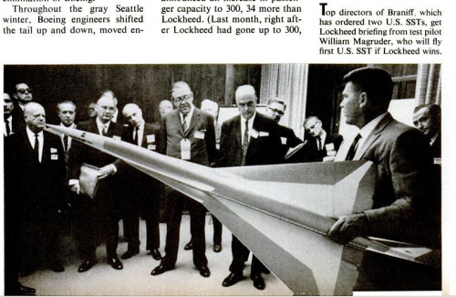
The Lockheed L-2000 was Lockheed's entry in a government-funded competition to build the United States' first supersonic transport (SST) in the 1960s. The L-2000 lost the contract to the Boeing 2707, but that competing design was ultimately canceled for political, environmental and economic reasons. In 1961, President John F. Kennedy committed the government to subsidizing 75% of the development of a commercial airliner to compete with the Anglo-French Concorde then under development. The director of the Federal Aviation Administration (FAA), Najeeb Halaby, elected to improve upon the Concorde's design rather than compete head-to-head with it. The SST, which might have represented a significant advance over the Concorde, was intended to carry 250 passengers (a large number at the time), fly at Mach 2.7-3.0, and have a range of 4,000 nmi (7,400 km). The program was launched on 5 June 1963, and the FAA estimated that by 1990 there would be a market for 500 SSTs. Boeing, Lockheed and North American officially responded. North American's design was soon rejected, but the Boeing and Lockheed designs were selected for further study.
Contents
1 Development 1.1 Early design studies
1.2 Later design studies
1.3 Design competition
2 Specifications (L-2000-7A)
3 See also
4 References
Development
Early design studies
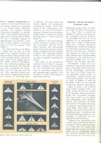
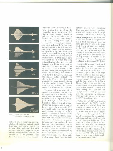
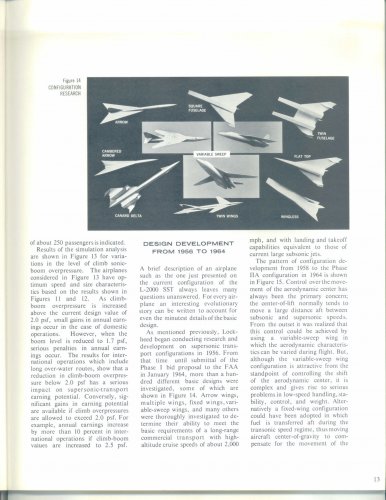
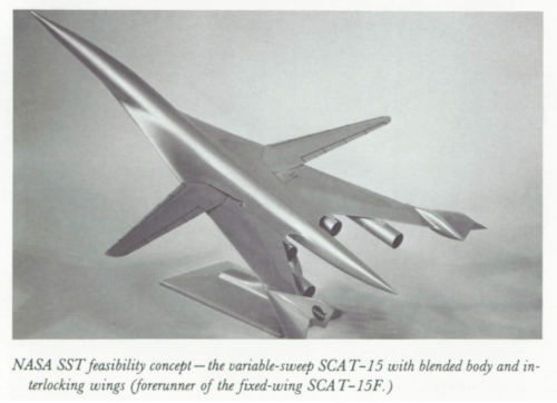
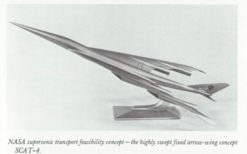
Like Boeing, Lockheed had done a number of "paper studies" on various SST designs, starting in 1958. Lockheed sought an airplane with cruise speeds of around 2,000 mph (3,219 km/h) with takeoff and landing speeds that compared to large subsonic jets of the same era. They also desired a plane whose center of pressure could be managed throughout the entire speed range. Lockheed knew a variable geometry, swing-wing design could accomplish this goal, but felt it was too heavy; however, they preferred a fixed-wing solution. In a worst-case scenario, they were willing to design a fixed-wing aircraft using fuel for ballast. Early designs followed Lockheed's tapered straight wing much like the type used on the F-104 Starfighter, with a delta-shaped canard for aerodynamic trim. The problem was that in wind-tunnel tests the shift in the airplane's C/L was substantial. A delta wing was substituted which alleviated a portion of the movement, but it was not deemed sufficient. By 1962, Lockheed arrived at a highly swept, bat-wing design featuring four-engine pods buried in the wings and a canard. The improvement was closer to their goal, but still not optimal. By 1963, they extended the leading edge of the wing forward a bit to eliminate the need for the canard, and re-shaped the wing into a double-delta shape with a mild twist and camber. This, along with careful shaping of the fuselage, was able to control the shift in the center of pressure caused by the highly-swept forward part of the wing developing lift supersonically. The engines were shifted from being buried in the wings to individual pods slung below the wings.
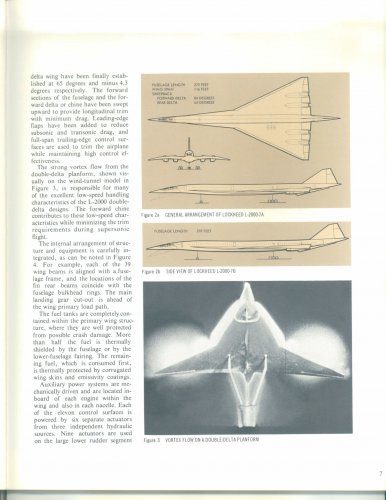
Later design studies
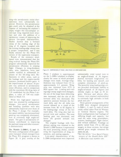
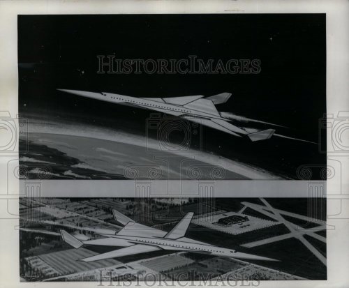
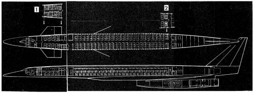
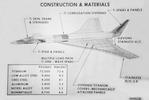
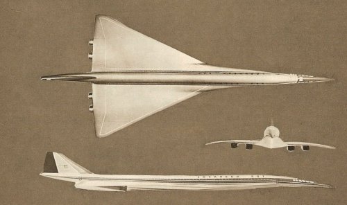
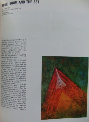
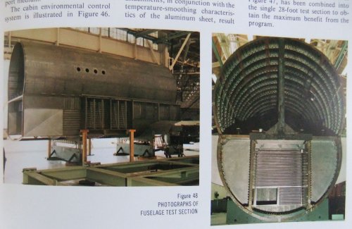
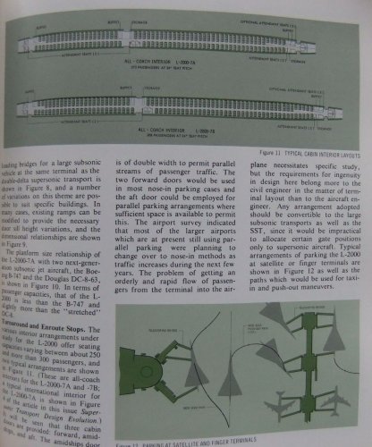
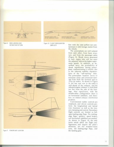
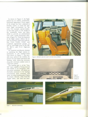
The new design was designated L-2000-1 and was 223 ft (70 m) long with a narrow-body 132 in (335.2 cm) wide fuselage to meet aerodynamic requirements, allowing for passenger seating of five abreast seating in coach and a four-abreast arrangement in first-class seating. A typical mixed-class seating layout would equal around 170 passengers, with high-density layouts exceeding 200 passengers. The L-2000-1 featured a long, pointed nose that was almost flat on top and curved on the bottom, which allowed for improved supersonic performance, and could be drooped for takeoff and landing to provide adequate visibility. The wing design featured a sharp forward inboard sweep of 80°, with the remaining part of the wing's leading edge swept back 60°, with an overall area of 8,370 ft² (778 m²). The high sweep angles produced powerful vortices on the leading edge which increased lift at moderate to high angles of attack, yet still retained stable airflow over the control surfaces during a stall. These vortices also provided good directional control as well, which was somewhat deficient with the nose drooped at low speeds. The wing, while only 3% thick, provided substantial lift due to its large area, which, aided by vortex lift, allowed takeoff and landing speeds comparable to a Boeing 707. Additionally, a delta wing is a naturally rigid structure which requires little stiffening. The plane's undercarriage was a traditional tricycle type with a twin-wheeled nose gear. Each of the two six-wheeled main gear utilized the same tires used on the Douglas DC-8, but which were filled with nitrogen and to lower pressures. To provide an optimum entry date into service, Lockheed decided to use a beefed-up turbofan derivative of the Pratt & Whitney J58. The J58 had already successfully proven itself as a high-thrust, high-performance jet engine on the top-secret Lockheed A-12 (and subsequently on the Lockheed SR-71 Blackbird.) Due to its being a turbofan, it was deemed to be quieter than a typical turbojet at low altitude and low speed, required no afterburner for takeoff, and allowed reduced power settings. The engines were placed in cylindrical pods with a wedge-shaped splitter, and a squarish intake providing the inlet system for the aircraft. The inlet was designed with the goal of requiring no moving parts, and was naturally stable. To reduce the noise from sonic booms, rather than penetrate the sound barrier at a more ideal 30,000 ft (9,144 m), they intended to penetrate it at 42,000 ft (12,802 m) instead. It would not be possible on hot days, but on normal days this would be achievable. Acceleration would continue through the sound barrier to Mach 1.15, at which point sonic booms would be audible on the ground. The plane would climb precisely to minimize sonic boom levels. After an initial level-off at around 71,500 ft (21,793 m), the plane would cruise climb upwards, ultimately reaching 76,500 ft (23,317 m). Descents would also be performed in a precise way to reduce sonic boom levels until subsonic speeds were reached. By 1964, the US Government issued new requirements regarding the SST Program which required Lockheed to modify their design, by now called the L-2000-2. The new design had numerous modifications to the wing; one change was rounding the front of the forward delta in order to eliminate the pitch-up tendency. To increase high-speed aerodynamic efficiency, the wing's thickness was reduced to 2.3%, the leading edges were made sharper, the sweep angles were changed from 80/60° to 85/62°, and substantial twist and camber were added to the forward delta; much of the rear delta was twisted upwards to allow the elevons to remain flush at Mach 3.0. In addition, wing/body fairings were added on the underside of the fuselage where the wings are located, allowing a more normally-shaped nose to be used. To retain low-speed performance, the rear delta was enlarged considerably; to increase the payload, the trailing edge featured a forward sweep of 10°. The new nose reduced the overall length to 214 ft (65.2 m) while retaining virtually the same internal dimensions. Wingspan was identical as before, and despite the thinner wing, the increased wing area of 9,026 ft² (838.5 m²) allowed the same takeoff performance. The airplane's overall lift-to-drag ratio increased from 7.25 to 7.94. During the course of the L-2000-2's development, the engine previously selected by Lockheed was no longer deemed acceptable. During the time frame between the L-2000-1 and L-2000-2, Pratt and Whitney designed a new afterburning turbofan called the JTF-17A, which produced greater amounts of thrust. General Electric developed the GE-4 which was an afterburning turbojet with variable guide-vanes, which was actually the less powerful of the two at sea level, but produced more power at high altitudes. Both engines required some degree of afterburner during cruise. Lockheed's design favored the JTF-17A over the GE-4, but there was the risk that GE would win the engine competition and Lockheed would win the SST contract, so they developed new engine pods that could accommodate either engine. Aerodynamic modifications allowed a shorter engine pod to be used and which utilized a new inlet design. This inlet featured minimal external cowl angles and was precisely contoured to allow a high-pressure recovery using no moving parts, and allowed maximum performance with either engine option. To allow additional airflow for noise-reduction, or to aid afterburner performance, a set of suck-in doors was added to the rear portion of the pod. To provide mid-air braking capability for rapid deceleration and rapid descents, and to assist ground braking, part of the nozzle could be employed as a thrust reverser at speeds below Mach 1.2. The pods were also repositioned on the new wing to better shield them from abrupt changes in airflow. The additional thrust from the new engines allowed supersonic penetration to be delayed until up to 45,000 ft (13,716 km) under virtually all conditions. Since at this point the possibility of supersonic overland flight was still considered to be an option, Lockheed also considered larger, shorter-ranged versions of the L-2000-2B. All designs weighed exactly the same, with a new tail design, changes to the fuselage length, extensions to the forward delta, increased capacity, and variations in fuel capacity. The largest version featured capacity for 250 domestic passengers, while the medium version featured transatlantic capability with 220 passengers. Despite the fuselage length changes, there was no appreciable increase in the risk of the aircraft pitching upwards too far (over-rotation) on takeoff.
Design competition
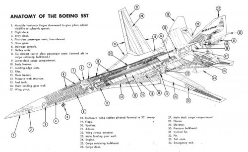
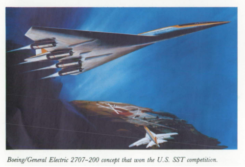
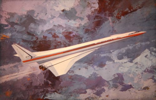
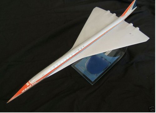
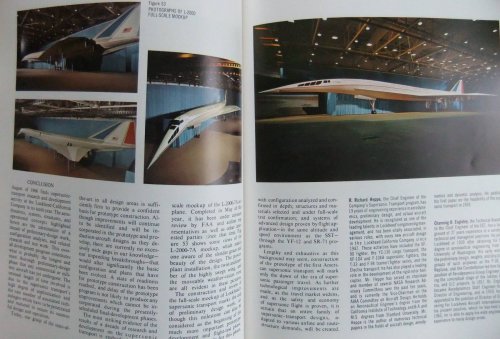
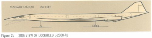
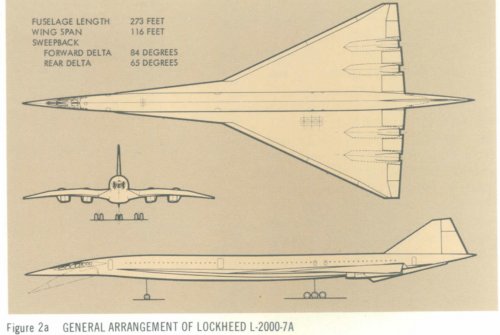
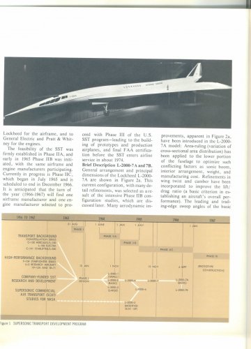
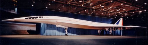
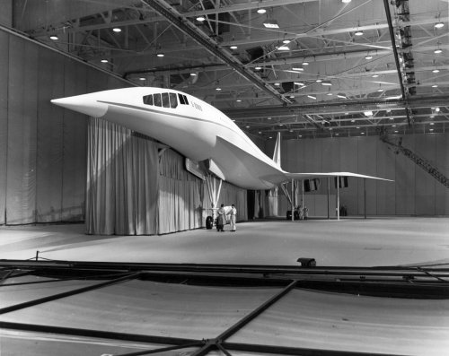
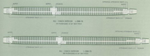
By 1966, the design took on its final form as the L-2000-7A and L-2000-7B. The L-2000-7A featured a re-designed wing and fuselage lengthened to 273 ft (83 m). The longer fuselage allows for a mixed-class seating of 230 passengers. The new wing featured a proportionately larger forward delta, with greater refinement to the wing's twist and curvature. Despite having the same wingspan, the wing-area was increased to 9,424 ft² (875 m²), with a slightly reduced 84° sweepback, and an increased 65° main delta wing, with reduced forward sweep along the trailing edge. Unlike previous versions, this aircraft featured a leading-edge flap to increase lift at low speeds, and to allow a slight down-elevon deflection. The fuselage, as a result of greater length, changes to the wing design, and attempts to further reduce drag, featured a slight vertical thinning in the fuselage where the wings were, a more prominent wing/body "belly" to carry fuel and cargo, a longer nose, and a refined tail. Since the airplane was not as directionally stable as before, the plane featured a ventral fin, located on the underside of the trailing fuselage. The L-2000-7B was extended to 293 ft (89 m), utilizing a lengthened cabin and a more pronounced upward-curving tail to reduce the chance of the tail striking the runway during over-rotation. Both designs had the same maximum weight of 590,000 lb (267,600 kg), and the aerodynamic lift-to-drag ratio was increased to 8:1. Full-scale mock-ups of the Boeing 2707-200 and L-2000-7 designs were presented to the FAA, and on December 31, 1966 the Boeing design was selected. The Lockheed design was judged simpler to produce and less risky, but its performance during takeoff and at high speed was slightly lower. Because of the JTF-17A, the L-2000-7 was also predicted to be louder as well. The Boeing design was considered more advanced, representing a greater lead over the Concorde and thus more fitting to the original design mandate. Ironically, Boeing eventually changed its advanced variable-geometry wing design to a simpler delta-wing similar to Lockheed's design, but with a tail. If Lockheed had built its simpler design, it might have flown by 1971. With technical problems, delays, cost overruns, and environmental and economic questions, the Boeing SST was ultimately canceled on 20 May 1971 after the US Congress stopped federal funding for the SST program on 24 March 1971.
Specifications (L-2000-7A)
General characteristics
Capacity: 273 passengers
Length: 273 ft 2 in (83.26 m)
Wingspan: 116 ft (35.36 m)
Height: ()
Wing area: 9,424 ft² (875 m²)
Empty weight: 238,000 lb (107,900 kg)
Max takeoff weight: 590,000 lb (276,600 kg)
Powerplant: 4× GE4/J5M or Pratt & Whitney JTF17A-21L
Performance
Cruise speed: Mach 3.0
Range: 4,000 nmi (7,400 km)
Service ceiling: 76,500 ft (23,317 km)
See also
Comparable aircraft
Boeing 2707
Concorde
Tupolev Tu-144
Related lists
List of Lockheed aircraft
References
Boyne, Walter J, Beyond the Horizons: The Lockheed Story. New York: St. Martin's Press, 1998. ISBN 0-31219-237-1.
Francillon, René J, Lockheed Aircraft Since 1913. Annapolis, Maryland: Naval Institute Press, 1987. ISBN 0-87021-897-2.
- See more at:
http://factgrabber.com/index.php?q=...qYa5xplkiWbJJ5EHwea5JxkG#sthash.MS9wx4ou.dpuf

") B)
B)