YF-23 Slope Soarer

Yak

ACCESS: Restricted
Joined
6 May 2011
Messages
20
Reaction score
0
I'm in the middle of modelling a YF-23 for construction in EPP foam for RC slope soaring duties.

Is anyone interested in such a build? This forum seems to be mainly for static modellers.

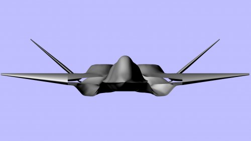
Happy to write a build log here. Would appreciate some input on my CAD design / fuselage shape etc.


Regards
Marty
 
OK then.

Step one. Head over to Up Ship and grab the images that Scott has which include a bunch of fuselage cross sections.

http://up-ship.com/drawndoc/drawndocair.htm

The attached thumbnail images are from the site and give you an idea. All those lovely cross sections!

adwg47ad2.jpg


I'm not affiliated with this site in any way. Seven bucks seemed quite reasonable.
 
Hi,

I'll certainly be watching with interest. Will you be stretching the span a little and what wing section are you proposing?

Best of luck!

S
 
Not sure on the span. Was thinking some sort of standard slope section like an MH32.

This is one weird wing for a glider. Root chord is longer than wing panel span.

I have a great slope site nearby that generates very good lift in any south easterly over 10 knots. The site is at Dobroyd Oval and takes its breeze straight through Sydney heads. Spectacular view as well as excellent lift. Landing out can be an issue as it is steep and bushy though.

But anyway, this, coupled with the shape of the fuselage lead me t thinking that I might try a scale wing first. That big wide fuselage should catch a whole heap of lift to help that of the wings.

Current plan is to have the wings detachable so I could always build a wider set as well.

I've cut foam now for the first few fuselage sections. Will post photos soon.

first bird will be EPS (polystyrene) as it is cheap and will serve as a test bed for CogG, setup etc.
 
Nothing wrong with MH32 and I think you'll be glad you opted for the plug-in wings.

As regards C/G location, a balsa 'chuckie' can certainly help. anything that makes that first few moments of flight less fraught is, in my eyes, a good thing.

Will you be skinning the foam in glass or going with a taped finish?
 
Actually thinking of adding a little more development risk to the project and using low temperature laminating film.

Have mainly used spray glue and tape for slope birds in the past but these were quite primitive things for combat.

Havn't glassed anything before. Don't know if I want to go to the hassle or learning that right now.
 
By the way, here is a screenshot to give a little idea of where I am up to with the CAD modelling.
 

Attachments

  • cad.png
    cad.png
    216.9 KB · Views: 841
Design help needed

OK, hit a tricky bit.

Any suggestions how to design the pivot that joins the all flying tailplanes to the fuselage?

Here is a CAD drawing of my initial idea. The cross member will have a hole drilled for the tailplane spar to go through. A control horn on the spar will link to a servo.

Better ideas anyone?
 

Attachments

  • cad2.png
    cad2.png
    162.2 KB · Views: 760
Exceptions

Well, I've had to bow to the requirements of flying a model glider and change the airfoil for the wing. Attached is a shot from the from showing the new fatter wing.

Looks like I get a bit of dihedral just from keeping the tip foil in line with the top of the root foil.

I'm using an MH32. In this shot at full thickness. What do you all think?
 

Attachments

  • F23 Front Render.jpg
    F23 Front Render.jpg
    56.4 KB · Views: 634
Well, from the CAD renderings, I think it looks great. In the interest of getting it to work on the slope, consider pushing the span as far as you can (and re-sizing the tails accordingly).

Re the all-moving V-tail, doing those neatly is always a tricky one. See the Muller Elita F3F model as an example. Jaro Muller's work is always top-notch but even his A/M V-tail was... shall we say; less than his finest hour?

Ultimately, there will be trade-offs to be made between scale fidelity and PSS usability. Where you put these depends on your priorities. To that end, if it makes the build easier and if it means you can actually fly it, go with a fixed tail and control surface. PSS models can be seen to be excercises in pragmatism.

Keep up the good work :)
 
Here is the rudder mechanism so far. Steering arms are in my recent order from HobbyKing. :)

I have the bulkheads and cross members cut out already on a mate's CNC 3 axis router. Am now working out hwo to run some snake forward and where to mount the servos.

I've had a look at bigger spans and will possibly go that way as well. Will try a scale wing (apart from thickness) first.
 

Attachments

  • Rudder4.png
    Rudder4.png
    97.9 KB · Views: 533
So, I'm thinking about CofG for this model and have noted that while there is no CofG shown there is marked on my images a spot for the roll, pitch and yaw gyroscopes.

Would it make sense from a design / functionality perspecive to have placed these at or near the CofG? The spot where they are looks like about where I expected it to be.

Any thoughts?
 

Similar threads

Back
Top Bottom