Stealth Wings and C of G

Yak

ACCESS: Restricted
Joined
6 May 2011
Messages
20
Reaction score
0
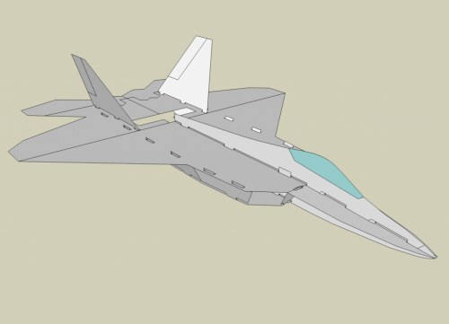
I'm building three models at the moment for RC slope soaring. They are the F35, F22 and X23. As mentioned previously on the list I'm trying out cutting the fuselages in 50mm EPP foam slices on a computer driven hot wire.

I have a couple of test cuts of the F35 fuselage done already (although I am not sold on my CAD work accuracy for this model) and am working up the F22 and X23 in CAD.

My question to the list (for both modellers and real life engineers) is this:

Where the hell is the centre of gravity calculated for these weird wing shapes? Does anyone have an idea? Do you average the chord and put it at a third of that? Or is there some sort of (more accurate) way of working this out?


Regards
Marty
 
According to my aircraft design book, the center of gravity of a wing can be approximated as being 40% of the mean aerodynamic chord.
 
You could use software like XFLR5 (free) but AFAIR it's not good if there's a lot of sweep.
 
Get hold of a copy of 'Model Aircraft Aerodynamics', by Martin Simons.

http://www.amazon.co.uk/Model-Aircraft-Aerodynamics-Martin-Simons/dp/1854861905/ref=sr_1_1?s=books&ie=UTF8&qid=1306575088&sr=1-1

Everything you need is in there....


cheers,
Robin.
 
Hi Guys,

Currently I'm working on same problem like determining the centroid of an airplane, i.e. Piper PA-28 structure in AutoCAD.

If you have made it in AutoCAD as solid model, i.e. Wing structure, you can use the command Mass Properties to determine not just its centroid or CG but its moment of inertia and other mass properties.
 
Wide bodied aircraft like the F-22 and F-35 generate large amounts of lift from their fuselages and calculating a CG based only on their wings leaves out a lot of area that generates significant lift.

A simple empirical method to come up with a CG is to build a "Shockflyer" style (full horizontal and vertical profiles) glider of Depron (similar to meat tray foamed plastic sheet) or sheet balsa about a foot in length. Balance the horizontal profile on a straight edge and you will get the center of pressure (CP) and the CG will need to be somewhere ahead of the CP for stable airplane. Assemble the vertical profile to the horizontal profile and test glide and add weight to the nose until you get a good glide. Mark the CG on the glider and transfer it to to the corresponding location on your airplane as a beginning CG and test glide over high grass until happy. With neutral elevator, pitch up will indicate tail heavy, pitch down indicates nose heavy, and a smooth glide indicates you have found a good CG.

The picture below illustrates the construction of a "Shockflyer" style F-22 electric powered flying model and you can find the plans and article for it in the RC Groups Forum here:
http://www.rcgroups.com/forums/showthread.php?t=723890 For your CG glide test model, it would not be necessary to build the engine box part of the fuselage.

Richard
 

Attachments

  • F-22 Profile Model.png
    F-22 Profile Model.png
    294.6 KB · Views: 495
Thanks for the shockflyer idea Richard.

I've gotten some CAD files worked out and am going to cut a EPS (polystyrene) foam chuck glider first. (similar idea I guess). The EPS is nice in that it is relatively cheap.

EPP (polypropylene will follow once I know where the CG goes and I'll cut compartments for the radio gear and batteries so that I get the CG right.
 

Similar threads

Back
Top Bottom