Wasserfall antiaircraft rocket

Well, from guidance law perspective it made little difference if target was moving in air or was standing on ground. Aerial target is even simpler in fact due to being point target at low contrast background. Anyways, I might quess that this was simple lead sulfide based AM-modulated seeker, like all those zero and first gen seekers. Still interesting to know if they used some unusual solutions in it.

In theory - yes. On practice, the engineering solutions are quite complex, because both targets & missile are moving in 3D with considerable speed, both linear & angular.
 
Anyways, I might quess that this was simple lead sulfide based AM-modulated seeker, like all those zero and first gen seekers. Still interesting to know if they used some unusual solutions in it.

Well, Wiki quoted the Benecke "History of German guided missile development" (unfortunately I did not have this work):

AEG and Kepka of Vienna used systems with two movable plates that continually scanned horizontally or vertically, and determined the location of the target by timing when the image disappeared (AEG) or reappeared (Kepka). The Kepka Madrid system had an instantaneous field of view (IFOV) of about 1.8 degrees and scanned a full 20 degree pattern. Combined with the movement of the entire seeker within the missile, it could track at angles as great as 100 degrees.

So it seems to be the rather primitive device, in which seeker rotates to provide scanning with some "blind spot" directly forward. If the target appeared in sight, then the seeker relay would be closed, and the exact moment in seeker scanning cycle, during which target was observed, would determine the autopilot response. And if the target is directly ahead, then it would disappear from seeker field of view completely & missile would flight straight forward.

The obvious problem with that kind of device is that it have no ability to discriminate between "target directly forward" and "no target". So if target was lost, the missile would make no attempt to reacquire, because (from its point of view) the trget is still directly forward. Also, when fired against bomber formation, seeker would probably be very confused by multiple signatures, and missile would zig-zag between bombers, not hitting anything.
 
more complex task, because it would need to hit a target in 3D space
I think, guiding a missile at an aerial target is still guiding in 2D space, only X/Y coordinates have to be controlled.

So it seems to be the rather primitive device, in which seeker rotates to provide scanning with some "blind spot" directly forward.
According to my notes, the Madrid was equipped with a 28 cm parabolic mirror, pneumatically moved, an Elac IR detector cooled with LOX, and 5 tubes. FOV was 18 degrees, switching to 1.5 degree after locking on a target, range probably 3000 m.
 
Last edited:
I am interested specifically in IR seeker.
unfortunatey there are no books known which contain actual mechanisms and circuits for ir seekers as only few internet website explain the theory but how actually it is done is still a mystery as engineers still hide it.But building ir seekers sholudn't be a big deal since if you can built a "sun tracker(ir diode only)" then practically you have a seeker.
 
The significant issue for an IR system at the time would be signal to noise. The electrical output from the cell is tiny, the piston engine exhaust was rapidly diluted in cool air and the 40’s vintage thermionic values were inherently electrically noisy. So one way to fix this is improve the signal by increasing the delta T hence the use of LOX . This fundamental problem was only really practically fixed when the transistor (which works well at low signal levels) came about and jets provided a much hotter heat source.

Ten years after the German work when the IR homing Firestreaks were tested against radio control piston engine targets (Fairy Firefly’s) they had to install a kerosene fuelled blow lamp in a pod to provide a workable heat source.
 
Last edited:
I think, guiding a missile at an aerial target is still guiding in 2D space, only X/Y coordinates have to be controlled.

Only if you use the straightforward approach, i.e. when the missile is aiming directly at the plane.

According to my notes, the Madrid was equipped with a 28 cm parabolic mirror, pneumatically moved, an Elac IR detector cooled with LOX, and 5 tubes. FOV was 18 degrees, switching to 1.5 degree after locking on a target, range probably 3000 m.

Thank you for the data!

unfortunatey there are no books known which contain actual mechanisms and circuits for ir seekers as only few internet website explain the theory but how actually it is done is still a mystery as engineers still hide it.But building ir seekers sholudn't be a big deal since if you can built a "sun tracker(ir diode only)" then practically you have a seeker.

Well, the old-type IR seekers are well-known. You could find the complete description of Ke-Go IR seeker here:


Of course, it was quite primitive device, but workable, and it get the whole theory.
 
Only if you use the straightforward approach, i.e. when the missile is aiming directly at the plane.
Egh... No? Missile with IR seeker (and in fact many other types of guidance) don't know range to target and not flying straight at it, but into predicted interception point trough zeroing angular velocity.
 
Egh... No? Missile with IR seeker (and in fact many other types of guidance) don't know range to target and not flying straight at it, but into predicted interception point trough zeroing angular velocity.

Such primitive seeker as mentioned above - that could only detect the "appearance/disappearance" of the target have no means to calculate the predicted interception point. Modern one - yes, could use constant bearing. But those WW2 units could, at best, point the missile straight on target.
 
So it seems to be the rather primitive device, in which seeker rotates to provide scanning with some "blind spot" directly forward.
As I understand, the Madrid had no blind spot, it used lineal scanning of the whole FOV with a pair of perpendicularly moving masks, with target coordinates established by timepoints, at which the masks were revealing the target.
 
Such primitive seeker as mentioned above - that could only detect the "appearance/disappearance" of the target have no means to calculate the predicted interception point. Modern one - yes, could use constant bearing. But those WW2 units could, at best, point the missile straight on target.
If by "modern ones" you mean oldest ones with simple AM seekers - then I can agree.
 
For me.. the only problem for Wasserfall is that there just not enough time for it to properly developed.
 
By the way - what was so wrongly designed in the Wasserfall?

As far as I knew, when Soviet engineers designed R-101 missile (reverse-engineered Wasserfall), they were forced to eventually redesign the whole engine, because German one was just impossible to made reliable and re-work the feeding system, because German one was inefficient. The command guidance system never worked as intended, and our engineers were of general opinion that it is pointless even to try to make it right, because it was basically a modified variant of Kehl-Strasbourg RC system, essentially a 1930s technology.

Eventually, the situation came to the point when there were no two exactly similar examples of R-101, because each attempt to perfect the system caused more and more rebuilds. In 1951, the R-101 project was cancelled because no one could actually be sure that this pile of German junk could be made workable at all.
 
I am looking for references confirming a couple of details relating to the German Wasserfall Surface To Air missile.

The first is the name of the missile tracker in the proposed radar guided variant. Some articles say this was called Rheingold. Some of the earlier aparently high quality technical sources call the overall guidance system Elsas and identify the target tracker as Mannheim, but give no codename to the missile tracker. Does anyone have a reliable reference to confirm the missile tracker was ever called Rheingold ?

My other query is whether Wasserfall dropped its graphite exhaust gas vectoring fins once it had enough speed to depend on the large control surfaces on the external fins. A few articles say it did this to reduce weight, but the footage of test launches on YouTube doesnt confirm this. Again, anyone know of reliable sources that confirm this detail ?

Huge Thanks

Nick
No, there is no tracking system for that missile called Rheingold. There is a single drawing, the source is sketchy, that refers to that radar.

As for the graphite veins, those are for stability and roll control on the missile while the trailing control surfaces are to turn the missile towards its target. The missile has to know which way is "up" to be guided in flight. GE retained them on the Hermes series for the same purpose post war.

With the V-2, guidance was simpler because it flew a ballistic course, and the graphite veins could handle that in 2-axis motion. With Wasserfall, during the first 6 seconds of flight, the graphite veins control the roll and pitch of the missile using a system called Ruse that is a telemetry radio link that sends commands to the missile. Once it gains enough range and altitude the guidance system--optical or radar--takes over and the operator using the MCLOS link with either Keil Straßburg or Kogge Brigg system guides it. Either Würtzburg or Mannheim radars (Reise usually) were to be used for tracking both the missile and target and these fed data to an Einlink electro-mechanical computer that gave an output to a CRT scope showing the position of the missile in relation to the target that was centered in the display on crosshairs.

With the optical systems the data was fed to a Marsai table with special drums being used specifically for the missile. Guidance was done by the operator watching the plot on the table as it would be done for guns using the same system.

Because of the long wavelengths of the radars available to the Germans, the sets would have been several kilometers from the launch site. That made Ruse necessary.
 
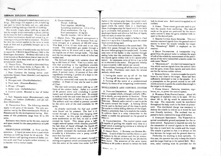
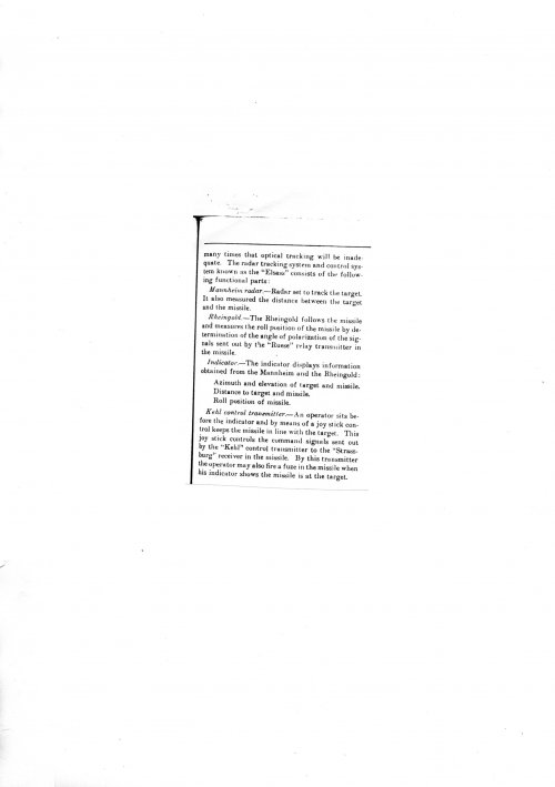
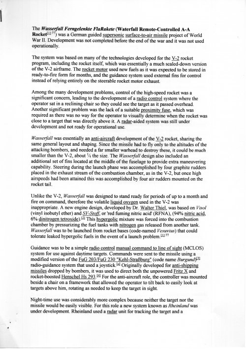
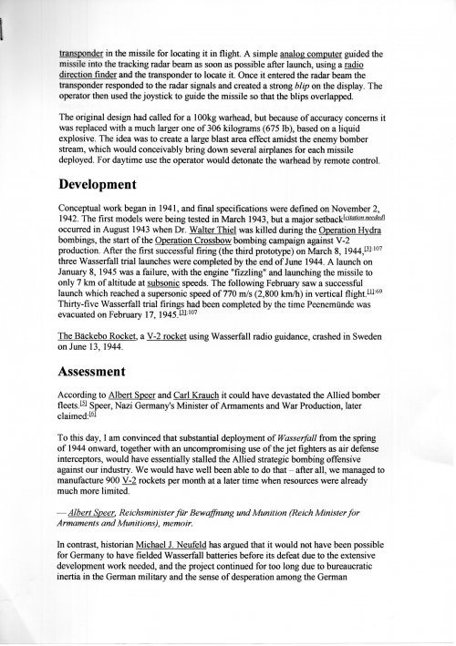
This is the information I have about Wasserfall, I hope it can help.


EMW Wasserfall


In September 1942, Elektromechanische Werke-Peenemünde (EMW) started the development of a high-altitude, anti-aircraft, supersonic missile (based in the V-2) under the codename EMW C-2 8/45.

About twenty-five wind tunnel models, with six different aerodynamic configurations, were tested at speeds up to Mach 3.0.

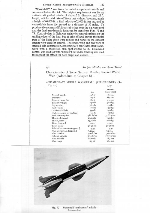
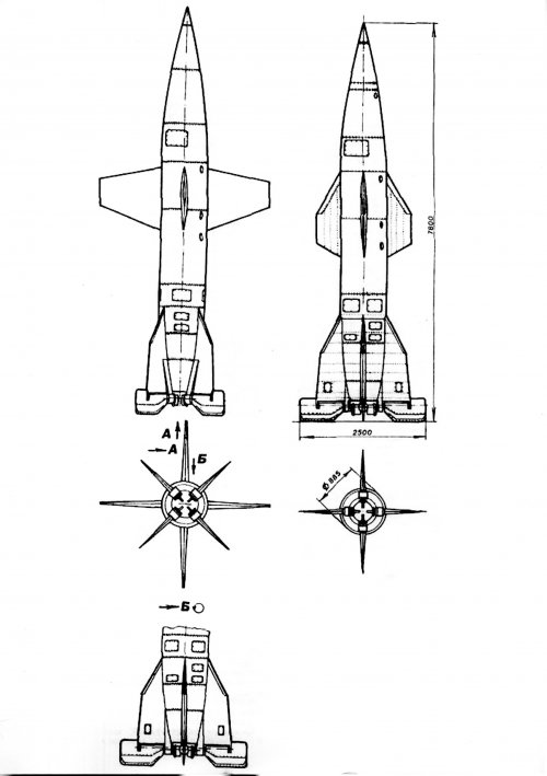
The original requirement was for an anti-aircraft guided rocket of about 900-mm of diameter and 8,000-mm length, which could take-off without boosters, attain 18,000 m of altitude and 800 m/sec speed.

In February 1943 the project was accepted by the OKL under the codename Wasserfall.

Two prototypes of the W-1 Series were built at the Peenemünde facilities early in 1944.

The first launch test was performed on February 28,1944 at Greifswalder Oie. The prototype was flown at subsonic speed reaching only 7,000 meters altitude, but the second missile reached 2,272 km/h on March 8,1944.

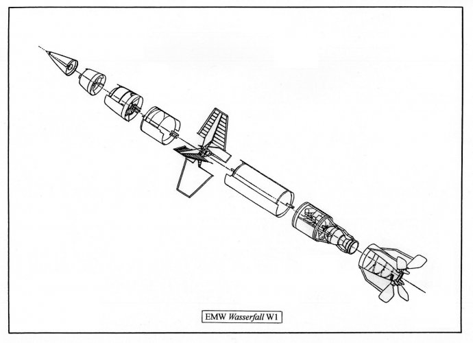
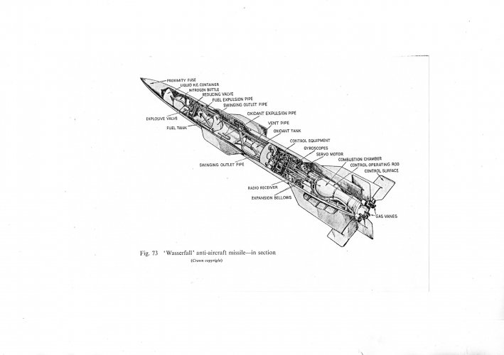
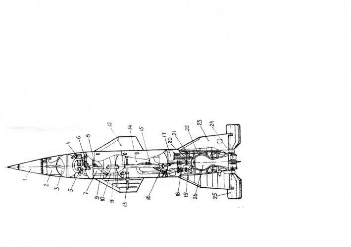
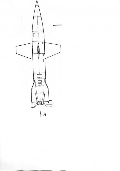
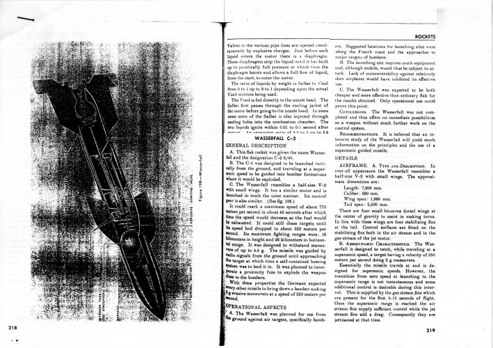
W-1 was built from mild steel, the body, wings and fins were of stressed skin construction consisting of a steel framework with a sheet-steel skin spot welded to it.

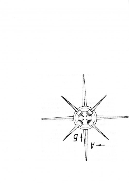
It was fitted with four biconvex wings to assist in making high-altitude pursuit curves at high speed and 4.4 g.

The W-1 was designed to intercept lone Spitfire and Mosquito reconnaissance aircraft that proved very difficult to shoot down by conventional Luftwaffe fighters. To increase maneuverability at high altitude the wings were mounted offset by 45-degrees from the tail fins.

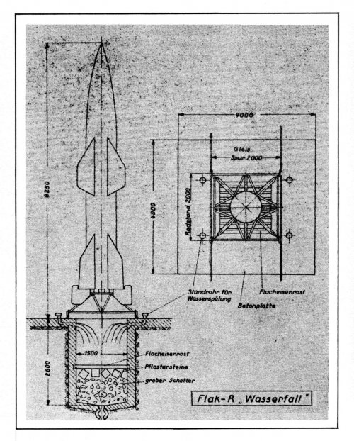
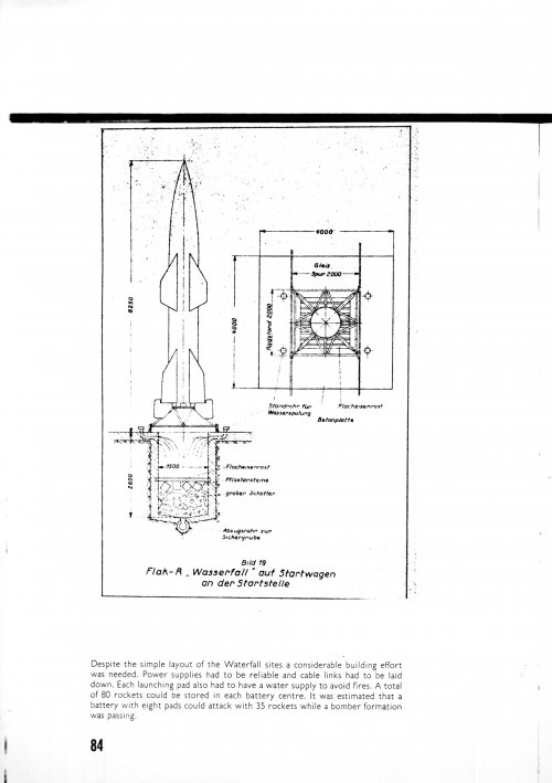
Wasserfall was launched at 22 m/sec in vertical position, like a V-2.

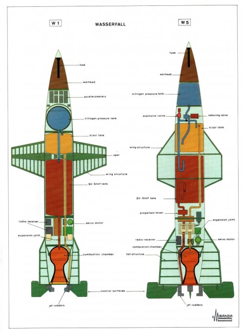
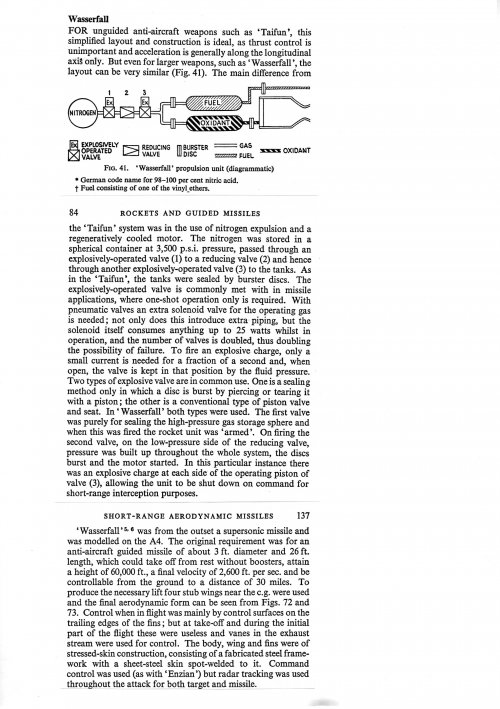
During take-off the missile was controlled by a three-axes gyro auto-pilot driving four detachable jet rudders mounted into the rocket nozzle. During the flight, control was achieved by means of four air rudders mounted in the tailfins. All the control rudders were operated by four Askania hydraulic servo motors.

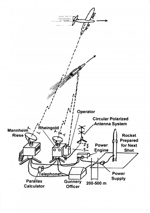
Radio-control commands were sent to the missile by means of the Burgund MCLOS system, a modified version of the Kehl/Strassburg control.

EMW 
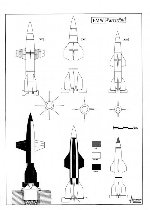
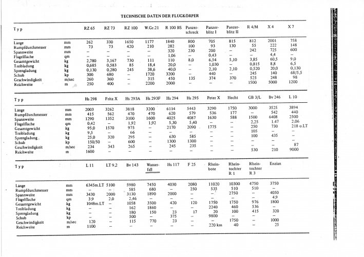
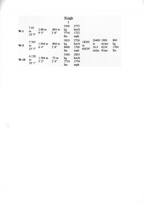
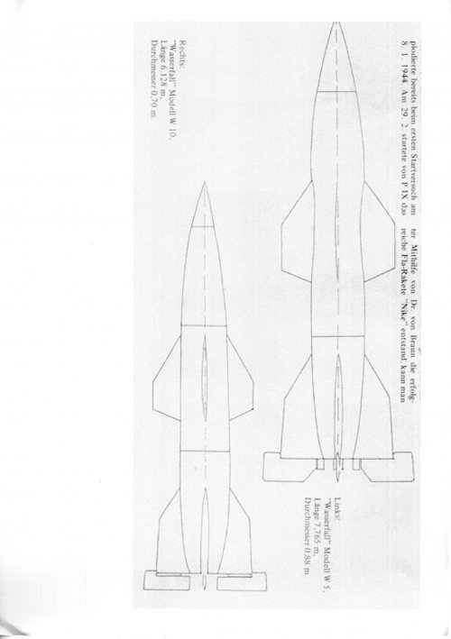
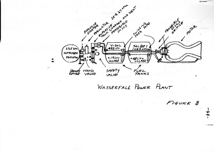
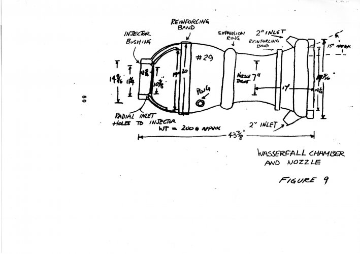
Wasserfall W-1 technical data

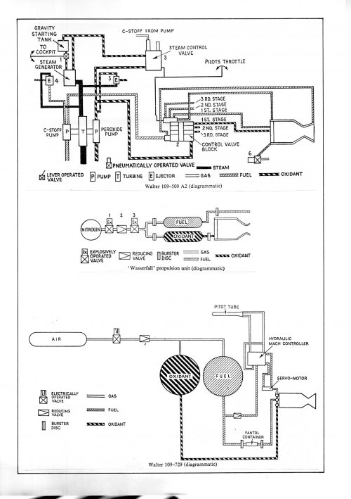
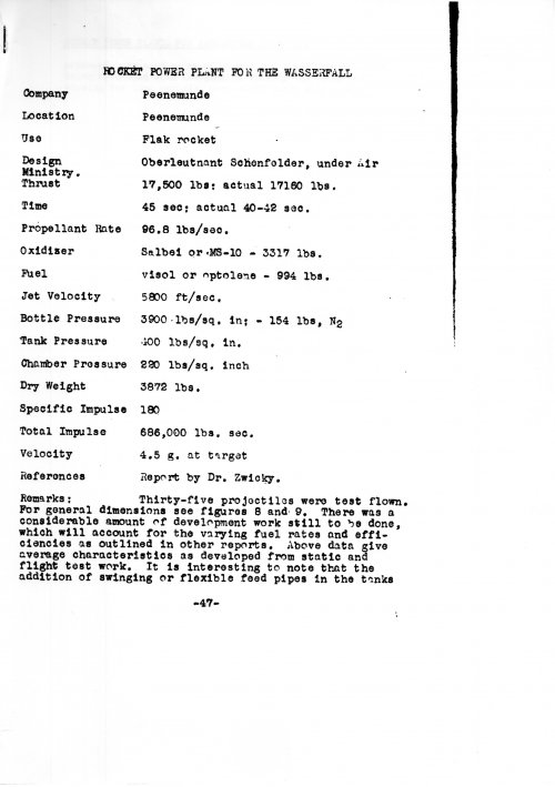
Wingspan: 2,880-mm, length: 7,450-mm, diameter: 864-mm, weight: 3,570 kg, speed: 2,772 km/h, service ceiling: 7,000 m, range: 12 to 18 km, warhead: 150 kg with 40 m lethal radius, power plant: one by-propellant rocket engine EMW, developed by Dr. Thiel and Oberleutnant Schönfelder, with 7,780 kg peak thrust and 45 seconds life, propellants: SV-Stoff + Visol + compressed nitrogen.


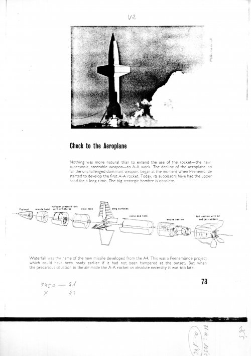
A second development was underway in April 1944.

The W-5 was designed as Pulkzerstörer weapon against U.S. bomber formations, it was slightly larger than the W-1 and its wings were smaller and sharply back.

The beam-control accuracy of Burgund decreased with extended range, in the production version it was expected to be able to use the most advanced Rheinland automatic control system and the IR terminal seeker Madrid.

Using Rheinland the missile would ride up the beam to the target. The new system did not require visual tracking and could also be used at night against British bombers.
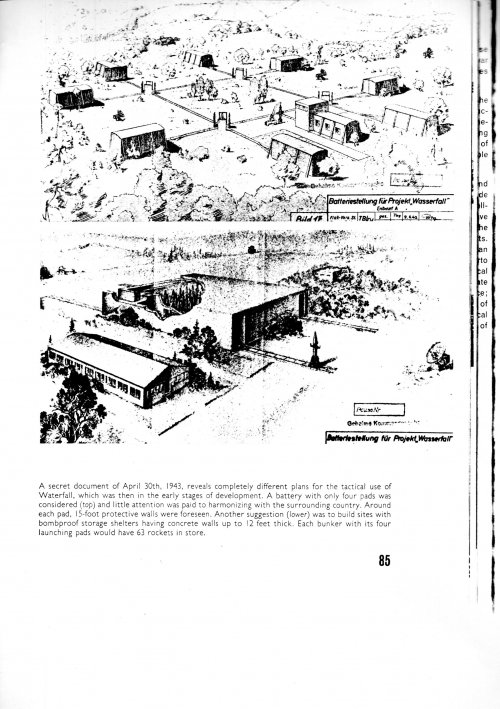
In early 1945 the Luftwaffe planned to deploy the Wasserfall at 2,000 Vesubius Flakbatteries with 35 launch pads each.

The production rate expected from November 1945 was 5,000 missiles per month, but only 35 prototypes were built and flight tested.
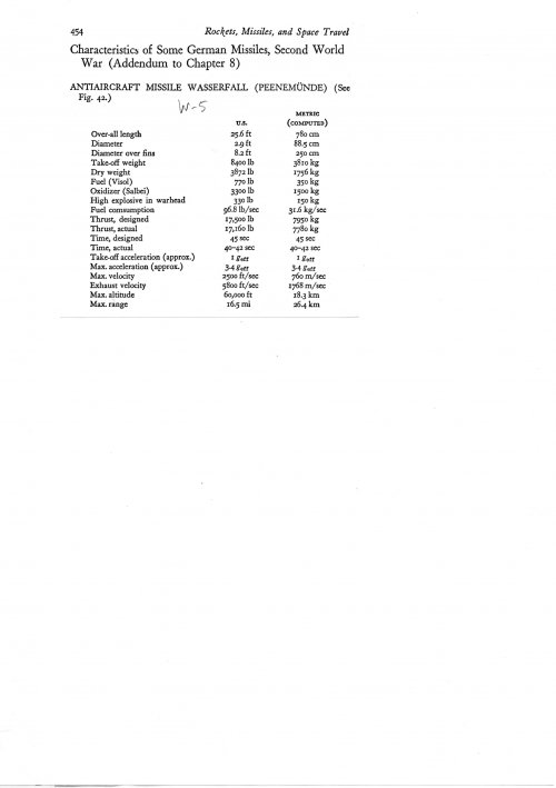
EMW Wasserfall W-5 technical data

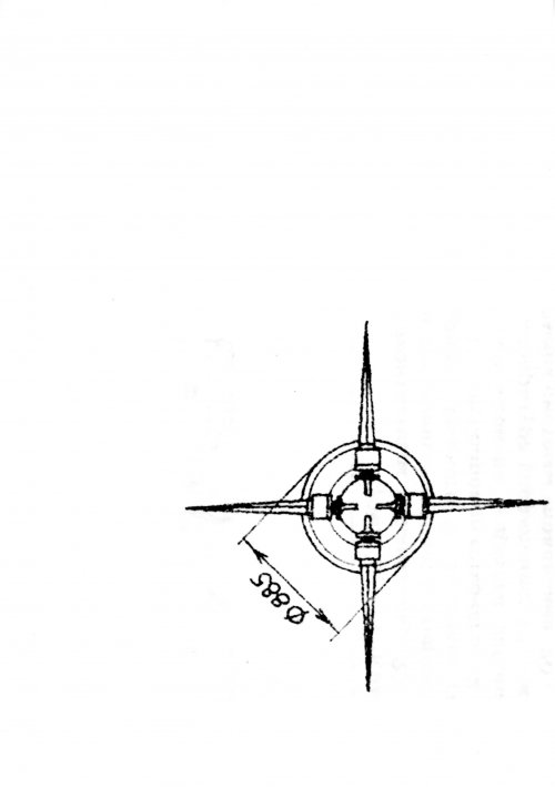
Wingspan: 1,980-mm, length: 7,765-mm, diameter: 885-mm, weight: 3,810 kg, speed: 2,736 km/h, service ceiling: 18,300 m, range: 26.4 km, warhead: 235 kg, power plant: one by-propellant rocket engine EMW, with 7,950 kg peak thrust and 45 seconds life, propellants: 770 kg of SV-Stoff + 1,500 kg of Visol + compressed nitrogen.

The W-10 was designed in January 1945 by Dipl. Ing. Roth as cheap 27 per cent scaled down W-5, using far less fuel. Roth estimated that it was not necessary to use much fuel to reach 18 km altitude when most enemy bombers routinely flew at altitudes of 7,000 to 8,000 meters. W-10 was also designed as Pulkzerstörer with one powerful warhead.

EMW Wasserfall W-10 technical data

Wingspan: 1,584-mm, length: 6,128-mm, diameter: 720-mm, weight: 3,500 kg, speed: 2,855 km/h, service ceiling: 8,000 m, range: 18 km, warhead: 305 kg of liquid explosive, power plant: one by-propellant rocket engine EMW, with 7,950 kg peak thrust and 45 seconds life, propellants: SV-Stoff + Tonka Optolin + compressed nitrogen.

Project cancelled on February 26, 1945.
 

Attachments

  • x.jpg
    x.jpg
    167.9 KB · Views: 52
  • xxx.jpg
    xxx.jpg
    836.8 KB · Views: 58
  • xx.jpg
    xx.jpg
    230.2 KB · Views: 64
  • xxxx.jpg
    xxxx.jpg
    301.9 KB · Views: 56
Post-2
 

Attachments

  • 065.jpg
    065.jpg
    785.5 KB · Views: 50
  • 066.jpg
    066.jpg
    714.6 KB · Views: 42
  • 067.jpg
    067.jpg
    115.3 KB · Views: 34
  • 068.jpg
    068.jpg
    724.6 KB · Views: 32
  • 069.jpg
    069.jpg
    521.9 KB · Views: 31
  • 070.jpg
    070.jpg
    332.6 KB · Views: 34
  • 071.jpg
    071.jpg
    757.9 KB · Views: 36
  • 072.jpg
    072.jpg
    492.3 KB · Views: 33
  • 073.jpg
    073.jpg
    765 KB · Views: 30
  • 074.jpg
    074.jpg
    150.7 KB · Views: 37
Post-3
 

Attachments

  • 075.jpg
    075.jpg
    663.1 KB · Views: 49
  • 076.jpg
    076.jpg
    331.7 KB · Views: 47
  • 077.jpg
    077.jpg
    368.9 KB · Views: 44
  • 078.jpg
    078.jpg
    272 KB · Views: 48
  • 079.jpg
    079.jpg
    362.5 KB · Views: 53
  • 081.jpg
    081.jpg
    527.8 KB · Views: 50
  • 083.jpg
    083.jpg
    808.2 KB · Views: 47
  • 084.jpg
    084.jpg
    222.8 KB · Views: 39
  • 085.jpg
    085.jpg
    795.5 KB · Views: 37
  • 086.jpg
    086.jpg
    264.6 KB · Views: 43
post-4
 

Attachments

  • 087.jpg
    087.jpg
    1.1 MB · Views: 43
  • 088.jpg
    088.jpg
    1.3 MB · Views: 43
  • 089.jpg
    089.jpg
    1.1 MB · Views: 41
  • 090.jpg
    090.jpg
    1.4 MB · Views: 46
  • 091.jpg
    091.jpg
    956.4 KB · Views: 46
  • 092.jpg
    092.jpg
    372.3 KB · Views: 43
  • 095.jpg
    095.jpg
    546.8 KB · Views: 45
  • 099.jpg
    099.jpg
    272.3 KB · Views: 41
  • 100.jpg
    100.jpg
    157.3 KB · Views: 38
  • 101.jpg
    101.jpg
    153.2 KB · Views: 35
Post-5
 

Attachments

  • 102.jpg
    102.jpg
    160.9 KB · Views: 42
  • 103.jpg
    103.jpg
    307.7 KB · Views: 50
  • 105.jpg
    105.jpg
    732.9 KB · Views: 48
  • 106.jpg
    106.jpg
    342.5 KB · Views: 45
  • 107.jpg
    107.jpg
    950.8 KB · Views: 39
  • 108.jpg
    108.jpg
    911 KB · Views: 37
  • 109.jpg
    109.jpg
    236.3 KB · Views: 43
  • 110.jpg
    110.jpg
    862.1 KB · Views: 51
  • 111.jpg
    111.jpg
    988.8 KB · Views: 50
  • 112.jpg
    112.jpg
    713.6 KB · Views: 39
Post-6
 

Attachments

  • 113.jpg
    113.jpg
    149.8 KB · Views: 32
  • 114.jpg
    114.jpg
    861.8 KB · Views: 27
  • 115.jpg
    115.jpg
    1.2 MB · Views: 30
  • 116.jpg
    116.jpg
    391.6 KB · Views: 32
  • 117.jpg
    117.jpg
    500.3 KB · Views: 38
  • 118.jpg
    118.jpg
    430.9 KB · Views: 34
  • 119.jpg
    119.jpg
    407.3 KB · Views: 30
  • 120.jpg
    120.jpg
    157 KB · Views: 31
  • 121.jpg
    121.jpg
    343.1 KB · Views: 35
  • 122.jpg
    122.jpg
    322.5 KB · Views: 33
Post-7
 

Attachments

  • 123.jpg
    123.jpg
    213.3 KB · Views: 36
  • 124.jpg
    124.jpg
    1.4 MB · Views: 31
  • 125.jpg
    125.jpg
    1.2 MB · Views: 28
  • 126.jpg
    126.jpg
    210.4 KB · Views: 29
  • 127.jpg
    127.jpg
    972.4 KB · Views: 29
  • 128.jpg
    128.jpg
    803.4 KB · Views: 27
  • 129.jpg
    129.jpg
    218 KB · Views: 26
  • 130.jpg
    130.jpg
    938.6 KB · Views: 27
  • 131.jpg
    131.jpg
    287.9 KB · Views: 25
  • 132.jpg
    132.jpg
    790 KB · Views: 29
Rheingold was an acoustic proximity fuze, as far as I know.
A manual guidance system for AA missiles was called Rheinland and had to use one or two Mannheim radars, depending on the variant.
I suspect at the time, the US technical teams doing the investigation in Germany, be it FIAT or some other one, simply got things mixed up on what was called what.
 
Chaps

Huge thanks for all your input. It’s very much appreciated. Especially Justo for the comprehensive set of scans.

I think T A Gardner summed it up well regarding confusion. One of the things that makes C-2 Wasserfall so interesting is that it’s so obscured by the fog of war that covered Europe in 1944/45. Same for the A9/A10. A combination of other things to think about, destroying secret documents to stop the allies getting them, allies pillaging the records for valuable technical data and then post war writers making things up hasn’t helped. But separating the facts from the fiction is all part of the fun :).
 
I’ve continued to dig on the question of whether the C2 Wasserfall jettisoned its thrust vector control vanes once its velocity was sufficient to depend on aerodynamic control.

Sources vary. A few say its was planned to improve efficiency but the vanes burned off anyway so wasn’t needed. A few others say the vanes burned unevenly, causing asymmetric thrust, making jettison critical.

Ive found a very good technical article on Wasserfall in a 1951 Interavia magazine by Rudolf Reichel. I think Reichel was at Peenemunde so can be regarded as a primary source ? His article stated that it was set up for vane jettison, each vane and backplate assembly being held in a slide rail by a squib operated bolt.

I have yet not found a wartime German language technical report that confirms this, so would say squib jettison on C2 is 80 percent but not certain.

I think a fair number of early missiles that followed the war also used graphite TVC vanes. Does anyone know if any of those had a scheme to jettison vanes once up to speed ?
 
Ive found a very good technical article on Wasserfall in a 1951 Interavia magazine by Rudolf Reichel. I think Reichel was at Peenemunde so can be regarded as a primary source ? His article stated that it was set up for vane jettison, each vane and backplate assembly being held in a slide rail by a squib operated bolt.
Here the complete paper:
 

Attachments

  • Interavia_1951_6_10 Wasserfall.pdf
    2.3 MB · Views: 50
Bundesarchiv Files

SOURCE: BUNDESARCHIV
SIGNATUR: RL 36/600
Batteriestellungen für Projekt "Wasserfall".- Entwürfe A bis C (Skizzen)
1.- three different Wasserfall batteries
[CLICK "DIGITALISAT ANZEIGEN" TO VIEW THE FILE]

Source: Bundesarchiv
Signatur: RL 3/67
Flakraketen.- Einsatz und Bodenorganisation - 1943
[CLICK "DIGITALISAT ANZEIGEN" TO VIEW THE FILE]
 
Wasserfall Variants

Bundesarchiv Files

[CLICK "DIGITALISAT ANZEIGEN" TO VIEW THE FILES]

Signatur: RH 8/1820
Dreikomponentenmessungen an einer aerodynamisch verbesserten Form der Flakrakete C2
https://invenio.bundesarchiv.de/invenio/direktlink/5fe32aef-1863-43ae-ac97-14f2d38f0f86/
[Three-component measurements on an aerodynamically improved C2 anti-aircraft rocket]

Signatut: RH 8/1816
Dreikomponentenmessungen an fünf verschiedenen Formen der Flakrakete C2
https://invenio.bundesarchiv.de/invenio/direktlink/9d63f872-1895-4996-8660-60bcf7fcfff5/
[Three-component measurements on five different forms of the C2 anti-aircraft rocket]

Signatur: RH 8/1928
Neue Projekte für fern-artilleristische Zwecke - 1944
https://invenio.bundesarchiv.de/invenio/direktlink/2961b7f4-0e41-42f0-a382-4f8367e39f78/
- modified Wasserfall surface - to - surface

Signatur: RH 8/1793
Wasserfall - Windkanaluntersuchungen

Signatur: RH 8/4133K
Comparison Wasserfall W10 - W5, February 1945

Signatur: RH 8/4082K
Projekt Wasserfallgleiter, 1944
Projekt Bemannung (Entwurf), 1:5, 1944
Flak-Rakete mit Starthilfe, 1944
Projekt Wasserfallgeschoss
Projekt Taifun II 1944
Projekt Bock (Vorentwurf) 1944
Projekt Modell PF, März 1945
https://invenio.bundesarchiv.de/invenio/direktlink/a143c440-1bdf-41ff-820d-090cf15d0711/
[No Digitalisat available]
 
Last edited:
ADA AIR DEFENSE ARTILLERY Magazine
March - April 1991
"Gulf War Weaponry Spawned in WWII"
by Wolf Prow
Page: 41 - 43
- Artwork: Wasserfall vs. Flying Fortress
 
unfortunatey there are no books known which contain actual mechanisms and circuits for ir seekers as only few internet website explain the theory but how actually it is done is still a mystery as engineers still hide it.But building ir seekers sholudn't be a big deal since if you can built a "sun tracker(ir diode only)" then practically you have a seeker.
1776274029372.png
Actually... I believe I am qualified to answer this question. Here we are discussing first-generation infrared seekers:

The core component of a first-generation infrared guidance system is a partially blackened transparent plastic disk known as a reticle. The image shows one type of reticle, called the "rising sun reticle" (translated from Chinese; I am not sure of its foreign name).

In a missile seeker, the following parts are present:

[Optical components] – [Reticle] – [Single photosensitive element]

You can see that half of the reticle is completely blackened, while the other half has evenly spaced stripes.

Now, a target appears in the field of view. With only a single photosensitive element, we cannot directly extract the target's angular information. The reticle, however, intelligently modulates the continuous signal to tell the guidance system where the target is.

The target signal passes through the optical components and is projected onto the reticle. Through the reticle, the target causes a flickering effect. From this flicker, the guidance system behind the photosensitive element can extract information. The specific method is as follows:

First, we need to break down the angle between the missile and the target. Here, we decompose it into the angle between the missile's axis and the target, and the angle formed on the plane normal to the missile axis relative to a reference direction (the specific direction is irrelevant, as long as it is fixed relative to the missile).

When the light source falls on the striped region, it produces a continuously flickering signal. If the target deviates significantly from the missile's axis, the flickering signal will have a higher amplitude; if the deviation is small, the signal amplitude will be lower.

When the light source falls on the blackened semicircle, the guidance system uses this period of prolonged signal interruption, along with the rotation speed and position of the reticle, to calculate the angle on the missile's normal plane relative to the reference direction (again, the specific direction is irrelevant, as long as it is fixed relative to the missile).

By using the two parts of the reticle to calculate these two angles separately, the complete angular information of the target is obtained.
 
Any info about that seeker?
After reading the Wikipedia introduction but failing to locate the original source, I speculate that this is a TWS system similar to the SNA75 FCS radar‘s antenna. It achieves scanning through the reciprocating motion of a baffle, continuously shifting the sector-field view. This motion modulates the target's image into a patterned square wave, while the guidance system ensures equal spacing between the horizontal and vertical sets of square waves... I'll sketch this out later when I have time.
 
By the way - what was so wrongly designed in the Wasserfall?
A number of things:

1. The fuel system had issues with positive feed throughout the missile's flight. The Germans didn't have the option of using a flexible bladder made of something like rubber due to material restrictions.

2. The engine had issues with reliability and design in general. Getting the fuel - oxidizer rates correct was a major problem.

3. Maneuvering the missile in supersonic flight was never thoroughly tested as no definitive guidance system was actually produced and tested. This was a major failing of all German SAM programs. They never had a really viable and tested guidance system. They had the right idea with their radar guided ones, but they lacked adequate components to make one actually work. These included:

* A lack of a millimeter wave radar. Yes, they had a few sets in testing and service but that doesn't equate to having a set available for building an operational SAM guidance system.

* A complete lack of any sort of automatic tracking and guidance computer system. Without this, a supersonic SAM wasn't going to be guided with any accuracy to a target. Human control just wasn't up to the task. For this, they needed something like the US SCR 584 radar / fire control set and that wasn't happening any time soon.

* It was single-stage, liquid fueled. This proved marginal for SAMs. Yes, the Soviets managed to use this sort of missile in the S-25 / Berkut system but even they recognized its severe limitations and didn't repeat the design in a surface to air missile. The problem with using this sort of missile is it normally has to be vertically launched because it's slow to accelerate during the first seconds of flight. To get around that, everybody post war used a solid-fuel booster with their liquid fuel SAMs. For the Germans, it was almost their only choice due to their severe limitations on developing and using solid fuels.
This in turn meant the missile had a very high minimum altitude of engagement. That limited such a missile to higher altitude targets only.

On the whole, Wasserfall wasn't even close to being a viable system in 1945. Dilandu sums it up fairly accurately here:

As far as I knew, when Soviet engineers designed R-101 missile (reverse-engineered Wasserfall), they were forced to eventually redesign the whole engine, because German one was just impossible to made reliable and re-work the feeding system, because German one was inefficient. The command guidance system never worked as intended, and our engineers were of general opinion that it is pointless even to try to make it right, because it was basically a modified variant of Kehl-Strasbourg RC system, essentially a 1930s technology.

Eventually, the situation came to the point when there were no two exactly similar examples of R-101, because each attempt to perfect the system caused more and more rebuilds. In 1951, the R-101 project was cancelled because no one could actually be sure that this pile of German junk could be made workable at all.
The Soviets tried damn hard to make Wasserfall into a viable system from 1945 to about 1950. In those five years of concentrated effort by NII 88, they couldn't get the missile to a point where it was reliable and maneuverable. The engine was salvaged as a component but only after it had been modified so extremely that there was really nothing left of the original other than using the same fuel. The guidance systems the Germans had were abandoned early on as unworkable.

The French, likewise, found German SAM technology as little more than a crude starting point for postwar development. The British and US ignored it almost entirely. Interestingly, both by mid-1945 say May to August, had SAM programs going that were actually more advanced in terms of heading towards a viable end product than Germany had gotten to by the end of the war and they weren't relying on anything German to get there.

For me.. the only problem for Wasserfall is that there just not enough time for it to properly developed.
The Germans were years from deploying a truly viable SAM in 1945. They didn't have anything close to a really workable guidance system, and that was their biggest problem. Their electronics industry wasn't up to developing and putting one in service either. They knew what was needed but simply had no way to get there with what they had.

Developing a missile is not the hard part of a SAM system, guidance is.
 
Back
Top Bottom