- Joined
- 27 December 2005
- Messages
- 17,755
- Reaction score
- 26,478

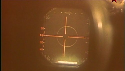
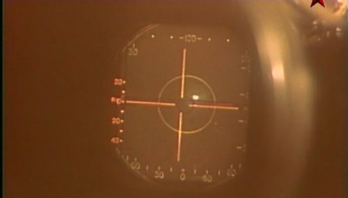
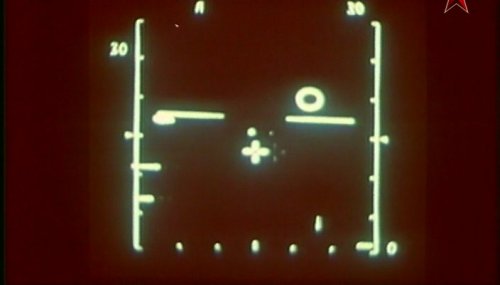
You will find some picture of the RP-25 and RP-25M in a video from a russian tv broadcast at
ftp://ftp.redrodgers.com/Video/VoennoeDelo/ (Istorija radarov VVS).
")
.Smerch-A3 more improvements, which were fitted to later model MiG-25Ps as they rolled off the production line.
True, R-40 uses a monopulse seeker. That time there was two approaches to semi active seekers. One uses continues wave illumination (or pseudo - continues). This allows in rather simply way to detect target, also on background of earth using Doppler processing. It also allows for conical scan method. It was used in Aim-7 up to version F.There is a short history of the Smerch-A series radars posted here earlier. A follow-up...
The wikipedia article on the R-40 missile claims that has a monopulse seeker. This apparently entered service on the MiG-25 in 1970. Given the state of Soviet electronics of the era, this seems somewhat questionable. I have done a bit of googling and found that most claims to this effect come from copies of the wiki article. The sole article that claims this and has its own origins is this one but I am not clear whether this is saying it was available on the first examples or some later model, the "R". The article is converted from Russian and is barely understandable in parts.
No, why? On the other hand if you have technology to put monopulse seeker, you will be able to make monopulse radar... So monopulse radars were that time in Mig-21(S and later) -23 -25...In any event, to guide an inverse monopulse missile you need a monopulse radar.
It was in many threads on this forum. Look for more details and discussion what "is" Doppler radar and what is not to for example:Most descriptions of the Smerch-A claim it to be a pulse-Doppler unit with limited look-down. This generally implies klystrons or similar (phase changes will be a PITA in the seeker). The various images posted in the earlier thread show an interesting seeker head which appears to be a dielectric lens but I can't really say. I suppose it's also possible that there was a separate illumination system, but given the range of the R-40 and the lack of any visual indication of such, I don't believe this was the case.
The Smerch-A ultimately dates to the 1950s Urgan series, and I know that even 1970s Soviet radars still often used magnetrons, which would make all of this exceedingly difficult. Its entirely possible that these capabilities were added during one of the many upgrades to the Smerch, but details I find online are all confusing.
Can anyone add some clarity here?
The wikipedia article on the R-40 missile claims that has a monopulse seeker. This apparently entered service on the MiG-25 in 1970. Given the state of Soviet electronics of the era, this seems somewhat questionable
Developed under the guidance of chief designer E.N. Genishta, the first domestic monopulse semi-active "radio" head PARG-12 used a number of new technical solutions. In particular, a two-mirror Cassegrain antenna was used to form a four-lobe directional pattern with an equal-signal deviation angle of up to 70. The GOS uses a calculator based on a sine-cosine rotating transformer, a range finder with two integrators, original circuits of a microwave generator and a receiving device with a logarithmic characteristic, which eliminates the danger of "blinding" at large drops in interference power.
In any event, to guide an inverse monopulse missile you need a monopulse radar. Most descriptions of the Smerch-A claim it to be a pulse-Doppler unit with limited look-down. This generally implies klystrons or similar
Airborne Intercent (A/I) Radar
The basic designator for the FOX FIRE A/I radar used on FOXBAT appears to be SMA. The radar processor and centralized fire control system is designated SMA 2. The circuitry of the radar processor and the fire control computer appears to be completely analog, using "peanut" vacuum tubes for IF/video with some semiconductor devices for power supply control and motor drive.
The A/I radar consists of an I-Band and a J-Band radar. The I-Band radar appears to serve as both a target tracker in range and angle as well as an illuminator for the semiactive missiles. A sample of the I-Band magnetron RF signal is sent by coaxial cable to each of the four missile pylons. A small horn is mounted on each pylon to provide this I-Band reference signal to each missile seeker head. Since there is no antenna scanning capability to allow the single J-Band feed to angle track, it appears that J-Band radar is range-only. No sample of the J-Band magnetron power goes to the pylons.
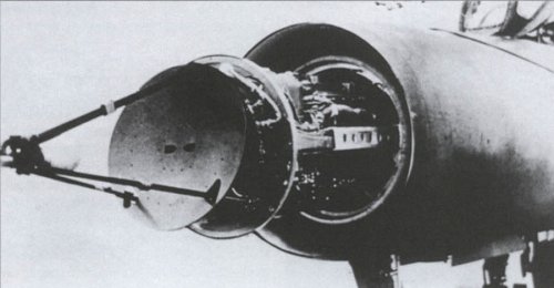
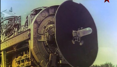
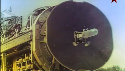
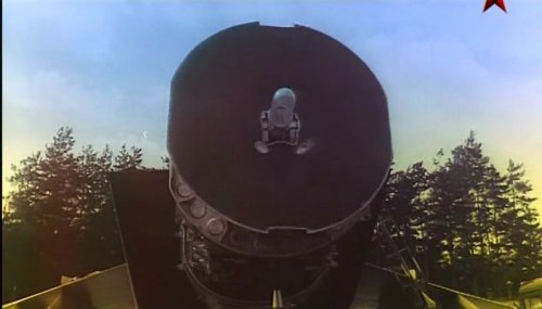
The radar antenna system contains a very complex feed system which is completely different from the simple feed assemblies seen on earlier Soviet A/I radars. The actual feed assembly is completely enclosed in a glass bell, suggestive of a pressurized system. The feed assembly contains at least four separate I-Band horns in the center with eight additional horns, probably J-Band, four on each side of the I-Band horns. These I-Band horns support the previous estimate of a LORO (Lobe On Range Only) track mode for the FOX FIRE radar. The function of these eight other horns is unknown. This new and sophisticated approach to antenna design is far advanced over known MIG-21 radar systems.
A thin layer of Radar Absorbent Material (RAM) is present on the bottom of the inner radome. The material is similar to that used on FIDDLER. It helps suppress ground clutter from side-lobe echoes. As yet there is no evidence of processing techniques which help to eliminate main beam clutter, i.e., to provide a look-down capability.
There is considerable emphasis on ECCM features, including:
- Dual, separate I/J Band systems for range information
- Dual channel I-Band angle tracking capability (specific configuration undetermined) believed capable of providing protection against amplitude modulated noise or deception angle scan rate ECM.
- An additional antenna, basically an open-ended I-Band wave guide, believed to be a side-lobe blanker. It is located directly above the primary scanning antenna.
- An additional I-Band feed system (function unknown) which consists of a two element dipole array located near the four horn I-Band tracking feeds.
- Extremely high powered magnetrons. Some components (such as the isolator) consist of two identical devices in parallel for additional power handling capability. A rough estimate of power is 600 to 800 kW for I-Band and 300 to 400 kW for J-Band.
- Countermeasures against rear-launched chaff exist and are believed to be similar to the MiG-21 SPIN SCAN radar, except a capability to handle both approaching and receeding targets has been added. The concept appears to be based on range rate determination to detect lock-on to stationary chaff.
- Tunable transmitter magnetrons. There are four discrete preset I-Band frequencies which can be changed by simply changing a receiver preselection waveguide filter and changing switch settings on the radar central processor/ synchronizer. Measurements of this filter indicate the I Band frequency is 9327 MHz. The J-Band magnetron has two preset frequencies changed by turning a screw on the magnetron.
- Dual-channel capability during tracking with the I-Band is probably accomplished by alternately lobing the four horns. This suggests that FOX FIRE has a scan-with-compression capability. The use of two RF bands would necessitate the jamming of both bands simultaneously. If only the I-Band channel were jammed, angle information would be provided by the I-Band while range information would be provided to the fire control computer by the J-Band, allowing for a missile launch.
- Since the J-Band signal may have no scan capability, and no J-Band RF energy is fed to the missile seeker, the probable function of the J-Band signal is a range-only radar.
- This raises the possibility that the pulsed J-Band portion of TWIN SCAN (carried on FLAGON E) is a range-only radar and not a missile illuminator as previously thought. Further analysis of the technology used by FOX FIRE is needed before any firm conclusions can be reached concerning the exact function of the J-Band signals.
Many thanks for providing this Information.The A/I radar consists of an I-Band and a J-Band radar. The I-Band radar appears to serve as both a target tracker in range and angle as well as an illuminator for the semiactive missiles. A sample of the I-Band magnetron RF signal is sent by coaxial cable to each of the four missile pylons. A small horn is mounted on each pylon to provide this I-Band reference signal to each missile seeker head. Since there is no antenna scanning capability to allow the single J-Band feed to angle track, it appears that J-Band radar is range-only. No sample of the J-Band magnetron power goes to the pylons.
The estimated power on the I-Band and J-Band radar magnetrons are three to four times that previously' estimated (200kw) for the FOX FIRE I-Band channel. The greater power could explain the long acquisition and extremely long missile launch ranges associated with the FOXBAT A.
Then also according to the exploitation report of Belenko's MiG-25, Smerch-A had a very complex feed with 4 I band feed horns:In the semi-active pulsed radar homing head PARG-12 of the R-40R missile, for the first time in domestic and world practice, a monopulse method of information processing and a range finder with two integrators were used, which ensured greater resistance of the seeker to the effects of amplitude interference compared to previously created heads with conical scanning. The GOS also embodied the original circuits of a stabilized microwave generator and a reference signal receiver. Unlike previously used circuits with automatic gain control, the logarithmic characteristic of the receiver implemented in this GOS eliminated “blinding” during sudden changes in interference power. The dissimilarity of the logarithmic receivers caused oscillations at the goniometer output with the so-called interperiod interference.
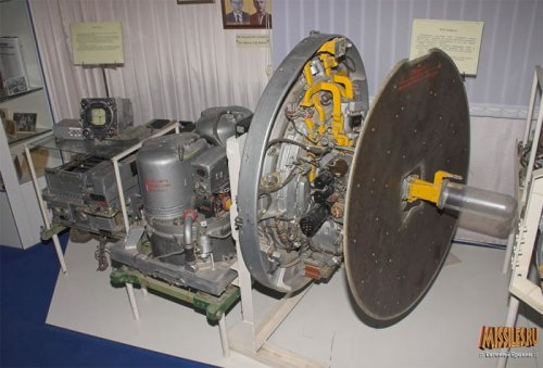
The PARG-12 head has a developed logic and high protection against interference combined with the target. A two-mirror Cassegrain antenna was used in the PARG-12 RGS to form a four-lobe directivity pattern necessary for organizing monopulse processing, as well as to ensure maximum (±70°) deviations of the equi-signal direction. The movable antenna mirror is irradiated by a stream that is stationary relative to the rocket. In this case, the equisignal direction of the radiation pattern is rotated by twice the angle of the mirror's lapel. On the basis of a sine-cosine rotating transformer, a calculator was created that converts the given overloads into a coupled coordinate system, taking into account the acceleration and deceleration of the rocket. This made it possible to build guidance according to the method of proportional navigation in the antenna coordinate system, when the projection of the full overload of the rocket on a plane perpendicular to the range line is proportional to the product of the estimated angular velocity of the range line and the approach velocity. Record bearings of the tracked target and guidance in the antenna coordinate system made it possible to intercept a high-speed target at large angles.
Therefore the antenna design is essentially similar to the Sapfir-23 or N019.The radar antenna system contains a very complex feed system which is completely different from the simple feed assemblies seen on earlier Soviet A/I radars. The actual feed assembly is completely enclosed in a glass bell, suggestive of a pressurized system. The feed assembly contains at least four separate I-Band horns in the center with eight additional horns, probably J-Band, four on each side of the I-Band horns.
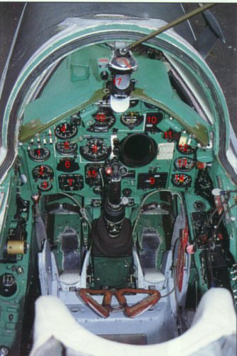
would you please tell me how did you get this picture and video from mig 25 radar display?
Captures from a documentary about the MiG-25.would you please tell me how did you get this picture and video from mig 25 radar display?
How do i can find and watch this documanturycaptures from a documentary about the MiG-25.would you please tell me how did you get this picture and video from mig 25 radar display?
An excellent article on Uragan. Can you give me your references please as I am writing a book on Soviet air defence c 1963-1972?Uragan-5B
Uragan-5B-80 RP-S /RP-28 Smerch [BIG NOSE]RP-SM Smerch-M
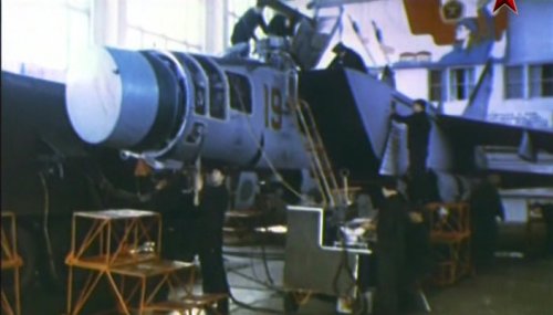
RP-25 / Smerch-A / Izdeliye 720 [FOX FIRE]
The MiG-25 used the RP-25 "Smerch-A" radar which has an interesting history. It goes back to 1954 and the Urugan-5 system, the first fully integrated and automated air defence system which was intended to counter new threats such as the B-58 Hustler. It combined multiple ground based radars and command datalinks with and an onboard radar able to detect bombers at least 25km away and capable of head-on engagements. NIIP's (Designer: F F Volkov) "Uragan-5B" radar was a major improvement on his earlier twin antenna Almaz design ("Uragan-1") and was intended to equip Mikoyan (I-75, Ye-150/152) and Sukhoi (T-37) heavy interceptors along with with K-6/K-7 (later, K-8/K-9-155/K-9-51) AAMs.
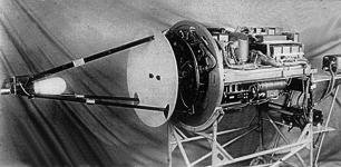
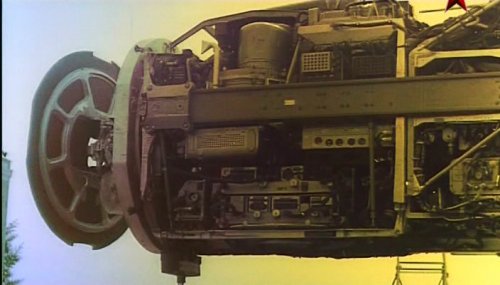
Uragan-5B was far in advance of contemporary Soviet radars, and implemented many advances in electronics and radar systems, including semi-conductors (116 vacuum tubes, 280 semi-conductor elements). It used a cassegrain antenna. It was designed as a monoblock, which slid into the nose of the aircraft and easily removed for maintenance. It was a real breakthrough in Soviet aircraft radar design. With smaller size and weight (220kg) than Almaz, it had greater jamming resistance and reliability, and detected bombers at 30km and reliably tracked them at 20km.
However slow progress with the heavy fighters, (both eventually cancelled), Uragan-5, and rapid advances in technology, meant new longer range missiles were now in development (K-80) which needed longer range radars.
NIIP by this time were redirected to SAM radar development so in 1958 Volkov was moved to OKB-339 (Phazotron) where he continued work on Uragan derivatives. Uragan-5B-80 was a major redesign for the K-80 missile, and added a new inverse cassegrain antenna with much improved characteristics (originally designed by NII-17). Detection range was increased to more than 50km and tracking range to 30-40km. This radar design was put into production for the Tu-128 as RP-S "Smerch" [BIG NOSE]
As soon as Smerch entered testing in the early 1960s Volkov embarked on another new version. RP-SA "Smerch-A" [FOX FIRE] increased detection range to 90-100km and tracking range to 50-70km. Initially intended for the Tu-128A which did not get built, it ended up equipping the MiG-25P interceptor and was retrofitted to the Tu-128 (as RP-SM) later on.
Smerch-A weighed about 500kg, was a low PRF pulse radar with inverse cassegrain antenna. It was the ultimate development of a family of radars started in 1954. A good comparison would be the F-4D's APQ-109 radar.
The Smerch-A1 as fitted to the MiG-25 prototypes introduced a second, secret operating wavelength of 2cm in addition to the standard 3cm to ensure the radar would function even in a heavy ECM environment. This was strictly prohibited from use in peacetime. By the time it entered production, improvements in jamming resistance and low-level clutter tolerance had been achieved. Smerch-A2 / Izdeliye 720M gave improved reliability, and was the standard production radar, and Smerch-A3 more improvements, which were fitted to later model MiG-25Ps as they rolled off the production line.
Around 1974 a developed "Smerch-A4" was proposed for the MiG-25-40M with lookdown-shootdown capability and R-40M missiles, but given that the MiG-31 prototype was close to first flight with the revolutionary Zaslon radar further MiG-25 developments were canned. Additionally the Sapfir-23 radar had a more promising method of clutter rejection.
N005 / Sapfir-25 / RP-25MN / S-500 [HIGH LARK]
Sapfir-25 was developed by a team under Kirpichev as a very high priority task after the defection of Viktor Belenko to Japan in 1976 compromised the MiG-25's radar making it highly vulnerable to western ECM. For speed of development, an existing radar had to be selected as the base, and the MiG-23ML's N003 radar, with its lookdown capability, was the obvious choice. Changes included the use of a larger antenna.
Detection range in lookup mode against a Tu-16 was 105-115km head-on. Tracking range against the same target was about 75-80km. Lookdown mode reduced these ranges to 27-30km and 22-25km respectively.
Detection range against a MiG-21 in lookup mode was 70km head-on, while tracking range was about 50-60km.
Weight was 337kg. It used an AVM-25 analog computer.
Compared to Smerch-A it could engage faster targets at higher altitudes, featured greater search and tracking range, provided lookdown/shootdown capability and close combat modes. It had 30° (±15deg) and 60° (±30 deg) azimuth search patterns, ±14° in elevation. It also had better anti-jamming protection. Azimuth scanning limits were slightly reduced to ±56° , elevation to +52/-42° , by the twist-cassegrain antenna design.
 www.niip.ru
In the mid-1950s, V.V. Tikhomirov managed to achieve a special resolution of the USSR Council of Ministers on the microminiaturization of electrical radio elements to create a new generation of radars. In 1958, the new Almaz-3 radar, weighing only 160 kg, successfully passed state tests and was recommended for adoption as part of the T-3 fighter-interceptor. The Almaz-3 radar had two antennas isolated from each other - a survey and an aiming one, which was natural for the "locators", but significantly complicated the life of the "aircraft".
For the first time in our country, the task of combining survey and aiming antennas was implemented on the Uragan-5B radar, which is part of the Uragan-5 interception complex. The Uragan-5B radar, designed for the E-150 interceptor, was a single monoblock container weighing 220 kg. In its design, 116 electron tubes and 280 semiconductor elements were used. In terms of its characteristics, the radar was not inferior to the best foreign analogues, having a detection range of more than 30 km from a bomber and provided stable tracking from a range of 20 km, which made it possible to use both cannon and missile weapons. Unfortunately, work on the Uragan-5B radar was stopped in the early 60s due to a change in the ideology of building air defense systems. The backlog was later used to create a radar for the MiG-25P interceptor.
Thanks to the efforts of Viktor Vasilievich and his closest associates Grishin V.K., Rastov A.A., Matyashev V.V., Sapsovich B.I. -shnyh" systems. Its distinguishing feature is a tough focus on the final result, the desire for unconditional and complete satisfaction of customer requirements. At the same time, each new development was based on advanced, non-traditional solutions, many of which were ahead of the best world achievements.
THE 'HURRICANE' THAT GENERATED THE 'WHIRLWIND'
Part II
By Andrei Fomin
Due to the complex nature of the task assigned and delays with developing
R15-300 engines and Uragan-5 (Hurricane-5) system's elements, the
resolutions of the Council of Ministers of 16 April and 4 June, 1958
reshaped the objectives and terms of building the interceptors. This time,
the following aircraft were to be submitted for testing: two E-150
R15-300-powered aircraft armed with K-8 missiles; two E-152A
R11F-300-powered aircraft armed with K-9 missiles; single E-152
R15-300-powered aircraft armed with K-9 missiles. Besides, the K-9 AAM-armed
E-152A and E-152 aircraft were to be fitted with the K-9 system with TsP-1
radar, developed by the Design Bureau-1 (now the Almaz central design
bureau) and featuring 30-km detection range, instead of the Uragan-5
intercept system's airborne component fitted with the Uragan-5B radar. The
prototypes equipped with R11F-300 engines were to begin their trials in the
third quarter of 1959. Trials of the aircraft powered by R15-300 were
postponed until the second quarter of 1960. Nonetheless, the commencement of
comprehensive testing of the on-board elements of the Uragan-5 intercept
system together with K-8 missiles in the fourth quarter of 1958 was done
owing to the I-75 and I-75F aircraft.
While the Uragan-5 system components were being tested on the I-75 and
I-75F, late November 1958 witnessed the assembly of the first E-150
prototype fitted with R15-300 engines. For the first time, the designers use
the honeycomb filler that ensured the 10%-18% reduction of weight of
ailerons, flaps and empennage while enhancing their stiffness. During the
first six months of 1959, the aircraft was undergoing ground testing
programme as well as all-mode engine testing. However, due to repeated
delays in deliveries of the Uragan-5 system components, the work on that
prototype were cancelled. Later, the E-150 was used for the flight testing
and research of the R15-300 engine capable of higher altitudes. This also
cause the cancellation of the work on the I-75 and I-75F. The whole second
E-150 prototype's technological backlog was later used to build the E-152.
The maiden flight of the R15M-300-powered E-150 was made by test-pilot A.V.
Fedotov only on 8 July, 1960. However, after the fifth sortie, the trials
were suspended due to destruction of the engine accessory gear box. On 18
January, 1961, the permission was granted for flying with a new engine
delivered on 3 December, 1960. In 1961, the flight trials resulted in 36
sorties made, speed of 2,890 km/h (M=2.65) at 20,000 m developed and static
ceiling of 23,250 m reached.
The authorisation to use R11F-300 engines until R15-300s are delivered
ensured the kick-off of the E-152A flight trials. The OKB-155 design bureau
was quick to design and submit production draft documents (June-October
1958). The E-152A interceptor was assembled in June 1959 and handed over to
undergo the factory test programme (the second E-152A prototype has been
under production until October 1959. However, later on, it was converted
into the second E-152 prototype powered by R15-300 engines). The aircraft
also featured honeycomb fillers. The first flight made by the E-152A took
place on 10 June. The prototype was piloted by G.K. Mosolov. Yu.N. Korolyov
was appointed the leading engineer. During the first six months of 1959, the
aircraft's stability and controllability were tested. The trials produced a
speed of 2,135 km/h (M=1.99) at an altitude of 13,700 m, as well as a static
ceiling of 20,600 m. Due to the abrupt deterioration of the directional
stability, further acceleration was not pursued. The K-9 weapons suite (as
part of the Uragan-5 intercept system) development was not performed due to
the delays in deliveries of some TsP-1 radar units as well as the SAZO-SPK
command-link and transponder system.
In early 1958, the OKB-134 of the State Committee on Aviation Systems (early
in 1958, the Ministry of Aviation Industry was reorganised into the State
Committee on Aviation systems - GKAT), headed by Chief Designer Ivan
Toropov, was tasked with designing the K-9 missile for E-152A and E-152
interceptors. The work was being done in cooperation with the KB-1 design
bureau of the State Committee on Radioelectronics, which was responsible for
the guidance system development. In line with the schedule, the experimental
units were expected to be submitted for the joint official testing in the
second quarter of 1960. However, in 1959, the development of the K-9
missiles was handed over to the OKB-155 design bureau. There the missile was
redesignated as K-9-155, with a design team having been set (head - V.G.
Korenkov).
The K-9-155 missile was developed as part of the K-9 weapons system. It was
intended to be an all-aspect missile capable of hitting targets from any
direction, including on the head-on and collision courses. Based on the
missile's estimated minimal kinetic load (especially close to the target
while attacking it from any aspect), it was decided to base the missile
guidance on the parallel convergence homing method. Such a method ensured
minimal angular velocity of the missile/target line. The X-shape all-moving
wing aerodynamic configuration was selected. The longitudinal control was
exercised through the all-moving wings. The roll control was exercised
through four ailerons mounted on the fixed stabiliser. The stabiliser was
fitted with four rollerons to enhance roll damping. The missile comprised
the TsR-1 semi-active radar pulse homer, APTs-18 autopilot, TsRV-1 pulse
radiofuse, HE warhead, I-60 safety/trigger device and PRD-56 single-chamber
two-mode powder motor.
For flight trials the following variants of the K-9 missile were made -
combat version (item 90); ballistic version (item 91) - to evaluate the
missile's aerodynamic and ballistic performances when flying with fixed
wings, as well to evaluate its aircraft separation safety and its engine
performances; software testing version (item 92) - to evaluate the missile's
software-controlled aerodynamic and ballistic performances and to check the
operation of the autopilot, power supply unit and pneumatic system in
flight; telemetric version (item 93) - to evaluate the operation of the
homer- and fuse-equipped missile as part of a closed system
(aircraft-missile-target) without detonating the warhead when travelling
close to the target.
In mid-1959, the OKB-155 design bureau developed and submitted for
experimental production the drafts of two K-9 variants - the ballistic and
software-controlled ones with the drafts of the rest versions having been
developed by late 1959. The plans made provision for manufacturing 32
experimental missiles in al variants (item 91 - 20 units, item 92 - 5, item
93 - 5 and item 90 - 2). By late 1959, first 6 units of item 91 had been
made, and the manufacturing of item 92 began. Before late 1960, 21 item 91s,
7 item 92s and 4 item 93s had been completed. The production of combat
versions was postponed due to problems with development and deliveries of
BR-6A telemetric stations (developer - Plant #567), UTR-13-2 signal
conditioning units, reworked APTs-18 autopilots, power supply units and òçó
(the KB-1 was responsible for everything). In 1961, 26 missiles were made
(item 90 - 3, item 91 - 6, item 92 - 11, item 93 - 6). Early in the same
year, three launches of the K-9 (item 91) missile were performed. The
launcher was mounted on the ground-based stand which simulated an aircraft
underwing launching pylon.
Since the deliveries of the Uragan-5 system's elements have been repeatedly
disrupted, in 1960 the OKB-155 design bureau took up designing the E-152-9
intercept complex intended to operate as part of the Dal automatic guidance
system. The E-152-9 system comprised an interceptor aircraft; the k-9 weapon
system comprising the TsP-1 radar and K-9 missiles with guidance equipment;
the VB-158 computer; Meteorit SAZO-SPK command-link and transponder system
(to operate as part of the Vozdukh-1 semi-automatic guidance system; in 1961
the intercept system was completely converted to operate as part of the
Vozdukh-1 semi-automatic guidance system and was redesignated as E-152-9-V);
AP-39 autopilot; KSI compass system; flight navigation aids' set (NP-1 and
PP-1), as well as a range of other systems. By the end of the year, the
automatic aircraft control and guidance system had been completed, control
circuits had been tested at the dynamic instrument test stand in conjunction
with real avionics and systems in all intercept modes the E-152A and E-152
interceptors were capable of - programmed climb, ground-controlled guidance
to the target in azimuth and altitude, homing, recovery from attack and
levelling under semi-automatic and fully automatic control. The bench tests
confirmed that the equipment provides the pilot with effective and safe
control of the aircraft in all flight modes. To ensure control circuit
dynamic stability and sighting accuracy, the TsP-1 radar elements were
reworked, as were the VB-158 computer and PP-1 flight director indicator.
Upon completion of the flight trials in August 1960, the E-152A was fitted
with the E-152-9 intercept system's components. Late in 1960, flight testing
of individual elements (TsP-1 radar, AP-39 autopilot, VB-158 computer and
flight director devices) began. Soon, the aircraft furnished with the K-9
launchers was redeployed to the Air Force Research Institute's proving
ground to carry on with trials. There, it made 39 sorties. During flight
tests in 1961, the E-152A aircraft launched 10 K-9 missiles (5 item 91s, 5
item 92s). The trials confirmed that the missile's aerodynamic and ballistic
performances had matched the estimate ones. The missile underwent wind
tunnel tests at the TsAGI, its warhead underwent ground test at the GSKB-47
proving ground of the State Committee on Defence Materiel (GKOT). The
missile systems were also subjected to preproduction and bench testing,
mathematical modelling and physical simulation in all modes, as well as a
range of other tests. Based on the warhead's ground tests and radiofuse's
flight trials, the GKAT's NII-2 research institute (currently GosNIIAS
research institute) calculated combat missile efficiency rate which
confirmed that the required performances were achieved.
Simultaneously with the E-152A development, designing and working draft
issuance on the E-150 conversion into the E-152 began in 1958. To mount
avionics and K-9 missiles on the E-152 aircraft required that appropriate
changes to the E-150 design should be made. Due to the TsP-1 radar
installation, the fuselage's fore section was stretched in length and had
its diameter enlarged too. A all-welded pressurised bay was made to house
the radar components. The bay had cooling and compressed air pressurisation
systems. The cockpit was a little bit elevated to give the pilot a better
view. The right wing housed a compartment for the frequency-matching unit of
the TsP-1 radar. The wing was also redesigned to carry K-9 missiles instead
of K-8s. As the fore section of the fuselage weight increased, a new
nosegear strut for the KT-93 660x160 mm wheel (instead of the 600x155 mm
KT-78) had to be designed. To enhance flight safety, the NP-27 emergency
pump with hydraulic accumulators had to be installed into the booster
hydraulic system. The pump was to ensure the landing with the killed engine.
Besides, the stabiliser control, previously exercised by the APS-4MK
electric device, was cancelled.
The first E-152/1 aircraft was manufactured in 1960, and its ground testing
began. On 16 March, 1961, the aircraft was sent for factory tests after it
had been fitted with the R15-300 engines. Its first flight took place on 21
April. The aircraft was piloted by test-pilot Georgy Mosolov. For the
factory tests, test-pilot Alexander Fedotov and project engineer M.P.
Proshin were appointed. Before mounting the TsP-1 radar, there was a 263-kg
counterload in the fore fuselage section. During the factory tests, which
were conducted from 16 March, 1961 till 8 January, 1962 and from 20 March
till 11 September, 1962, 67 sorties were carried out, including five ones
with K-6 missile mockups.
In that period, three world records were set by the E-152/1 aircraft which
was officially redesignated as E-166:
- on 7 October, 1961, test-pilot A.V. Fedotov set a world speed record along
a 100-km closed track. An average speed of 2,401 km/h was developed,
sometimes reaching 2,730 km/h.
- on 7 July, 1962, test pilot G.K. Mosolov set a world speed record. On the
15-25 km speed test course, an average speed of 2,681 km/h was reached in
both directions. During one of the approaches, the aircraft developed a
speed of over 3,000 km/h.
- on 11 September, 1962, test-pilot P.M. Ostapenko set a world altitude
record on a 15-25 km course, which equaled 22,670 metres with a speed of
2,500 km/h.
Meantime, the manufacture of the second E-152/2 flight prototype was
completed, and on 8 August, 1961 it was sent to the airfield for flight
trials. The suction system of the boundary layer from the air intake spike
was improved through increasing the guard net's open flow area. To enhance
longitudinal stability, the fuel consumption sequence was changed. After the
ground tests had been over, the E-152/2's maiden flight took place on 21
September, 1961. The factory tests had continued until 3 July, 1962 (test
pilots Pyotr Ostapenko (leader), Aleksandr Fedotov, project engineer A.N.
Soshin) and were cancelled following the 16th sortie due to the programme
termination, as the KB-1 design bureau was re-oriented for other tasks and
it had to stop producing autopilots, homers, power units and other finished
elements of the K-9 weapon system. Furthermore, the Air Defense development
concept was changed, with air defence missile systems having been given the
highest priority. At the same time, however, the work on the new intercept
system - S-155 - began.
In line with the directive of the Council of Ministers dated 5 February,
1962, a provision was made both to further develop the E-155
R15B-300-powered aircraft in the reconnaissance aircraft and interceptor
variants and to convert two E-152s for testing elements of the S-155
intercept system being under development. In accordance with that, it was
envisaged to fit the E-152/1 with new R15B-300 engines and carry out its
flight trials. Besides, a decision was taken to equip the E-152/2 with the
Smerch-A radiocontrol and homing system, as well as with K-80 missiles in
order to test and prepare them for the E-155P interceptor.
In 1962, a working draft was developed with all necessary drawings issued.
The work on conversion of the E-152/1 into the E-152M/1 began after the
world records had been set on it. The R15B-300 engines, featuring enhanced
thrust and an all-mode nozzles, were installed on the aircraft. Extra fuel
load was added. It was housed by three detachable grotto tanks and by the
first fuselage tank. It was envisaged to install foreplanes. Due to this,
the E-152/1 fuselage's fore and rear sections were redesigned. The work had
been finished by the end of 1962, but sub-standard engines had to be
mounted. The completion of the second prototype was also delayed due to the
lack of the engines. It was assembled only in the first half of 1963,
equipped with sub-standard engines, too, and was sent to the factory flight
testing on 14 June, 1963. The E-152M/2 aircraft was equipped with R15B-300
engines and two K-80 all-aspect homing missiles, mounted on the wing tips.
The aircraft was equipped with the Smerch-A radar with the radio
interception system, SAU-1I Polyot automatic control system with flight
navigation devices, Lazur-M command link system, RSBN-2 Iskra short-range
navigation and landing system and the KSI compass system.
The R15B-300 engine ?8, delivered in November 1963 and installed on the
E-152M/1, ensured only the ground test programme, with the engine started.
The flight trials were not carried out due to the ban on operating the
engine in the air. In 1963-1964, the flight tests failed to begin because
there were no R15B-300 flight-ready engines on hand. That is why further
work on them was cancelled, and it was the E-152A aircraft that was used for
experiments.
In 1962-1965, the E-152A interceptor was used in flight tests of the BPNV-1
programmed climb computer as well as of the SAU-1I damper prototype.
However, on 29 January, 1965, the E-152A crashed during the tests, killing
test pilot Igor Kravtsov in the process. By then, the first prototypes of
the E-155R reconnaissance aircraft and E-155P interceptor had been
undergoing flight testing.
In conclusion, it is necessary to note that the aircraft with the factory
designation E-155 was, at first, slated for operating as part of the
Uragan-5 intercept system. In accordance with the above resolution of the
Council of Ministers of 4 June, 1958, three E-155 interceptors powered by a
combined powerplant (turbojet engine + liquid-propellant rocket engine) were
to be submitted for factory flight trials in the second quarter of the 1960.
They were designed to intercept targets at an altitude of up to 30-35 km at
a 140-170 km range. Their maximum speed was to be 3,500-4,000 km/h. At the
first stage of the testing, the armament was to consist of K-9 missiles, and
further K-155 missiles. Besides, development of four unmanned reusable STOL
interceptors, designed to operate from unpaved airstrips, was planned and
produce them for tests in the fourth quarter of 1961. However, it did not
proceed beyond the conceptual design stage. Despite the fact that the
Uragan-5 and E-152-9 (E-152-9V) intercept systems were not destined to pull
the alert duty, the wealth of experience, gained from their designing,
contributed considerably to the success of further development programme.

 oborona.ru
TsKB-17 became the place where the famous scientific schools of the 20th century were born.
The work of B.I. Sapsovich in the creative, young team of TsKB-17 had a huge impact on his formation as a scientist and practitioner. Heated discussions of theoretical and practical issues of creating modern technology (and the discussions sometimes lasted until late at night), interaction with prominent scientists - all this for Boris Iosifovich became a solid base, the foundation of his future independent projects.
By 1954, the load on the staff of NII-17 and personally on V.V. Tikhomirov, accustomed to bearing personal responsibility for each of the areas of work, has grown so much that he is becoming stronger in the idea of the need to form a separate enterprise with an aviation-radar line of work. Initially, on March 1, 1955, a branch of the Moscow NII-17 was formed based on the territory of the LII named after M.M. Gromov, which a year later was transformed into an independent enterprise - Special Design Bureau No. 15 (OKB-15) of the Ministry of Radio Industry. Together with V.V. Tikhomirov transferred 379 specialists from NII-17 to the branch, who laid the foundation for a new workforce. Among them was B.I. Sapsovich, who in 1957 became the head of the antenna department.
The practical participation of Boris Iosifovich in the development and introduction into serial production of radar sights for the most mass-produced MiG-15 fighter, while still within the walls of NII-17, allowed him to gain experience not only in design, but also in organizing activities in creating modern aircraft weapon control systems. B.I. Sapsovich also contributed to the first success of OKB-15 - the completion of development and adoption in November 1955 of the Izumrud-2 radar as part of the first domestic K-5 air-to-air guided missile system on the MiG-17 fighter . When developing typical radar units to improve their reliability and simplify operation, B.I. Sapsovich led the work on the creation of antenna-waveguide systems.
The first completely independent topic of the OKB 15 team was the development of the Uragan-5B locator based on a new element base. When it was created, the most advanced achievements of radar and radio electronics at that time were implemented. And the antenna-waveguide units, designed with the direct participation of B.I. Sapsovich, and then embodied in metal, showed in the process of testing that a young, but already experienced team led by Boris Iosifovich is ready to conquer new heights. And such an opportunity presented itself very soon.
At the turn of the 1960s. work on the Uragan-5B interception system for the E-150 high-altitude interceptor was canceled. The ideology of building an air defense system has changed, but the aircraft could not yet comply with it, in particular, it was still impossible to realize a long flight in supersonic. The scientific and technical groundwork for this program was subsequently used to create the MiG-25P interceptor.