USN VFX Competition (Alternatives to the F-14)

Evil Flower said:
Does anybody know if the GD entry was supposed to have any external pylons? Tony's book only gives the reference "at least 4xAIM-7" which does sound a little small. Just wondering since I'm underway building this thing for a certain flightsim.

The "at least 4...", probably comes from the requirement in the VFX solicitations to be able to carry at least 4 AIM-7, so we can assume any design could do at least that or it would be eliminated off the bat.
 
Mark Nankivil said:
Thanks Gregory - sure is fun to hunt this stuff and I am very, very lucky to have the access I've had to the Vought Archives. And looking forward to another trip this spring!

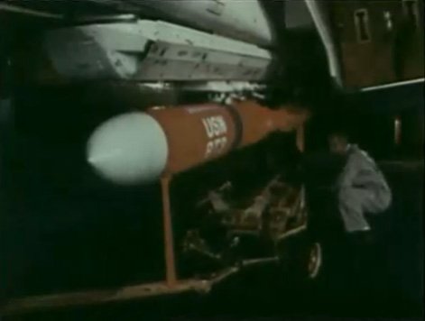
When you go any chance you could poke around for Pluto/SLAM stuff? Vought did the work on the missile portion of Pluto (called "SLAM" Supersonic Low-Altitude Missile).
 
I went looking for that info for Scott Lowther but came up short - I did not find anything missile related save for Scout and misc. aircraft launched missiles. There may be another drawer somewhere else and I'll pick up the search next time I am down there, hopefully this coming Spring.

Looking on the bright side, I at least know where it's not :)

Enjoy the Day! Mark
 
A really bad scan of NAR's VFX from an October 1968 Av week. Hopefully someone can find a better version than I did :x
 

Attachments

  • VFX-AW&ST-NAR.jpg
    VFX-AW&ST-NAR.jpg
    59.7 KB · Views: 1,047
Cool. Other artwork was posted in the start of the topic.
 
Last edited:
I wonder what was the estimated top speed of NAR's concept. Those wings don't look like they are optimized for supersonic performance.
 
I think a lot of members would be happy to see this one: I actually found the RFP for the VFX... I don't know how accurate this is so I could use to know if there were changes

- Two-man crew (tandem-seating)
- Two-engines (Pratt &Whitney TF-30 P-412 to be used as interim)
- Incorporate AWG-9 and AIM-54 Phoenix weapon system
- Carry up to 6 x AIM-54 Phoenix, or 6 x AIM-7 Sparrow, and/or 4 x AIM-9 Sidewinder missiles plus one internal M61-A1 Vulcan-cannon.
- Be designed to endure high fighter loads exceeding those of the F-4J loaded with AIM-7 Sparrow or AIM-54 Phoenix missiles
- Carrier suitability: Landing strengths for 6 x AIM-54 Phoenix missiles and 4,000 lbs of fuel. Landing speeds and weights of VFX are suitable for operations from the Hancock-Class CVA's.

There are probably other requirements too but these I remember finding online. If only I wrote down the URL.
 
Does anyone have more data about the Grumman Fixed-Wing VFX Study?

I've seen a bunch of pictures of it but very little data, particularly pertaining to wing area (and/or any data pertaining to it's performance). I could really use the data if anyone has it.


KJ Lesnick
 
KJ, was that the VFX-A or -B ? There were TWO specifications.
 
Maki said:
I wonder what was the estimated top speed of NAR's concept. Those wings don't look like they are optimized for supersonic performance.

NAVAIR doubted the performance claims of NAR's entry, they didn't think the VFX could be done without VG. The wing was also good deal straighter and less "gothic" than the FX (F-15) entry was. It's also interesting no pictures with an AIM-54 hanging off it have appeared either.

Skybolt said:
KJ, was that the VFX-A or -B ? There were TWO specifications.

Never heard of the terms of VFX-A or -B. I've heard of VFX-1, VFX-2 and VFX-3 though; the original plan the F-14A, B, C production transition plan. (http://www.flightglobal.com/pdfarchive/view/1969/1969 - 0395.html)

Here's a picture of the F-14 model after it grew a second tail with the lead designer Mike Pelehach.
 

Attachments

  • F14MP.jpg
    F14MP.jpg
    107.7 KB · Views: 1,077
Pyrrhic Victory,

NAVAIR doubted the performance claims of NAR's entry, they didn't think the VFX could be done without VG.

I didn't know NAVAIR was totally opposed to a VG-design.

Never heard of the terms of VFX-A or -B. I've heard of VFX-1, VFX-2 and VFX-3 though; the original plan the F-14A, B, C production transition plan. (http://www.flightglobal.com/pdfarchive/view/1969/1969%20-%200395.html)

How long would it take for them to go from A to C? I was always under the impression they'd go from the original TF-30 directly to the F-401?

Additionally, I was never under the impression that spot-factor relative to the F-4 was considered such a gigantic deal (It was mentioned in the article)


KJ
 
Captures from an Italian doc on the F-14

Underside shots of the mock up with two AIM-54 and AIM-7 place on the engine nacelles. Also some orange thing that I did not recognize.
 

Attachments

  • 6-belly.jpg
    6-belly.jpg
    42.2 KB · Views: 960
  • 6-sparrows.jpg
    6-sparrows.jpg
    46.3 KB · Views: 902
  • orangething1.jpg
    orangething1.jpg
    38.6 KB · Views: 907
The red one could be a Harpoon Mock up?

An Italian Doc? About what?

Why are the under engine nacelles not used like this? Is it because of little space to the deck on hard landings?
 
An Italian documenary on the F-14, made by using US videos. Probably by DELTA. I myself own the B-52 one, that you can find in original version on YouTube.
 
So there was nothing that could have been done that would have persuaded the USN that a fixed-wing would have worked?
 
starviking said:
Racer said:
The red one could be a Harpoon Mock up?

I think it's too small in diameter to be a Harpoon.
I disagree. Compare it to the inlet just to the right, which should be about the same size as the one on the F-14 we know and love. Harpoon's only a hair over a foot in diameter, and a man could crawl down an F-14 inlet if he wished.
 
Hi All -

Some photos of the McDonnell Douglas Model 225 model in the St. Louis Aviation Museum collection that match up with the post that started this thread.

Enjoy the Day! Mark
 

Attachments

  • xMG_1671.jpg
    xMG_1671.jpg
    115 KB · Views: 589
  • xMG_1670.jpg
    xMG_1670.jpg
    107 KB · Views: 454
  • xMG_1669.jpg
    xMG_1669.jpg
    140 KB · Views: 456
  • xMG_1668.jpg
    xMG_1668.jpg
    132.1 KB · Views: 932
  • xMG_1667.jpg
    xMG_1667.jpg
    155.6 KB · Views: 978
  • xMG_1666.jpg
    xMG_1666.jpg
    154.5 KB · Views: 956
  • xMG_1665.jpg
    xMG_1665.jpg
    125.9 KB · Views: 969
  • xMG_1664.jpg
    xMG_1664.jpg
    134.7 KB · Views: 1,087
This McDonnell-Douglas fixed wing FX design derivative was considered for the VFX requirement.
 

Attachments

  • xMcDonnell-VFX-fixed-wing-proposal.jpg
    xMcDonnell-VFX-fixed-wing-proposal.jpg
    106.4 KB · Views: 629
Some greatly reduced (15% of original size) snips of some Convair Model 44 diagrams I came across. The full-rez, complete versions of these may or may not wind up for sale, but for now the full rez versions are "embargoed."
 

Attachments

  • model 44 a.jpg
    model 44 a.jpg
    91.1 KB · Views: 1,806
  • model 44 b.jpg
    model 44 b.jpg
    43.7 KB · Views: 730
  • model 44 c.jpg
    model 44 c.jpg
    55.3 KB · Views: 550
  • model 44 d.jpg
    model 44 d.jpg
    31.4 KB · Views: 576
overscan said:
The cutaway drawing is particularly beautiful.

Yeah, it's a hell of a piece of artwork. The first time I saw it, it was in the form of a far-to-big-for-my-flatbed-scanner "blueprint," seen here in photo form. The next day I came across a conveniently sized version that scanned well at 600 dpi.
 

Attachments

  • IMG_9087.jpg
    IMG_9087.jpg
    61.4 KB · Views: 557
Regarding the McDD model 225, that's the only low-wing VG aircraft I think I've ever seen.

Where would the main undercarriage go? Looks like the wing pivot box gets in the way. ???

cheers,
Robin.
 
Tu-22M has low wing and VG wings.

Granted, the pivots are further outboard, but then the McDD 225 also seems to me to have larger fixed glove sections and wider spaced pivots than other VFX designs. Grumman also had a low wing VFX design, 303D.
 
That fixed wing design, was that the F-15N or another Naval FX derivative?
 
The Su-17 also has a more or less low-mounted wing with VG. In the case of the McDD 225, the pivots would seem to be in the front part of the large gloves, with the landing gear probably located in the main fuselage near the aft end of the glove. The underside of the model shows a blank spot around that point where there is only a centerline missile.

The painting don't seem to show the VG structure very well -- there's no hint of a panel line between the fixed glove section and the pivoting outer wing section.
 
Tu-22M has low wing and VG wings.

DOHH!!!!!!!!..........................Got my fighter head on! ;D

The Su-17 also has a more or less low-mounted wing with VG

that counts as mid-wing for me! ;)

Anyway, found this on page 418 of Putnam's 'McDonnell Douglas' volume 2, it shows the position of the undecarriage on the fuselage, could still do with an underside view, though.

cheers,
Robin.
 

Attachments

  • McDD model 225.jpg
    McDD model 225.jpg
    58.8 KB · Views: 860
Here's a few more additional Model 225 illustrations...

Enjoy the Day! Mark
 

Attachments

  • xMcD-D Model 225A - F-111B Size Comparison.jpg
    xMcD-D Model 225A - F-111B Size Comparison.jpg
    67.6 KB · Views: 1,068
  • xMcD-D Model 225 Internal Structure.jpg
    xMcD-D Model 225 Internal Structure.jpg
    94.4 KB · Views: 1,181
  • xMcD-D Model 225 General Arrangement.jpg
    xMcD-D Model 225 General Arrangement.jpg
    86.6 KB · Views: 1,354
robunos said:
Anyway, found this on page 418 of Putnam's 'McDonnell Douglas' volume 2, it shows the position of the undercarriage on the fuselage, could still do with an underside view, though.

cheers,
Robin.

You do realise that picture was the first post in this topic?

;)
 
OOPS !!!!!!!!!!!!

That'll teach me not to bother tracking through the thread before posting! :-[ :'(

If you want an excuse, I'll say that I was tired after trying and failing to get into the Cosford airshow, eventually finding a vantge point on one of the surrounding roads, only to have my camera pack up and cause most of my pictures to come out blurred. :mad:

Anyway, back on topic, Mark Nankivill, I see that your Model 225 3-view has 'Phantom' type intakes, rather than the wedge type shown in the other illustrations.
Would this be an earlier version? Or were the intakes changed to allow the mounting of the canards shown in the other images?

Cheers,
Robin.
 
KJ_Lesnick said:
Abraham Gubler,

If you are going to Sponge KJL at least try and ask less inane questions...

I wasn't trying to sponge, and I didn't think it was an inane question. I know spot factor is important to some extent on all Navy Fighters, I'm just wondering how big a deal it was for this particular program over others for example.

Unless you're the F/A-18, spotting factor is always a major factor. It determines how many you can carry, how many you can maintain, how you can park and store and how you can move around the deck.
 
This Feb 1969 Navy project seems to be from immediately after McDonnell-Douglas lost VFX to Grumman. Seems to be derived from Model 225. Single seat design.

Scan by Mark Nankivil.
 

Attachments

  • xD4C-58629 Feb-69.jpg
    xD4C-58629 Feb-69.jpg
    135.2 KB · Views: 1,335
Greetings All -

I spent my first day as a docent over at the Greater St. Louis Air & Space Museum and had a chance to look thru a filing cabinet I had not perused before. I found a variety of photos and these two of the Model 225 wind tunnel model were mixed in with the batch.

Enjoy the Day! Mark
 

Attachments

  • xD4E 331151.jpg
    xD4E 331151.jpg
    92.5 KB · Views: 895
  • xD4E 480648.jpg
    xD4E 480648.jpg
    88.1 KB · Views: 514
Back
Top Bottom