
You are using an out of date browser. It may not display this or other websites correctly.
You should upgrade or use an alternative browser.
You should upgrade or use an alternative browser.
US Navy’s UCLASS / CBARS / MQ-XX / MQ-25 Stingray Program
- Thread starter fightingirish
- Start date
bring_it_on
I really should change my personal text
- Joined
- 4 July 2013
- Messages
- 3,677
- Reaction score
- 3,855
One would think that since this thing is all set to change air-power, we'll probably get a press event :-\ 
- Joined
- 1 April 2006
- Messages
- 11,397
- Reaction score
- 10,315
https://twitter.com/BoeingDefense/status/943149494543241217
Boeing Shares Sneak Peek of Aerial Refueler for MQ-25 Competition
Unmanned refueling aircraft is completing engine runs, testing
ST. LOUIS, Dec. 19, 2017 – Boeing [NYSE:BA] for the first time is showing what it believes is the unmanned aircraft system (UAS) best suited for refueling U.S. Navy jets operating from aircraft carriers.
Through its MQ-25 competition, the Navy is seeking unmanned refueling capabilities that would extend the combat range of deployed Boeing F/A-18 Super Hornet, Boeing EA-18G Growler, and Lockheed Martin F-35C fighters. The MQ-25 will also have to seamlessly integrate with a carrier’s catapult and launch and recovery systems.
“Boeing has been delivering carrier aircraft to the Navy for almost 90 years,” said Don ‘BD’ Gaddis, a retired admiral who leads the refueling system program for Boeing’s Phantom Works technology organization. “Our expertise gives us confidence in our approach. We will be ready for flight testing when the engineering and manufacturing development contract is awarded.”
The UAS is completing engine runs before heading to the flight ramp for deck handling demonstrations early next year.
The Navy issued its final request for proposals in October. Proposals are due Jan. 3.
For more information on Defense, Space & Security, visit www.boeing.com. Follow us on Twitter: @BoeingDefense.
# # #
Contact:
Deborah VanNierop
Phantom Works
Work: +1 314-232-1624
deborah.a.vannierop@boeing.com
Attachments

- Joined
- 16 April 2008
- Messages
- 9,610
- Reaction score
- 14,513
http://boeing.mediaroom.com/2017-12-19-Boeing-Shares-Sneak-Peek-of-Aerial-Refueler-for-MQ-25-Competition#assets_20295_130095-117
ST. LOUIS, Dec. 19, 2017 – Boeing [NYSE:BA] for the first time is showing what it believes is the unmanned aircraft system (UAS) best suited for refueling U.S. Navy jets operating from aircraft carriers.
Through its MQ-25 competition, the Navy is seeking unmanned refueling capabilities that would extend the combat range of deployed Boeing F/A-18 Super Hornet, Boeing EA-18G Growler, and Lockheed Martin F-35C fighters. The MQ-25 will also have to seamlessly integrate with a carrier’s catapult and launch and recovery systems.
“Boeing has been delivering carrier aircraft to the Navy for almost 90 years,” said Don ‘BD’ Gaddis, a retired admiral who leads the refueling system program for Boeing’s Phantom Works technology organization. “Our expertise gives us confidence in our approach. We will be ready for flight testing when the engineering and manufacturing development contract is awarded.”
The UAS is completing engine runs before heading to the flight ramp for deck handling demonstrations early next year.
The Navy issued its final request for proposals in October. Proposals are due Jan. 3.
Attachments
DrRansom
I really should change my personal text
- Joined
- 15 December 2012
- Messages
- 701
- Reaction score
- 302
There is something odd with the aft wing / stabilizer...
Also, Boeing is clearly looking towards other missions with the UAV. The tanker UAV will almost certainly be repurposed towards other tasks, IR, ASW, etc., so winning the contract now gives the promise of missions in the future.
Finally, if the aircraft is undergoing engine tests, could this be another application of Black Diamond? Boeing would have a working plane while General Atomics just has PPT slides.
- Joined
- 1 April 2006
- Messages
- 11,397
- Reaction score
- 10,315
bring_it_on
I really should change my personal text
- Joined
- 4 July 2013
- Messages
- 3,677
- Reaction score
- 3,855
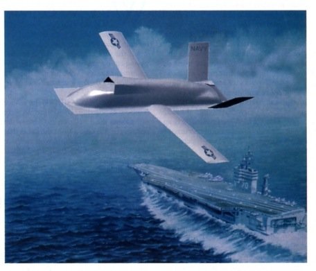
sferrin said:I think more like this: (even has the same stylized markings on the fuselage).
That was the first image that popped into my head when I looked at the teaser.

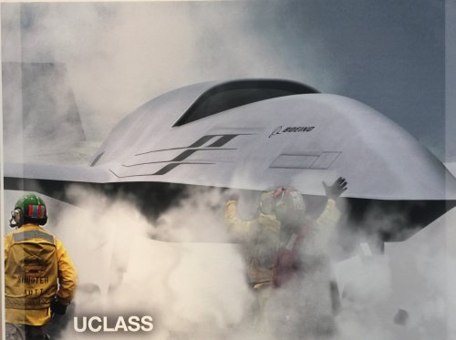
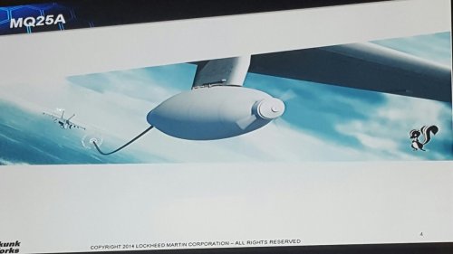
Submission of bids occurs in early January so it will be interesting to see if Lockheed sticks with their intent to retain the flying wing planform for their UCLASS design.
"At Lockheed Martin’s annual media day on March 15, AIN asked Rob Weiss, general manager of the Skunk Works advanced development unit, if the manufacturer was forced to “go back to the drawing board” as a result of the UClass program restructuring. “We haven’t gone back to the drawing board,” he replied. “What we have told some leadership of the Navy about that is we believe we can begin with a planform design that will address the Navy’s near-term desires for a low-cost primarily air refueling, limited strike/surveillance type capability. We’re suggesting that same planform can grow over time to be a penetrating strike and ISR asset. In our view, there’s no reason to start with a traditional wing-body-tail planform that will not provide the opportunity to grow it to operate in a contested airspace.”
https://www.youtube.com/watch?v=9Em14UbNUeA
- Joined
- 3 June 2011
- Messages
- 18,343
- Reaction score
- 12,248
TomS said:The left hand design seems to have gone too far in removing the engine inlet. There's still got to be one somewhere.
But yes, clearly a related design shape.
I think it's the right-hand image but the camera angle in the released picture is just low enough to hide the lip of the inlet.
- Joined
- 16 April 2008
- Messages
- 9,610
- Reaction score
- 14,513
sferrin said:TomS said:The left hand design seems to have gone too far in removing the engine inlet. There's still got to be one somewhere.
But yes, clearly a related design shape.
I think it's the right-hand image but the camera angle in the released picture is just low enough to hide the lip of the inlet.
I'd buy that.
dark sidius
ACCESS: Top Secret
- Joined
- 1 August 2008
- Messages
- 1,197
- Reaction score
- 1,070
Changing airpower with a mini tanker ?? is ambitious F-18/MQ-25 versus J-20 I make the bets
sferrin said:TomS said:The left hand design seems to have gone too far in removing the engine inlet. There's still got to be one somewhere.
But yes, clearly a related design shape.
I think it's the right-hand image but the camera angle in the released picture is just low enough to hide the lip of the inlet.
I think I can just see the red of an inlet cover over the top of the fuselage?
- Joined
- 16 April 2008
- Messages
- 9,610
- Reaction score
- 14,513
RP1 said:I think I can just see the red of an inlet cover over the top of the fuselage?
More obviously, you can see the strap that holds the inlet cover on, and the little blocks that hold the strap where it passes over the chine on the fuselage.
- Joined
- 3 June 2011
- Messages
- 18,343
- Reaction score
- 12,248
dark sidius said:Changing airpower with a mini tanker ?? is ambitious F-18/MQ-25 versus J-20 I make the bets
MQ-25/F-35C I'd take that bet. BTW you really don't like the idea of CVN tanker do you? Wait 'til it's "MQ-25/X-47B".
- Joined
- 3 June 2011
- Messages
- 18,343
- Reaction score
- 12,248
Flyaway said:That still seems a somewhat stealthy design for just a plain old tanker, must be expecting for it to be used in other roles as well.
Well they'll still want to avoid J-20s as they would be obvious targets.
- Joined
- 21 January 2015
- Messages
- 12,160
- Reaction score
- 16,376
sferrin said:Flyaway said:That still seems a somewhat stealthy design for just a plain old tanker, must be expecting for it to be used in other roles as well.
Well they'll still want to avoid J-20s as they would be obvious targets.
I assume the picture hiding the air inlet was entirely intentional for stealthy reasons.
- Joined
- 1 April 2006
- Messages
- 11,397
- Reaction score
- 10,315
Doesn't look like that, but it may be just my eyes.fredymac said:Submission of bids occurs in early January so it will be interesting to see if Lockheed sticks with their intent to retain the flying wing planform for their UCLASS design.
Attachments
raptor82 said:IIRC.......
IMO the inlet is probably still there but the low angle of the photo makes it look otherwise
- Joined
- 29 September 2006
- Messages
- 1,794
- Reaction score
- 1,360
Jemiba said:AeroFranz said:Do you know examples of V/STOL vehicles that use catapults?
No, but wasn't the naval version of the Hawker P.1154 at least intended to be cat launched ?
It certainly was, as were many British Naval VTOL projects of the 60s.
- Joined
- 4 May 2008
- Messages
- 2,439
- Reaction score
- 762
I did not know that.
I'm certain they must have calculated that there was a net benefit...that being said, i think you intuitively see that passing the loads required to accelerate a vehicle to flight speed through the landing gear is going to be heavy. Not just for the landing gear, but for the keel or longerons that transfer those longitudinal loads inside the fuselage. Conventional carrier aircraft live with it because they have to, and have higher structural weight fractions than land-based aircraft. But compared to VTOL they're not dragging around an unusually large V/STOL powerplant mass (including attitude control, nozzles, etc). As mentioned previously, V/STOL vehicles have unusually large weight growth factor (defined as pounds of extra takeoff gross weight you have to grow the vehicle in order to fit one more extra pound of fixed weight), so adding structures hurts. It is no accident that the AV-8B had some of the highest percentage of composites in its structure for its time.
So yeah, maybe you can takeoff with increased weights, but I question how much of it goes into useful load (payload + fuel), you're very much in diminishing returns mode. Not that the catapult requirement was the culprit, but the P.1154 experienced weight growth that was partly blamed for cancellation (Buttler, British Secret Projects: Jet Fighters Since 1950). Mind you, all V/STOL vehicles end up overweight...i suspect you have to be obsessively vigilant with requirement creep to be successful.
- Joined
- 21 January 2015
- Messages
- 12,160
- Reaction score
- 16,376
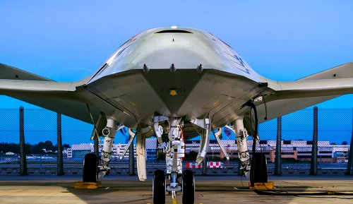
We have contacted Boeing for more images and details and they politely told us that they aren't going to release anything further until the new year. Regardless, Boeing has an outstanding and seemingly very under utilized legacy when it comes to high-end unmanned aircraft systems.
http://www.thedrive.com/the-war-zone/17086/boeing-unveils-prototype-for-the-navys-mq-25-drone-tanker-competition
Maybe it's just a big Naca air intake on the top fus, so one can't see it for that angle, like on TacitBlue,
and if it has straight wings , the conf is quite similar.
Do I see a big bay opened after the front gear ? what use of that for a refueler ?
and if it has straight wings , the conf is quite similar.
Do I see a big bay opened after the front gear ? what use of that for a refueler ?
red admiral
ACCESS: Top Secret
- Joined
- 16 September 2006
- Messages
- 1,809
- Reaction score
- 2,389
@Aerofranz
Do you think the catapult launch or arrested landing case adds most structural mass to the aircraft? I reckon its probably the landing case as there's the need to beef up the main gear for increased sink rate and add a arrestor hook, and structural mass to cope with the loads. Cat launch is pretty predictable so you can reduce uncertainty margins??
P.1154 cat launched to give higher MTOM than VTO or ski jump, i.e. increased payload range, but then VL at light weight to give all the benefits of VL recovery (lower pilot workload, heavier weather, reduced fuel mass for divert etc.)
- Joined
- 4 May 2008
- Messages
- 2,439
- Reaction score
- 762
Red Admiral, good question...i searched some of my files and while i don't have a precise answer, the attached document has a good general discussion of the topic. I removed most pages because this is a copyrighted SAWE paper and i didn't want to completely rip them off, so i kept the relevant ones. Slide number 5 seems to imply that the catapult loads on the F-14 are actually higher than the arresting or landing loads loads (am i reading that right?). Anyway, the other thing i hadn't considered is that with cat launches, the whole airframe has to be stressed for inertial loads. Could be that the airframe is already strong enough (like fighters), but it could be a sizing criteria for something non-maneuverable as a tanker. i am not sure.
The other interesting takeaway was that a more or less apples to apples comparison between a land based fighter and its carrier based twin would result in 14% higher structural fraction.
The other interesting takeaway was that a more or less apples to apples comparison between a land based fighter and its carrier based twin would result in 14% higher structural fraction.
Attachments
- Joined
- 2 August 2006
- Messages
- 3,256
- Reaction score
- 1,529
AeroFranz said:Red Admiral, good question...i searched some of my files and while i don't have a precise answer, the attached document has a good general discussion of the topic. I removed most pages because this is a copyrighted SAWE paper and i didn't want to completely rip them off, so i kept the relevant ones. Slide number 5 seems to imply that the catapult loads on the F-14 are actually higher than the arresting or landing loads loads (am i reading that right?). Anyway, the other thing i hadn't considered is that with cat launches, the whole airframe has to be stressed for inertial loads. Could be that the airframe is already strong enough (like fighters), but it could be a sizing criteria for something non-maneuverable as a tanker. i am not sure.
The other interesting takeaway was that a more or less apples to apples comparison between a land based fighter and its carrier based twin would result in 14% higher structural fraction.
Thanks for the clip from that paper as that is the first time I've seen information on the arresting loads for USAF aircraft. I also found the comments on the weight fractions for the YF-17 to F/A-18 interesting.
- Joined
- 29 September 2006
- Messages
- 1,794
- Reaction score
- 1,360
AeroFranz said:I did not know that.
I'm certain they must have calculated that there was a net benefit...that being said <Good points snipped>
I'm not sure how much of a factor the unique pegasus-type engine was seen as: no lift engines to lug around. Honestly though, I'd say that the fact that it was early days for VTOL, and that the RN was in a fight to save its carriers (CTOL) led to the adaption of cat and traps for P1154RN.
- Joined
- 21 December 2006
- Messages
- 1,245
- Reaction score
- 1,106
red admiral said:@Aerofranz
Do you think the catapult launch or arrested landing case adds most structural mass to the aircraft? I reckon its probably the landing case as there's the need to beef up the main gear for increased sink rate and add a arrestor hook, and structural mass to cope with the loads. Cat launch is pretty predictable so you can reduce uncertainty margins??
P.1154 cat launched to give higher MTOM than VTO or ski jump, i.e. increased payload range, but then VL at light weight to give all the benefits of VL recovery (lower pilot workload, heavier weather, reduced fuel mass for divert etc.)
Depends on the loads. P.1154 RN used vectored thrust for take-off too, so reduced airspeed at end of catapult and therefore acceleration loads and associated structure. On landing it could do a sort of arrested 'super' SRVL - 65kts airspeed/1.5g arrestor hook (more on twin Spey version for failed engine case). So it was stressed for both 'cats and traps' but VT limited the additional mass for both. Final RAF version also had an emergency arrestor hook (1.5g too I think) for PCB or nozzle failure conditions which added very little weight IIRC. For RN version the need to move the main wheels to the wings as outriggers would be snapped off by wires was the biggest weight change, offset by wing structure/bending relief mass reduction.....and so on. It all depends.
- Joined
- 17 October 2006
- Messages
- 2,393
- Reaction score
- 1,197
Would it have changed the 1154 picture had the ski-jump been invented earlier?
Although, looking at the evolution of the HS.1154RN, what's clearly happening is this...
"It works better with the twin engines, old boy - but since we're using the catapult and arrester hook anyway, do we still need those funny moving bits on the engine? We could blow the flaps, like the Bucc. And shouldn't we look at the J79 while we're at it? Might cost less than RR wants to charge us..."
- Joined
- 24 November 2008
- Messages
- 1,549
- Reaction score
- 2,612
Btw, https://foxtrotalpha.jalopnik.com/the-a-6-intruder-was-originally-designed-with-thrust-ve-1560922846
"...In testing, the YA2F-1's swiveling nozzles only significantly helped the aircraft get off the ground faster when it was lightly loaded, and only reduced the aircraft's approach speed a few knots. Considering the added complexity, cost and training requirements that were involved with the unique exhausts, the idea was dropped on production models..."
BR Michael
- Joined
- 4 May 2008
- Messages
- 2,439
- Reaction score
- 762
Harrier said:red admiral said:@Aerofranz
Do you think the catapult launch or arrested landing case adds most structural mass to the aircraft? [...]
Depends on the loads. P.1154 RN used vectored thrust for take-off too, so reduced airspeed at end of catapult and therefore acceleration loads and associated structure. On landing it could do a sort of arrested 'super' SRVL - 65kts airspeed/1.5g arrestor hook (more on twin Spey version for failed engine case). So it was stressed for both 'cats and traps' but VT limited the additional mass for both. Final RAF version also had an emergency arrestor hook (1.5g too I think) for PCB or nozzle failure conditions which added very little weight IIRC. For RN version the need to move the main wheels to the wings as outriggers would be snapped off by wires was the biggest weight change, offset by wing structure/bending relief mass reduction.....and so on. It all depends.
Ah, but the takeoff mass is still determined by the sum of the vertical component of vectored thrust and wing lift, proportional to the square of velocity achieved at liftoff. It stands to reason that the more you can accelerate the vehicle, the more you can lift, regardless of vectored thrust. In that case, how do you pick the best combination of increased payload vs. beefed up structure?
I guess not all elements of the tradeoff are linear, and there could be a 'knee in the curve' that was chosen by the designers. Maybe the cat loads were kept below what the structure had to be stressed for anyway (for other loads occurring throughout the mission)?
@BR Michael:
For thrust vectoring to be effective at reducing takeoff distances, you must have a reasonably high thrust-to-weight ratio. I have the explanation somewhere in Kohlman's "Fundamentals of V/STOL design". I'd have to look at the charts, but it essentially said that unless you had a T/W > 0.6, it wasn't worth bothering with it. So i'm not surprised the utility of the installation on the YA2F was marginal.
Similar threads
-
 Lockheed Martin - Multi purpose long endurance (MPLE) UAV
- Started by fightingirish
- Replies: 3
-
-

-

-
Optimized late 2020's USN (practical) Air Wing for CVN 68 & CVN 78 Class ships
- Started by Ironmiked
- Replies: 13