G

You are using an out of date browser. It may not display this or other websites correctly.
You should upgrade or use an alternative browser.
You should upgrade or use an alternative browser.
- Joined
- 11 March 2006
- Messages
- 8,625
- Reaction score
- 3,806
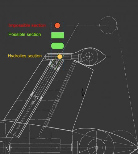
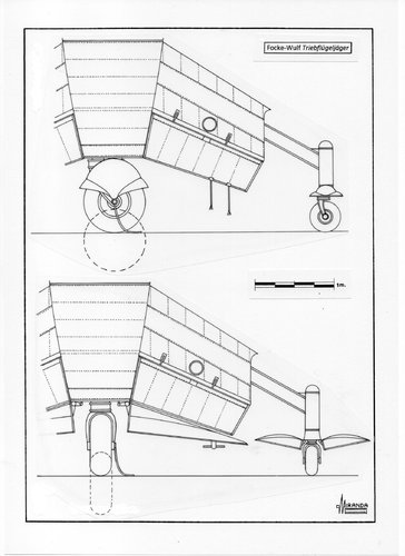
As far as I understand, you mean that the outriggers are shown too far outside, because
they would have to travel a longer distance, than the hydraulic piston can support ?
There may be a telescopic piston, but I think, you're right. The remaining question for me is,
if extending outriggers would have been necessary at all, or if long oleos wouldn't have been
sufficient to keep the Triebflügel stable on the ground .... ???
Attachments
G
gery
Guest
G
gery
Guest
- Joined
- 11 March 2006
- Messages
- 8,625
- Reaction score
- 3,806
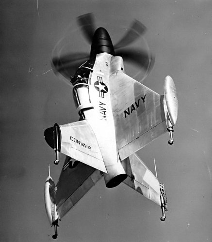
The Pogo had no outward retracting wheels and they had to carry the full weight, which
in the case of the Fw Triebflügel was the task of the center wheel, I think.
The longer the length of the extended wheel, the greater the bending loads, so your "possible
section" may be the longest length, if we discard the idea of a telescopic piston.
in the case of the Fw Triebflügel was the task of the center wheel, I think.
The longer the length of the extended wheel, the greater the bending loads, so your "possible
section" may be the longest length, if we discard the idea of a telescopic piston.
G
gery
Guest
Jemiba,
Sorry My english is very limited......i don't discard the idea of hydrolic telescopic piston...it's the only way,
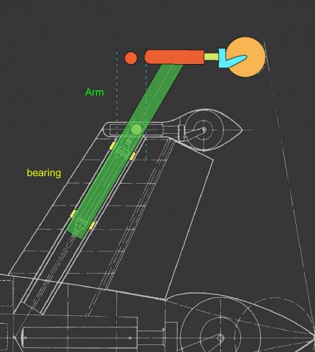
i just think that, the piston puch an arm with a more big rectangular section.....and not the small round section wich can we see on kit or renders
I don't think wich the four small wheels can make suspension (it's rigid..???)...i think just the big wheels of body
Sorry My english is very limited......i don't discard the idea of hydrolic telescopic piston...it's the only way,
i just think that, the piston puch an arm with a more big rectangular section.....and not the small round section wich can we see on kit or renders
I don't think wich the four small wheels can make suspension (it's rigid..???)...i think just the big wheels of body
- Joined
- 11 March 2006
- Messages
- 8,625
- Reaction score
- 3,806
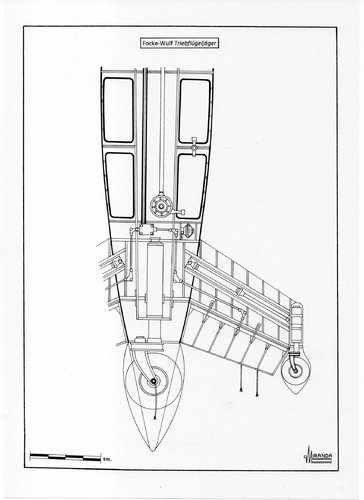
I'm pretty sure, that the outrigger wheels wouldn't have been fixed, but having a
suspension on their own. Otherwise even a landing on the smoothest surface would
lead either to the aircraft toppling down, or damaging the landing gear.
And the drawing, to my opinion shows a kind of spring-suspension, too.
suspension on their own. Otherwise even a landing on the smoothest surface would
lead either to the aircraft toppling down, or damaging the landing gear.
And the drawing, to my opinion shows a kind of spring-suspension, too.
G
gery
Guest
I think that the outrigger wheels woul have just a telescopic hydrolic piston for retrac it....and no suspension...it's clear on blue print...
taildragger
You can count on me - I won a contest
- Joined
- 2 November 2008
- Messages
- 404
- Reaction score
- 502
Assuming that the craft had to sit vertically, with all 5 wheels on the ground (which I think is safe, the CG looks like it would be fairly high and tipover must have been a concern) then all 5 wheels would need vertical travel in order to absorb the shock of landing and keep it upright over a range of gross weights.I think that the outrigger wheels woul have just a telescopic hydrolic piston for retrac it....and no suspension...it's clear on blue print...
It looks to me like the vertical travel of the outriggers was probably accommodated by building an oleo into the vertical shaft above the wheel - why else would it be larger than the diagonally extending strut (which is placed under bending, not just compressive loads)? The travel wouldn't need to be as great as that of the center wheel if the center wheel was assumed to make contact first.
Alternatively, it could be that the entire fin pivoted around the inner end of the telescoping strut. That's suggested by the fact that the diagonally telescoping strut structure seems to serve as the fin's spar. This arrangement would create problems for rudder/elevator control but the changing run length could be countered by tensioners in the cable runs or maybe it wouldn't matter if the control surfaces were unusable when the wheels were under load. There would also have to be some clearance created for the inner leading edge of the fin, but that could just be a slot in the fuselage.
Obviously, none of the above is directly depicted in the drawings.
Last edited:
Similar threads
-
-
-
 SPECIAL SALE - 48% OFF on X-37 Resin KITS ! Plus FREE KIT Bonus !!
- Started by Desert Dawn
- Replies: 4
-

-
1-48th scale X-37 SPECIAL KIT SALE !! With FREE KIT limited time offer
- Started by Desert Dawn
- Replies: 4