Quite a detailed article on the stealth design of the F-117A courtesy of the Society of Vacuum Coaters. It was posted previously by quellish in a B-2 topic, but I came across it today again and felt it needed posting.
A.C. Brown, Lockheed Aeronautical Systems Company (retired), Granada Hills, CA ABSTRACT
The two most important observables to the military aircraft
designer are radar and infrared. Because of its range, fre-
quency bandwidth and all-weather capability, radar receives
considerably more attention, and was given proportionate
emphasis in the design of the F-117A strike aircraft. In this
talk we start with some basic principles of radar returns from
canonical objects. This leads to the reasons for the basic shap-
ing design of the aircraft. Then we spend some time on appli-
cations of materials, including coating and absorbers, and also
move into high temperature effects. Attention to detail is the
principal differentiator which allows us to achieve very low
observable aircraft designs. Those areas where coatings are
important, such as canopies, will be discussed. The infrared
observable region is also amenable to improvement by coat-
ings. A brief description will be given of some of the areas of
interest.
INTRODUCTION
Design for low observability and specifically for low radar
cross-section began almost as soon as radar was invented.
The predominantly wooden DeHavilland Mosquito was one
of the first aircraft to be designed with this capability in mind.
Against World War II radar systems, that approach was fairly
successful, but it would not be appropriate today. Firstly, wood
and, by extension, composite materials are not transparent to
radar, although they may be less reflective than metal, and
secondly, the degree to which they are transparent merely
amplifies the components which are normally hidden by the
outer skin. These include engines, fuel, avionics packages,
electrical and hydraulic circuits, and people.
In the late ’50s, radar-absorbing materials were incorporated
into the design of otherwise conventionally designed aircraft.
These materials had two purposes, one being to reduce the
aircraft cross-section against specific threats, and the other
to isolate multiple antennae on aircraft to prevent cross-talk.
The Lockheed U-2 reconnaissance airplane is an example in
these categories.
By the 1960s, sufficient analytical knowledge had dissemi-
nated into the design community that the gross effects of
different shapes and components could be assessed. It was
quickly realized that a flat plate at right angles to an imping-
ing radar wave has a very large radar signal, and a cavity, simi-
larly located, also has a large return. Thus, the inlet and ex-
haust systems of a jet aircraft would be expected to be domi-
nant contributors to radar cross-section in the nose-on and
tail-on viewing directions, and the vertical tail dominates the
side-on signature.
Airplanes could now be designed with appropriate shaping
and materials to reduce their radar cross-sections, but as good
numerical design procedures were not available, it was un-
likely that a completely balanced design would result. In other
words, there was always likely to be a component which domi-
nated the return in a particular direction. This was the era of
the Lockheed SR-71.
Ten years later, numerical methods were developed which
allowed a quantitative assessment of contributions from dif-
ferent parts of a body. It was thus possible to design an air-
craft with a balanced radar cross-section and to minimize the
return from dominant scatterers. This approach led to the
design of the Lockheed F-117A and Northrop B-2 aircraft.
Over the past 15 years there has been continuous improve-
ment in both analytical and experimental methods, particu-
larly with respect to integration of shaping and materials. At
the same time, the counter-stealth faction is developing an
increasing understanding of its requirements, forcing the
stealth community into another round of improvements. The
message is, that with all the dramatic improvements of the
last two decades, there is little evidence of leveling-off in
capability. This paper consequently, must be seen only as a
snapshot in time.
RADAR CROSS-SECTION FUNDAMENTALS
There are two basic approaches to passive radar cross-
section reduction, shaping to minimize backscatter, and coat-
ing for energy absorption and cancellation. Both of these
approaches have to be used coherently in aircraft design to
achieve the required low-observable levels over the appropri-
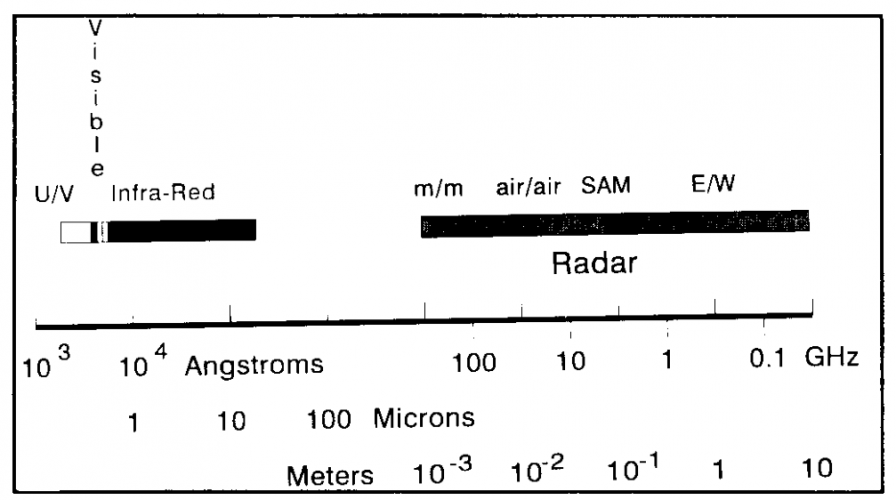
ate frequency range (Figure 1).
Fig. 1. The Electro-Magnetic Spectrum
There is a tremendous advantage to positioning surfaces so
that the radar wave strikes them at close to tangential angles
and far from right angles to edges, as will now be illustrated.
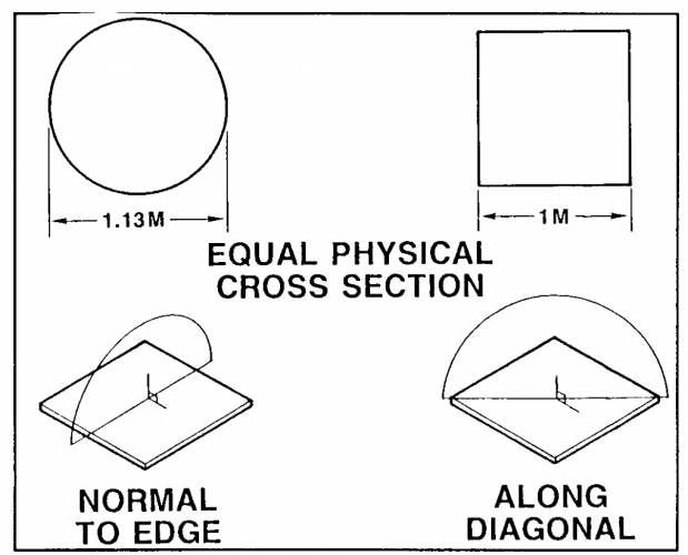
To a first approximation, when the diameter of a sphere is
significantly larger than the radar wavelength, its radar cross-
section is equal to its geometric frontal area. In the example
shown in Figures 2 and 3, the return from a one square meter
sphere is compared to that from a one meter square plate at
different look angles. One case to consider is a rotation of
the plate from normal incidence to a shallow angle, with the
radar beam at right angles to a pair of edges. The other is with
the radar beam at 45 degrees to the edges. The frequency is
selected so that the wavelength is about 1/10 of the length of
the plate, in this case very typical of acquisition radars on
surface-to-air missile systems.
Fig. 2. Radar Cross-Section - Square Plate
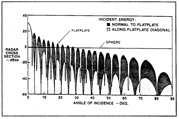
Fig. 3. Radar Cross-Section of Square Plates
At normal incidence, the flat plate acts like a mirror, and its
return to 30 decibels (dB) above or 1,000 times the return
from the sphere. If we now rotate the plate about one edge so
that the edge is always normal to the incoming wave, we find
that the cross-section drops by a factor of 1,000, equal to
that of the sphere, when the look angle reaches 30 degrees
off normal to the plate. As the angle is increased, the locus
of maxima falls by about another factor of 50, for a total
change of 50,000 from the normal look angle.
Now if we go back to the normal incidence case and rotate
the plate about a diagonal relative to the incoming wave, we
see a remarkable difference. In this case, the cross-section
drops by 30 dB when the plate is only 8 degrees off normal,
and drops another 40 dB by the time the plate is at a shallow
angle to the incoming radar beam. This is a total change in
radar cross-section of 10 million!
From this, it would seem that it is fairly easy to decrease the
radar cross-section substantially by merely avoiding obviously
high return shapes and attitude angles. However, we have not
yet looked at multiple reflection cases, which change the situ-
ation considerably. It is fairly obvious that energy aimed into a
long, narrow closed cavity which is a perfect reflector inter-
nally will bounce back in the general direction of its source.
Furthermore, the shape of the cavity downstream of the en-
trance clearly does not influence this conclusion. However,
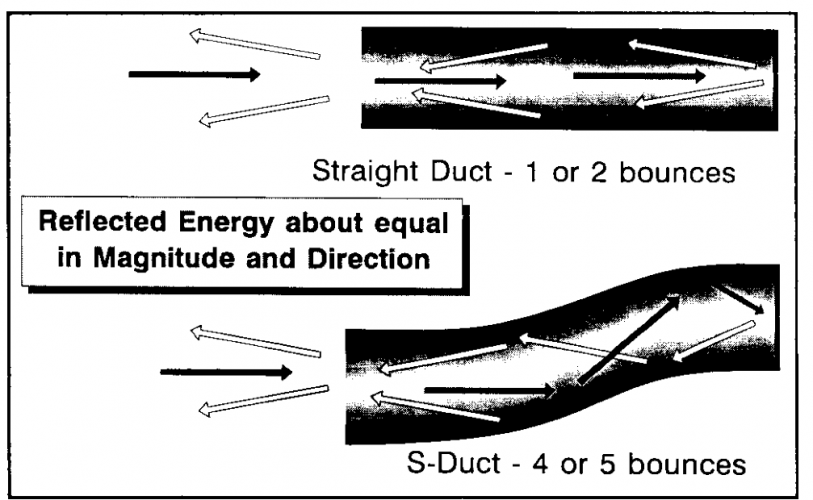
the energy reflected from a straight duct will be reflected in one
or two bounces, while that from a curved duct will require four
or five bounces (see Figure 4). It can be imagined that with a
little skill, the number of bounces can be increased signifi-
cantly without sacrificing aerodynamic performance. For
example, a cavity might be designed with a high cross-sec-
tional aspect ratio to maximize the length-to-height ratio.
Fig. 4. Energy Return From Ducts
If we can attenuate the signal to some extent with each bounce,
then clearly there is a significant advantage to a multi-bounce
design. The SR-71 inlet follows these design practices (Figure
5). Fig. 5. SR-71 Engine Nacelle
However, there is a little more to the story than just the so-
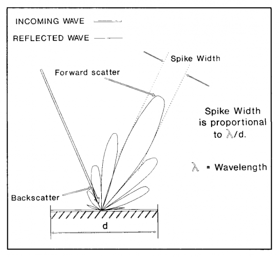
called ray-tracing approach. When energy strikes a plate that
is smooth compared to wavelength, it does not reflect totally
in the optical approximation sense, i.e., the energy is not con-
fined to a reflected wave at a complementary angle to the
incoming wave. The radiated energy in fact takes a pattern
like that shown in Figure 6. The width of the main forward
scattered spike is proportional to the ratio of the wavelength
to the dimension of the reradiated surface, as are the magni-
tudes of the secondary and tertiary spikes. The classical opti-
cal approximation applies when this ratio approaches zero.
Thus, the backscatter — the energy radiated directly back to
the transmitter — increase as the wavelength goes up, or the
frequency decreases.
Fig. 6. Typical Reflected Wave Structure
When designing a cavity for minimum return, it is important to
balance the forward scatter associated with raytracing with
the backscatter from interactions with the first surfaces.
Clearly, an accurate calculation of the total energy returned
to the transmitter is very complicated, and generally has to
be done on a super computer using finite difference or mo-
ment method techniques.
COATINGS AND ABSORBERS
It is fairly clear that although surface alignment is very im-
portant for external surfaces and inlet and exhaust edges, the
return from the inside of a cavity is heavily dependent on
attenuating materials. Referring to Figure 1, it is noted that
the radar frequency range of interest covers between two and
three orders of magnitude. Permeability and dielectric con-
stant are two properties that are closely associated with the
effectivity of an attenuating material. They both vary consid-
erably with frequency in different ways for different materi-
als. Also, for a coating to be effective, it should have a thick-
ness that is close to a quarter wavelength at the frequency of
interest. The importance of the quarter wavelength dimen-
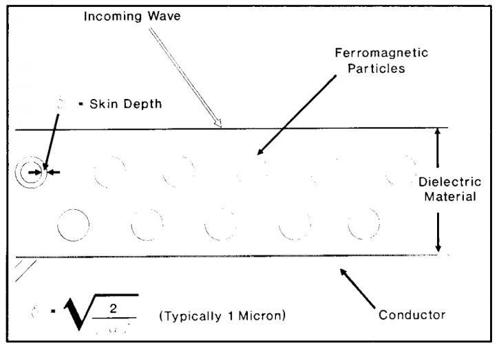
sion is illustrated in Figures 7 and 8. A typical ferromagnetic
absorber will be made of a high dielectric material, in order
to keep the thickness small, containing ferromagnetic par-
ticles, shown as solid spheres for simplicity.
Fig. 7. Typical Ferromagnetic Absorber
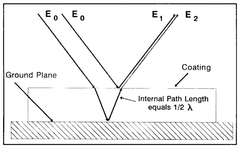
Fig. 8. Attenuation by Cancellation
The dielectric material slows the wave down, and the ferro-
magnetic particles absorb the energy. These effects by them-
selves, however, are insufficient to reduce the scattered en-
ergy to the required levels. We must now invoke cancella-
tion. Figure 8 illustrates this phenomenon. Incoming energy,
Eo, generally penetrates into the coating and most of it is ab-
sorbed. Some of the energy will reflect from the ground plane
and after further absorption, a small part, E2 escapes, having
travelled along an internal path of half a wavelength. The re-
maining energy, however, reflects off the first surface of the
material as E1. The dependence of path length on angle of
incidence is mitigated by having a high index of refraction,
which keeps the refracted ray close to the normal. Fortunately,
this is consistent with a high dielectric constant and a thin
material. It will be seen that, not only must the coating be
approximately a quarter wavelength thick, but the escaping
energy which has passed through the coating must be equal in
amplitude to that which bounces off the first surface. This will
ensure total cancellation of the returning wave, an ideal situa-
tion that is, of course, difficult to achieve.
The key dimension of a quarter wavelength can vary in prac-
tice from 1/2 millimeter to 1 meter. Although the coating de-
signer will frequently try to use materials whose dielectric con-
stant varies in a way that maintains a constant wavelength
independent of frequency, the reality is that a number of differ-
ent coatings and absorbers are needed to cover the required
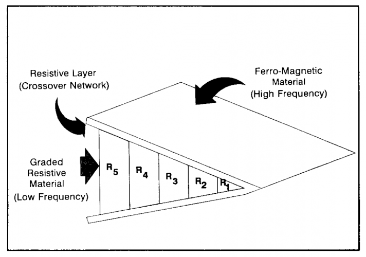
bandwidth. An illustration of this is shown in Figure 9 for a
typical edge. Here we see a low frequency absorber that might
be made of glass fiber hex-cell material. Its resis-
Fig. 9. Typical Low Observable Edge Treatment
ance is graded from front to back so that the edge is initially
electromagnetically soft, and gradually becomes more attenu-
ating as the wave passes through. This approach is particu-
larly taken when, for practical reasons, the edge cannot be as
deep as a quarter wavelength. The inner absorber is covered
by a high frequency ferromagnetic coating, which completes
the frequency coverage.
HIGH TEMPERATURE COATINGS
Reduction of radar cross-section of nozzles is also very im-
portant, and is complicated by high material temperatures.
The electromagnetic design requirements for coatings are
not different from those for low temperatures, and structural
integrity is a much bigger issue. The approach taken at
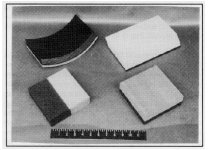
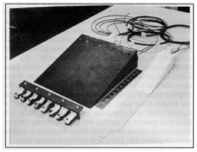
Lockheed is to use ceramic materials analogously to the low
temperature materials addressed earlier. The ceramics may
be either lightweight, parasitic sheets mounted on conven-
tional nozzle structures or heavier structural materials form-
ing cantilevered edges. Some typical examples are shown in
Figures 10 and 11.
Fig. 10. Light Weight Absorbing Ceramics
Fig. 11. Structural Ceramic Trailing Edge
In both cases, the structural design issues are thermal expan-
sion, material melting points and edge brittleness.
JET WAKES
The driver determining radar return from a jet wake is the
ionization present. Return from resistive particles, such as
carbon, is seldom a significant factor. It is important in cal-
culating the return from an ionized wake to use
nonequilibrium mathematics, particularly for medium-and
high-altitude cases. The very strong ion density dependency
on maximum gas temperature quickly leads to the conclu-
sion that the radar return from the jet wake of an engine run-
ning in dry powder is insignificant, while that from an
afterburning wake could be dominant.
COMPONENT DESIGN
When the basic aircraft signature is reduced to a very low
level, detail design becomes very important. Access panel
and door edges, for example, have the potential to be major
contributors to radar cross-section unless measures are taken
to suppress them. Based on the discussion of simple flat
plates, it is clear that it is generally unsatisfactory to have a
door edge at right angles to the direction of flight. This would
result in a noticeable signal in a nose-on aspect. Thus, con-
ventional rectangular doors and access panels are unaccept-
able. The solution is not only to sweep the panel edges, but to
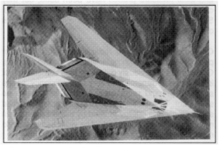
align those edges with other major edges on the aircraft. On
the F-117A, all panel edges are aligned with the trailing edge
of the wing, so that their signatures are contained inside the
basic wing signature (See Figure 12).
Fig. 12. F-17A: Edges Aligned
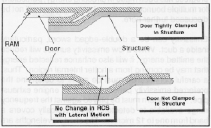
Even at that, it is important to minimize the signature of the
edges. This is done by local radar-absorbing material coating
and special shaping to minimize the effects of local cavities
and of lateral motion of doors under load (See Figure 13).
Fig. 13. Panel Edges
The pilot’s head, complete with helmet, is a major source of
radar return. It is augmented by the bounce-path returns asso-
ciated with internal bulkheads and frame members. The solu-
tion is to design the cockpit so that its external shape con-
forms to good low radar cross-section design rules, and then
plate the glass with a film similar to that used for tempera-
ture control in commercial buildings. Here, the requirements
are more stringent: it should pass at least 85% of the visible
energy, and reflect essentially all of the radar energy. At the
same time, one would prefer not to have noticeable instru-
ment panel reflection during night flying.
On an unstable, fly-by-wire aircraft, it is extremely impor-
tant to have redundant sources of aerodynamic data. These
must be very accurate with respect to flow direction, and they
must operate ice-free at all times. Static and local pressure
probes have been used, but they clearly represent compro-
mises with stealth requirements. Several quite different tech-
niques are in various stages of development.
On-board antennae and radar systems are a major potential
source of high radar visibility for two reasons. One is that it
is obviously difficult to hide something that is designed to
transmit with very high efficiency, so the so-called in-band
radar cross-section is liable to be significant. The other is
that even if this problem is solved satisfactorily, the energy
emitted by these systems can normally be readily detected.
The work being done to reduce these signatures cannot be
described here.
INFRARED RADIATION
There are two significant sources of infrared radiation from
air-breathing propulsion systems, hot parts and jet wakes. The
fundamental variables available for reducing radiation are tem-
perature and emissivity, and the basic tool available is line-
of-sight masking. Recently some progress has been made in
directing energy, particularly for multiple bounce situations,
but that subject will not be discussed further here.
Emissivity can be a double-edged sword, particularly inside a
duct. While a low emissivity surface will reduce the emitted
energy, it will also enhance reflected energy that may be com-
ing from a hotter internal region. Thus, a careful optimiza-
tion must be made to determine the preferred emissivity pat-
tern inside a jet engine exhaust pipe. This pattern must be
played against the frequency range available to detectors,
which typically covers a band from one to 12 microns. The
short wavelengths are particularly effective at high tempera-
tures, while the long wavelengths are most effective at typi-
cal ambient atmospheric temperatures. Having determined what
the required emissivity pattern is as a function of both fre-
quency and spatial dispersion, the next issue is how to make
materials that fit the bill.
The first inclination of the infrared coating designer is to
throw some metal flake into a transparent binder. Coming up
with a transparent binder over the frequency range of interest
is not easy, and the radar coating man probably won’t like the
effects of the metal particles on his favorite observable. The
next move is usually to come up with a multi-layer material,
where we use the same cancellation approach that was dis-
cussed earlier when talking about radar suppressant coatings.
The dimensions now are in angstroms rather than millime-
ters. The big push at present is in moving from metal layers
in the films to metal oxides for radar cross-section compat-
ibility. Getting the required performance as a function of fre-
quency is not easy, and it is a significant feat to get down to
an emissivity of 0.1, particularly over a sustained frequency
range. Thus, the biggest practical ratio of emissivities is li-
able to be one order of magnitude. We can all recognize that
all of this discussion is meaningless if engines continue to
deposit carbon (one of the highest emissivity materials
known) on duct walls. For the infrared coating to be effec-
tive, it is not sufficient to have a very low particulate ratio in
the engine exhaust, but to have one that is essentially zero.
Carbon buildup on hot engine parts is a cumulative situation,
and there are very few bright, shiny parts inside exhaust
nozzles after a number of hours of operation. For this reason
alone, it is likely that emissivity control will predominantly
be employed on surfaces other than those exposed to engine
exhaust gases, i.e., inlets and aircraft external parts.
The other variable available to us is temperature. This, in prin-
ciple, gives a great deal more opportunity for radiation re-
duction than emissivity, because of the large exponential de-
pendence. The general equation for emitted radiation is that
it varies with the product of emissivity and temperature. How-
ever, this is a great simplification, because it does not ac-
count for the frequency shift of radiation with temperature.
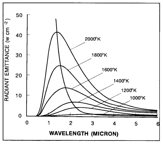
In the frequency range at which most simple detectors work,
one to five microns, and at typical hot-metal temperatures,
the exponential dependency will be typically near eight rather
than four, and so at a particular frequency corresponding to a
specific detector, the radiation will be proportional to the
product of the emissivity and temperature (Figure 14). It is
fairly clear that a small reduction in temperature can have a
much greater effect than any reasonably anticipated reduc-
tion in emissivity.
The third approach is masking. This is clearly much easier to
do when the majority of the power is taken off by the turbine,
as in a propjet or helicopter application, than when the jet
provides the basic propulsive force. The former community
has been using this approach to infrared suppression for many
years, but it is only recently that the jet-propulsion crowd has
tackled this problem. The Lockheed F-117A and the Northrop
B-2 both use a similar approach of masking to prevent any hot
parts being visible in the lower hemisphere.
Fig. 14, Infrared Radiant Energy
In summary, infrared radiation should be tackled by a combina-
tion of temperature reduction and masking, although there is
no point in doing these past the point where the hot parts are
no longer the dominant terms in the radiation equation. The
main body of the airplane has its own radiation, heavily depen-
dent on speed and altitude, and the jet plume can be a most
significant factor, particularly in afterburning operation. Strong
cooperation between engine and airframe manufacturer in the
early stages of design is extremely important. The choice of
engine bypass ratio, for example, should not be made solely on
the basis of performance, but on a combination of that and
survivability for maximum system effectiveness. The jet wake
radiation follows the same laws as the engine hot parts, a very
strong dependency on temperature and a multiplicative factor
of emissivity. Air has a very low emissivity, carbon particles
have a high broadband emissivity, and water vapor emits in
very specific bands. Infrared seekers have mixed feelings about
water vapor wavelengths, because while they help in locating
jet plumes, they hinder in terms of the general attenuation due
to moisture content in the atmosphere. There is no reason,
however, why smart seekers shouldn’t be able to make an in-
stant decision about whether conditions were favorable for
using water vapor bands for detection.
SUMMARY
The low signatures achieved by modern special purpose air-
craft are due to a combination of shaping, materials and careful
attention to detail design. Budgeting of component signatures
across a wide range of frequencies and attitude angles is man-
datory. Just as in a blackout, the game can be given away by
one chink of light.
This site uses cookies to help personalise content, tailor your experience and to keep you logged in if you register.
By continuing to use this site, you are consenting to our use of cookies.