
You are using an out of date browser. It may not display this or other websites correctly.
You should upgrade or use an alternative browser.
You should upgrade or use an alternative browser.
Shackleton-Murray Airliner Project
- Thread starter hesham
- Start date
Tophe
ACCESS: Top Secret
Re: Mr. W. S. Shackleton suggested a commercial monoplane of 1931
Thanks for this new unknown twin-boomer!
The link (that you nicely gave) explains: "this arrangement should be lighter than a normal type of fuselage, as the cabin is relatively lightly stressed."
Thanks for this new unknown twin-boomer!
The link (that you nicely gave) explains: "this arrangement should be lighter than a normal type of fuselage, as the cabin is relatively lightly stressed."
- Joined
- 26 May 2006
- Messages
- 32,639
- Reaction score
- 11,812
archipeppe
ACCESS: Top Secret
- Joined
- 18 October 2007
- Messages
- 2,286
- Reaction score
- 2,317
Re: ID this Airliner
Something by Gotha??
Something by Gotha??
- Joined
- 26 May 2006
- Messages
- 32,639
- Reaction score
- 11,812
Re: ID this Airliner
No my dear Archippepe,
I know all known Gotha aircraft and Projects ?.
archipeppe said:Something by Gotha??
No my dear Archippepe,
I know all known Gotha aircraft and Projects ?.
- Joined
- 19 October 2012
- Messages
- 1,917
- Reaction score
- 1,765
Re: ID this Airliner
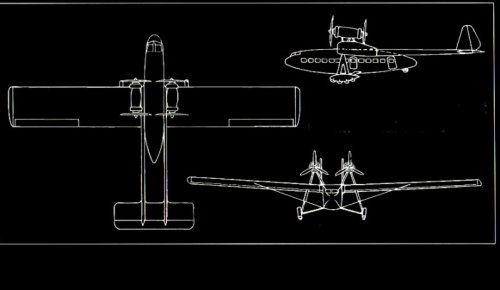
A bit of Googling the image name on Pprune says that the project had no name, just "30 seat commercial monoplane". The post says....
"William Stancliffe Shackleton, Born Australia 1896. Designer of the ANEC I,II, series of light aircraft for Air Navigation & Engineering Ltd. Then the similar Beardmore Wee Bee for that company, where he also worked on the Inflexible.
With C.L Lee Murray designed the challenge, a project for a 30 seat commercial monoplane, with the wing having some similarities with the Inflexible and the novel landing gear possibly a reaction to the huge wheel of the Inflexible, which is the sole surviving part of that design."
http://www.pprune.org/aviation-history-nostalgia/332082-silhouette-challenge-254.html
http://www.pprune.org/aviation-history-nostalgia/332082-silhouette-challenge-255.html
- Joined
- 6 November 2010
- Messages
- 4,221
- Reaction score
- 3,141
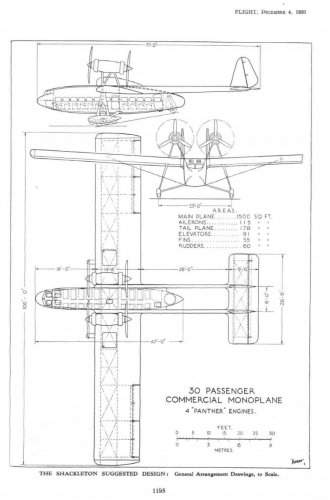
More information in the Flight archive for December 4 1931:
https://www.flightglobal.com/pdfarchive/view/1931/1931%20-%201272.html
https://www.flightglobal.com/pdfarchive/view/1931/1931%20-%201272.html
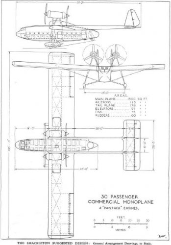
A New Shackleton Design
Departing somewhat from our usual custom, we publish below a description not of an aircraft already built, but of an interesting suggested design for a commercial aeroplane. The design is due to Mr. W. S. Shackleton, who, with Mr. Lee Murray, is now in business as consulting engineer and adviser on aeronautical matters. Mr. Shackleton, it will be remembered, was for a period chief designer to Wm. Beardmore & Co., and later went to Australia for reasons of health, there to become chief engineer to the Larkin company and Australian Aerial Services, a post which he held for four years, during which period the company's machines flew 700,000 miles without serious accident. Mr. Lee Murray is one of the best pilots Australia has produced, and in 1929 he flew a "Gipsy Moth " from Karachi to Melbourne, while this year he flew a Desoutter monoplane from Vancouver to Montreal via Los Angeles, San Diego, St. Louis and New York. While in America Mr. Lee Murray flew a large number of American aeroplanes, so that he has had practical experience of a very great number of types. Shackleton and Lee Murray, whose offices are at 175, Piccadilly (Telephone Regent 3092), mainly concentrate on work for overseas clients, chiefly reporting on the suitability of specific types, but also prepared to do any technical work, such as design and flying, reporting on flying qualities, etc. Mr. Shackleton's four-engined 30-passenger machine is of somewhat unusual conception, and he is anxious to give full credit to Mr. J. J. Davies, one of his Ground Engineers in Australia, for the outrigger scheme. Mr. Davies' idea was to build a light plane much in the same way as a motor car is constructed, using two parallel members similar to the chassis frame, on which engine, body shell and tail would be mounted. The design shown on the- next page is, of course, quite different, but Mr. Davies' outrigger scheme has been brought into the design for reasons which will be explained later. The design shows a semi-cantilever monoplane in which the four engines are mounted in tandem pairs above the wing, the tail being carried on outriggers and the fuselage abbreviated to a large nacelle. The designer is of the opinion that this arrangement should be lighter than a normal type of fuselage, as the cabin is relatively lightly stressed. Moreover, it is the intention that the design should be capable of a variety of uses, even including the substitution of a boat hull for the nacelle. In that case, the use of the tail outriggers would, it is claimed, get the tail surfaces well clear of the water without that up-curved stern portion of the flying boat hull which Mr. Shackleton considers to be an expensive and un-mechanical structure. Although the design shown represents a passenger carrying aircraft, Mr. Shackleton points out that the design has been so planned that the general lay-out should be equally suitable for a military machine such as a bomber. In the latter form the compact cabin and tail outrigger design should give an exceptional field of view and fire rearwards, both above and below the cantilever tail. From the cabin the view is good in all directions. As a troop carrier, if unarmed, the machine would be suitable practically without alterations. As a flying boat or amphibian the hull design would be altered to provide the usual vee bottom, steps, etc., but otherwise the general lay-out could remain very much as it is. To deal with the design as it stands, the placing of the engines has been chosen because the arrangement gives a very small turning couple in the event of failure of one engine, while the obstruction to view from the cabin is avoided and noise is reduced to a minimum. The machine is intended to be of all-metal construction, and the cabin portion or nacelle would be a sort of coach-built affair, light in weight because it is not heavily stressed, and relatively cheap to build on account of the type of construction planned.
The tail-carrying outrigger arrangement was chosen for several reasons. One advantage is that by having the tail supported at two points well spaced, the tail can readily be made a cantilever without becoming heavy. The tail is so mounted on the outriggers that the tailplane spars stiffen the outriggers against torsional loads induced by the fins and rudders. It is intended that the outriggers should be of a construction identical with that of the main wing spars, so that the principal component parts would be interchangeable. The maximum bending moment in the outriggers is found to be approximately the same as that in the wing spars, a fact which helps to make possible the use of similar parts. The front and rear main wing spars are identical and are connected by bulkheads at intervals and double-braced on top and bottom of the bays. This arrangement stiffens the wing considerably against torsional loads, and results in similar deflection of both spars under load. The outrigger spars are attached to the cabin, and the wing halves are secured to the outriggers, from which they are detachable. It will be noted that the wings are wire braced below, i.e., that they have lift wires but no antilift wires. The system has a minimum of air resistance, reduces structure weight as compared with a pure cantilever wing, and enables parallel wings to be employed, thus reducing manufacturing costs. No anti-lift wires are shown in the general arrangement drawings, but in the event of stressing requirements calling for heavy down loads wires could easily be added on top. They would then be taken from the same bracing points as the lift wires, and would run to the centres of the engine nacelles, and with additional wires joining the port and starboard nacelles. An interesting innovation is to be found in the design of the undercarriage. Instead of a single large wheel on each side, there is a wheel unit consisting of four smaller wheels (with tyres of the low-pressure type) mounted inside a stiff duralumin casing of streamline shape. This casing is free to pivot on the main axle, and an inverted vee strut unit with two shock absorber struts provides the springing as well as automatically limiting the amount of "rock." The advantages of this type of undercarriage should be low air drag, a minimum of two wheels in contact with the ground, and, under heavy loads, three, or under certain ground conditions four wheels, so that the machine should be safe on sandy or muddy soil, and under heavy braking conditions. Another advantage, arising out of the caterpillar-like wheel arrangement, is that nosing over should be very unlikely to occur since if the machine tips on to the front wheels the point of contact is well forward. It is not thought that the weight of this type of undercarriage should be appreciably greater than the weight of a normal type. The tail wheel arrangement is, like that of the main undercarriage, unorthodox. The wheel is mounted in a cone on radius rods, and is free to rotate through 360 degrees. The shock absorbing strut of the tail wheel is connected to the top thrust bearing of the cone. It will be seen that only a little more than half of the wheel is exposed, so that the drag should be low. Under purely vertical loads there should be very little bending in the axle as the shock absorber struts are taken to points almost vertically above the areas in contact with the ground. When the machine is turning, or if it lands with a certain amount of side drift, considerable moments in a horizontal plane could be transmitted to the axle, and when running on the ground with tail up or tail down there would be "toeing in " and "toeing out " of the undercarriage. The designers have, however, looked into these problems very carefully, and they are satisfied that these conditions can be allowed for without excessive axle dimensions or increase in weight. The power plant which Mr. Shackleton has foreseen tor his 30-passenger machine are Armstrong-Siddeley "Panthers," and it will be observed that he proposes to make use of such modern aids to drag-reduction as Townend rings. In other respects also the Shackleton machine is a remarkably "clean" looking design, and for the wing loadings and power loadings estimated it would seem likely that the calculated top speed of 160 m.p.h. should be attained. Mr. Shackleton estimates that the cruising speed at 3,000 ft. should be approximately 130 m.p.h., which would be a great deal above the cruising speeds of any commercial machines we have in service at the present time. The calculated tare weight of the machine is 13,120 lb., and as the machine is stressed for a gross weight of 23,070 lb., the estimated disposable load becomes 9,950 lb. As the wing area is 1,500 sq. ft. the wing loading becomes 15.37 lb./sq. ft., which Mr. Shackleton calculates will give a landing speed with full load of 62 m.p.h. This is a figure considerably above what we are accustomed to, but, on the other hand, with a power plant consisting of four engines, there should be. little risk of a hurried forced landing having to be made, so that what with the chance of picking a suitable held and the use of the special undercarriage fitted with effective brakes, a landing speed of this order might be tolerated. For a gross weight of 23,000 lb. the power loading with four engines running at maximum power is 10 lb./h.p. With one engine out of action this becomes 13.3 lb./h.p., and with two engines stopped the power loading is 20 lb./h.p. With a wing loading of more than 15 lb./sq. ft. it seems a little doubtful whether the machine would keep up on two engines, but its rate of descent should at least be very slow, and with three engines running, especially in view of the placing close together of the engines, flying on should present no difficulty. It is estimated that the initial rate of climb will be 1,100 ft./min., and that the ceiling should be about 19,000 ft.
Attachments
Similar threads
-
 Handley Page Bulletin Amazing Airliner Project
- Started by hesham
- Replies: 5
-
The Alula wing design and its applications
- Started by hesham
- Replies: 37
-
General Development Co. twin boom heavy transport aircraft
- Started by hesham
- Replies: 41
-
-