- Joined
- 22 January 2006
- Messages
- 4,392
- Reaction score
- 2,674
While waiting for Orionblamblam posts I'd like to post this beast from Hiller
(Vertical Challenge. The Hiller Aircraft Story from Jay P. Spenser. ISBN 0-295-97203-3)
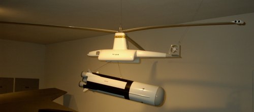
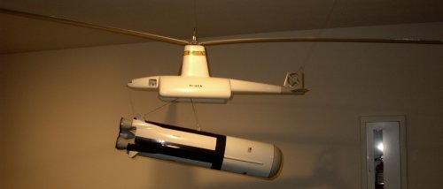
Formally proposed in 1965, it was designed to retrieve spent 200 ton Saturn V booster first stages. This tip-jet powered helo had a rotor 300 feet in diameter. Gross weight of one million pounds.
more from Stargazer2006
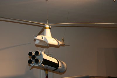
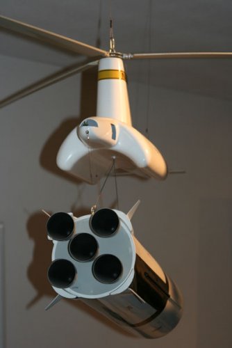
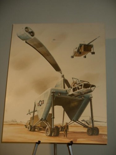
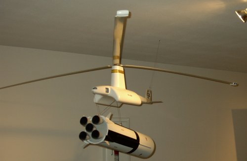
Finally, some light on the Hiller/NASA crane designed to recover Saturn V boosters (Model number unknown):
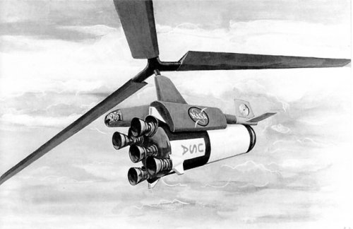
An artist's view of the Hiller/NASA crane proposal.
(Vertical Challenge. The Hiller Aircraft Story from Jay P. Spenser. ISBN 0-295-97203-3)
Formally proposed in 1965, it was designed to retrieve spent 200 ton Saturn V booster first stages. This tip-jet powered helo had a rotor 300 feet in diameter. Gross weight of one million pounds.
more from Stargazer2006
Finally, some light on the Hiller/NASA crane designed to recover Saturn V boosters (Model number unknown):
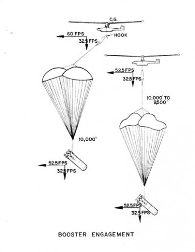
Company hopes for giant tip-powered helicopters revived briefly in 1965 when the National Aeronautics and Space Administration considered sponsoring a Hiller flying crane to recover Saturn V moon booster first stages during Project Apollo. Aerial recovery of this spent first stage, which weighed up to 400 tons, dictated that the Hiller/NASA recovery vehicle be the largest aircraft of any kind yet proposed. The resulting design featured a gross weight of about a 450t and a rotor more than 100m in diameter. Powered by two or more jet engines per blade, this rotor would have turned at 60 rpm, presenting the illusion of slow motion to observers below.
As laid out, the Hiller/NASA flying crane would loiter at 3000m some 750km downrange from Cape Kennedy. Sighting the moon booster descending by parachute, it would use special recovery gear to snag the spent rocket and winch it securely in. If the first pass was unsuccessful, sufficient time would remain for two more attempts before the booster was too near the ocean's surface for another try.
Expensive as such a helicopter would have been, the huge aircraft would have paid for itself with the first several recoveries. But long-range planning for the nation's space program was beginning to favor the concept of a reusable space shuttle over single-use rockets, and this recovery helicopter was not funded.
An artist's view of the Hiller/NASA crane proposal.