Podded engines/intakes and wingroot intakes. can they still be relevant today?

helmutkohl

ACCESS: Top Secret
Staff member
Senior Member
Joined
29 November 2010
Messages
1,684
Reaction score
3,164
I wanted to take about aircraft design, especially on two types of configurations that are not as popular as they once were.
perhaps some of our aerodynamic experts here could give better details

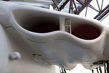
Wingroot intakes, especially popular in the UK
could they still be useful in tactical combat aircraft of today?
I recall reading the main issue with them was related to increasing need for speed caused boundary layer separation issues that saw the design being stopped but not sure

220px-Valiant_2_%283446560911%29.jpg
images


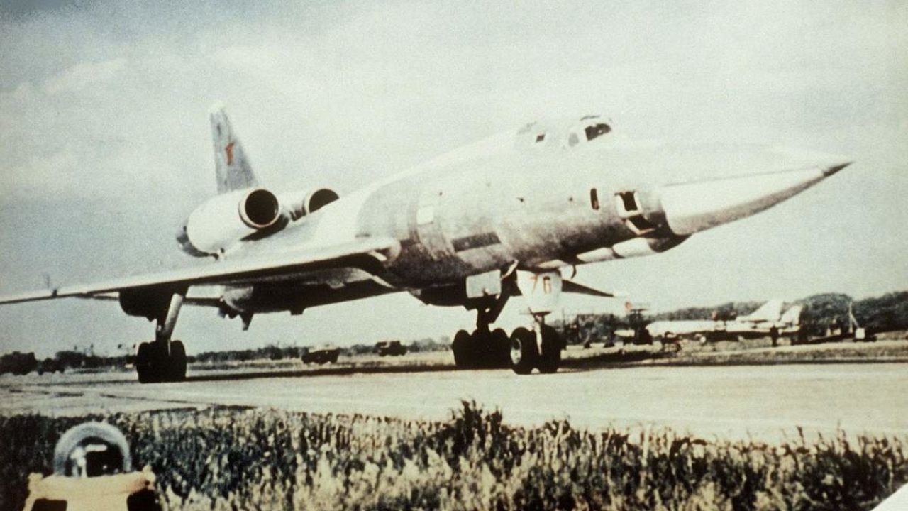
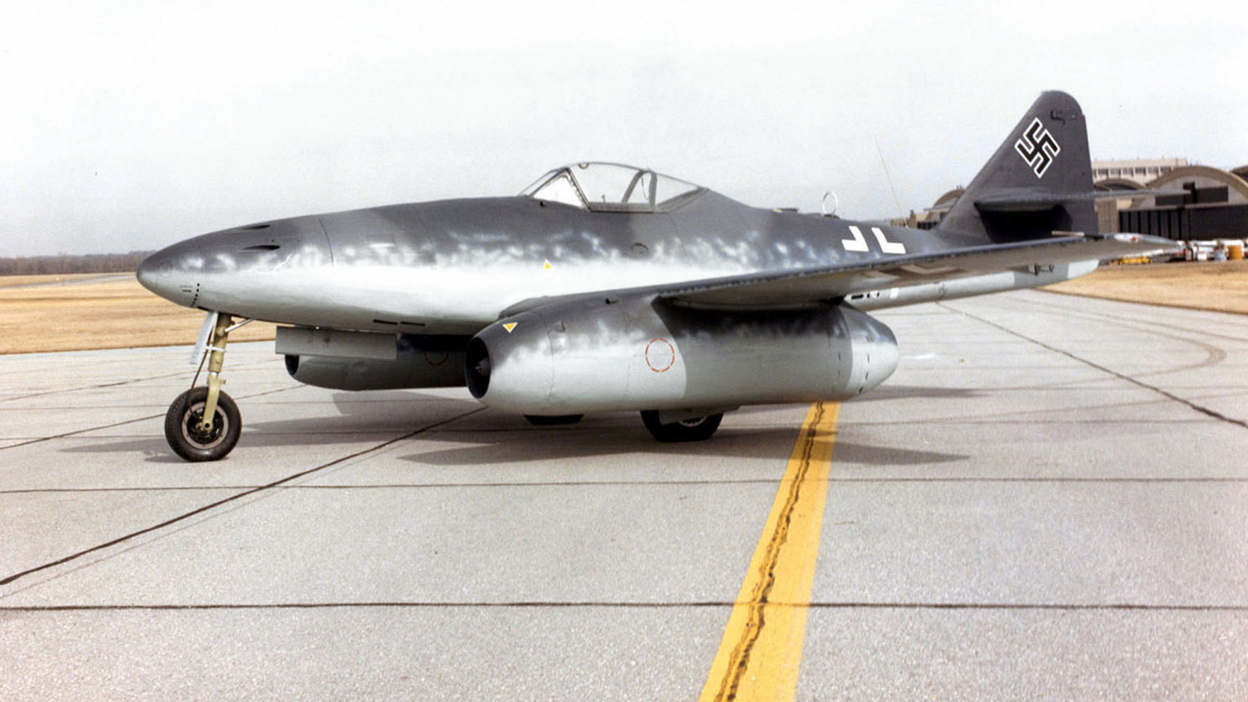
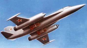
Podded intakes and engines. more common in the cold war period, but apparently I just learned Yak even had a 4th gen design ready.
Still in use with transport aircraft and some bombers, but are their days on tactical combat aircraft over?
Messerschmitt_Me_262A_at_the_National_Museum_of_the_USAF.jpg

yak45-i.jpg
 
Last edited by a moderator:
Wing root intakes are fine if you don't need continuous high alpha performance. The Draken could perform some excellent high alpha maneuvers, but they were only instantaneous. There are many stealthy cargo plane designs on this site that feature that system, because you want the propulsion buried in the structure for stealth. If you don't need stealth, the podded engines below the wings are better, because they counteract the natural pitching moment developed by the wing and that allows the wing to be made lighter for higher performance, such as on all modern commercial airliners. Podded engines also have easier access for maintenance.

The problem with podded engines for interceptors and fighters is they create large outboard masses that are harder to start and stop rolling, so they are a drawback to agility. There's also the problem of engine out yaw issues; meaning you're going to need a larger vertical tail, which is more mass and drag, which leads to a bigger wing, which is more mass and drag and that all adds up to more expense. Also, they increase the surface area, which is more drag. Having said that, they tend to be in clean uninterrupted airflow, which was more of an issue for early jet engines, since they didn't handle flow distortion that well. For commercial SSTs where they are located under the wing, the shock interaction with the wing can lead to a higher L/D at supersonic speeds.
 
The other thing about having your intakes (and in the case of the Comet, engines) in the wing root, is re-engining will be a major chore. It's (more) difficult to modify an intake for the airflow demands of a particular new (probably larger thrust, massflow) engine if one is constrained by squeezing it into an existing structure.

Pods are easier to manage in that regard, but I'd be hard pressed to give you a good reason for putting engines outboard on a fighter aircraft if agility is a concern. If the engine is embedded in the wing, we have that disadvantage along with again being constrained to structure.

You had several ATF concepts from Lockheed and Boeing (that were more supercruise interceptors than fighters) which had outboard engines. Even some compression lift concepts with podded engines.

Podded engines would also greatly complicate signature management. Embedded in the wing root or wing would be easier to manage, but also difficult.

You would need a requirement that prioritizes something other than agility, signature, and possibly growth potential, and that doesn't really sound like modern or future tactical aircraft.
 
Don't forget that engines are more compact today. Having inlets buried in the leading edge will involve having an aft positioned wing to keep ducting length (hence weight and drag) at bay.

On the contrary, most supersonic design will have somewhat podded engine nacelles. It ease design when it comes to structural and transonic form drag.
 
A significant issue with wing root engines is the landing gear. With wing root engines the landing gear is normally outboard and retracted into the wing structure. This means it’s difficult thin main landing gear (Valiant) or the wing is fattened up (Comet) to act as a fairing. The fatten wing is nearly a symmetrical section over the landing gear length ie no Lift. Using the wing this way amounts to a very expensive/heavy faIring. Also the landing gear is a very stiff piece of structure which needs to be accommodated in a inherently flexible wing, .....does the fun never end.

Another way to do it is as per the Tu16 or Valiant B2 whereby the landing gear is is stowed in carats behind the trailing edge. Big reverse torsion on the wing hence becoming its sizing case in this axis. That said this is probably the best way to do it.
 
Leading edge intakes were introduced during WW2 to reduce boundary layer turbulence. Even piston-powered DH Mosquito and Hawker Tempest used leading edge inlets for radiators and oil coolers.
Even today, pod-mounted inlets are still the easiest way to avoid ingesting boundary layer air, which is why they dominate the civilian airliner market.

When first-generation jet fighters moved intakes to fuselage sides, they started experiencing problems with turbulent boundary layer air causing engines to surge. The first solution was vented ramps to divert BLA away from intakes (see. F4 Phantom and FA-18 Hornet).
Meanwhile, Lockheed developed fixed cones to divert supersonic shock waves away from intakes (see Lockheed F-104 Starfighter). Modern F-35 also uses fixed intake cones to divert shock waves and slow inlet air to sub-sonic speeds before it hits the compressor face. A secondary benefit of long intakes is that it reduces fan noise and radar signature of fan blades ... for stealth. Most modern combat jets have S-shaped inlet ducts to conceal compressors from enemy radar.

Yes, curved inlets are far more heavy and complex to build. OTOH, engines are installed far enough aft that all the hot and heavy after-burner components are as short as practical and installed as far aft as possible (see F-16 and F-18). If after-burners cannot be installed in he extreme aft fuselage (usually for balance reasons) tail feathers are mounted on booms that extend aft of after-burners (see F-15 and F-35).

Speaking of balance, early jet engines were so heavy that they needed to be mounted near the airplane's centre of gravity (see T-33 and F-86 Sabre). Replacing the engine on a first-generation jet fighter required un-bolting the entire aft fuselage to replace the engine. The worst case was Harrier jump jet, which required removing the entire wing to replace an engine!

More modern jet engines are more powerful, meaning that they are a smaller fraction of the total weight of the airplane. These more powerful engines also allow they to carry more guns ,radar, fuel, etc. That extra equipment can be mounted farther forward to balance the engines, which can now be mounted farther aft. Mounting jet engines aft of the wing allows them to be removed via simple belly access panels.

In conclusion, inlet design is just one of the many compromises made in determining where to install engines. You also have to consider turbulent boundary airflow, balance, wign structure and after-burner configuration ... a long and complex series of compromises. Future combat aircraft will continue to experiment with a wide array of leading edge, top surface, etc. inlets to maximize stealth, airflow at high alpha angles, etc.
 
Last edited:
Podded engines at the back of the plane seem to have been popular in the 1950s-1970s period. In commercial aviation you have the Caravelle, Trident, VC-10, BAC-111, DC-9 and Boeing 727; the most obvious military application being the Tu-22.

Tupolev-Tu-22-1280x720.jpg


I can see that this provides more flexibility, in that you can fit 2, 3 or 4 engines to meet requirements, and you don't have the uneven thrust problem of wing-mounted engines should one fail. In fact, a MRP might have made sense in that one or two engines could be shut down for low-speed cruising.

In commercial terms, rear jets can provide a quieter cabin - I gather the VC-10 was famous for this.
 
Last edited:
I doubt that they are relevent in the days of stealth. Pretty obvious detection wise.
 
I doubt that they are relevent in the days of stealth. Pretty obvious detection wise.

on a related note, how effective are those blockers? like the one the X-32 reportedly used since it didn't seem to have any kind of s-duct and was more or less straight through like a podded intake-engine combo
 
This early LM NGAD from 2012 concept featured wing root intakes, but they didn't appear in subsequent iterations.View attachment 639726
I think the primary driver behind this is to simplify internal layouts. This reduces how drastic the S shape ducts gonna be which usually screws up with alot of other things. The drawback I can see immediately is RCS. This layout create interrupted surfaces from both top and below. I think the idea was to start with something that simplify internal layouts to control size creep then try to work out the drawbacks of the specific design. Subsequent released images probably indicated they didn't like the trade offs
 
Wingroot intakes are aerodynamically the ideal solution for the coolers of a piston engine (see e.g. the Republic Rainbow) because they enable undisturbed air ingestion and avoid any increase in surface or frontal area. The problem with this solution is in my view, that the coolers should ideally be placed in the wing and here they will interfere with the wing spar (and the fuel tank).

For the current small watercooled aero engines (e.g the Continental Diesels), the plane builders shurly prefer a solution were all the engine stuff is a compact unit (power egg) without mayor design changes. The Diamond 50RG could have been made this way, because it is only available with one engine type, but the Diamond layout with two wing spars can hardly be combined with a cooler in the wing.
 
Integrating the coolers into the wings also allows the combination of a split flap and cooler flap. The Me109 f had something a bit like that, but combined it with an upper cooling flap (http://109lair.hobbyvista.com/techref/systems/cooling/f_flaps.htm). I'm not totally sure why it was done this way, but I believe because it allowed separate control for the cooling and landing flaps. I think, it would have been more efficient without the upper flap and the lower flap used for both functions, but with the control technology of its time this would probably caused other issues. When the lower flap serves as cooling flap, the only side effect is, that you increase lift a bit when more cooling is necessary and that you intensive the cooling during take off (that’s good) and landing (not so good, but acceptable).

Note the very short diffusor for the cooler, this was surly a side effect of the wing spars being in the way. Without mechanical restrictions, an intake at the leading edge would have been the aerodynamical more efficient solution and eliminated the need of a boundary layer duct.
 
Integrating the coolers into the wings also allows the combination of a split flap and cooler flap. The Me109 f had something a bit like that, but combined it with an upper cooling flap (http://109lair.hobbyvista.com/techref/systems/cooling/f_flaps.htm). I'm not totally sure why it was done this way, but I believe because it allowed separate control for the cooling and landing flaps. I think, it would have been more efficient without the upper flap and the lower flap used for both functions, but with the control technology of its time this would probably caused other issues. When the lower flap serves as cooling flap, the only side effect is, that you increase lift a bit when more cooling is necessary and that you intensive the cooling during take off (that’s good) and landing (not so good, but acceptable).
More lift means you can fly slower without stalling.
 
Sure, but it could mean that the balance of the plane changes slightly with the amount of cooling.
 
It might be a far stretch, but has anyone put cooling equivalent in a vertical stabilizer (tailfin)?

No fuel there. Some fins have been mounted atop wings...might a fin be a radiator? Keep fluids cool and keep that surface ice-free as a two-fer.
 
"...in a vertical stabilizer (tailfin)?"

Um, IIRC, some of the pre-war Schneider Trophy racers, used their float-struts and float topsides as cooling surfaces...
 
It might be a far stretch, but has anyone put cooling equivalent in a vertical stabilizer (tailfin)?

No fuel there. Some fins have been mounted atop wings...might a fin be a radiator? Keep fluids cool and keep that surface ice-free as a two-fer.
He-100 had surface cooling on the tail
Buggati 100 had ducts to a cooler in the tail LE
 
It might be a far stretch, but has anyone put cooling equivalent in a vertical stabilizer (tailfin)?

No fuel there. Some fins have been mounted atop wings...might a fin be a radiator? Keep fluids cool and keep that surface ice-free as a two-fer.

Adding fins to a surface would have increased drag quite a lot, bit generally this is a decent idea. One drawback is, that the stabelizers are usually far away from the engines and much thinner than the the main wings, so there is hardly enough space for coolers.

For keeping the surfaces ice free, it might be an option to use the wing tips as radiators, I had the same idea, but I''m not sure if it would work or if the ice would simply form behind the heated wing tips.
 
"...in a vertical stabilizer (tailfin)?"

Um, IIRC, some of the pre-war Schneider Trophy racers, used their float-struts and float topsides as cooling surfaces...
ISTR that the S.6 and S.6B had the oil tank in the fin, which helped with the oil cooling.

cheers,
Robin.
 

Similar threads

Back
Top Bottom