The biplane fighter reached its peak during the 1930s.
Czechoslovakia built the Avia B-534, Belgium the Fairey Firefly, Italy the Fiat CR.32, The Netherlands the Fokker D. XVII, France the Spad 510, England the Hawker Fury Mk. I, United States the Grumman F2F, Germany the Heinkel He 51, Japan the Kawanishi Ki.10 and the USSR the Polikarpov I-15.
But before the end of the decade, they were all obsolete, the culprit being a little-known British bomber called the Fairey Hendon, a monoplane capable of flying at 245 km/h in 1930.
In 1933 it was followed by the Martin B-10 (343 km/h) and the Boeing 247 (302 km/h), in 1934 the Douglas DC-2 (340 km/h), in 1935 the Douglas B-18 (348 km/h) and the Mitsubishi G3M (375 km/h) and in 1936 the Heinkel He 111 A-1 (402 km/h).
Faced with the new threat, the aircraft industry was forced to overcome existing prejudices against monoplane fighters that were still considered unsafe because of its dangerous high-speed landings, usually without flaps.
The lessons learned during dogfights in China and Spain showed that the time for change had come, but the use of the high-wing monoplane configuration on the Wibault 72, Gourdou 32, Nakajima Type 91, Morane 225, Loire 46, Dewoitine 27, Focke-Wulf 56 and P.Z.L. 7 models did not solve the problem because its excellent STOL characteristics did not compensate for the drag generated by the wing struts.
In 1932 the Hall-Springfield Bulldog and Gee Bee racing models developed in the United States showed that the most effective formula to reduce drag was the monoplane configuration with single leg landing gear and wheel spats.
In the mid-1930s, a design team from Fokker, under the direction of Erich Schatzki, concluded that it would not be effective to build a monoplane fighter with retractable undercarriage using the 600-700 hp engines available at that time.
Calculations indicated that disadvantages in increased weight and mechanical problems would not justify the three per cent increase in overall speed that would have been obtained by hiding the landing gear in the wings. In 1935 Fokker took the decision to build the D.XXI fighter, with fixed undercarriage streamlined to the greatest possible. During flight tests carried out in February 1936 with the FD-322 prototype, it was proven that the drag generated by the landing gear was only 10 per cent of the drag generated by the entire airframe.
The failure of the Vickers, Folland and Bristol British prototypes, fitted with retractable landing gear, tried to comply with the terms of the F5/34 specification, and the experiments carried out in Finland with a D.XXI equipped with retractable landing gear, confirmed Fokker's calculations.
On the other side of the world, Japanese engineer Jiro Horikoshi used the same formula during the construction of the Mitsubishi A5M, to meet the IJN specification 9-shi calling for a fast ground-based escort fighter.
Horikoshi used new technologies to achieve maximum performance with the limited power available:
-The thickness of wing was reduced to a minimum.
-The all-metal airframe skin was built using the flush riveting system patented by Northrop.
-The fixed landing gear, inspired by the Curtiss P-6E of 1932, was streamlined to the greatest extent.
Early in 1937 the new fighter quickly gained air superiority against Chinese Boeing 281 and Curtiss Hawk III fighters and flew escort missions for vulnerable G3M bombers equipped with belly fuel tanks.
But the Kaigun Koku Hombu still had serious doubts about the use of carrier-based monoplanes. At the time the 9-shi specification was prepared, only the French were operating monoplanes from the aircraft carrier Béarn, but they were aircraft with parasol-wing adapted of land-based models.
The monoplane fighter Nakajima Ki.27 had been operating in China since March 1938, and several units were captured and tested by Chinese and Soviets. Its performances were known in the West, but the archaic aspect of its airframe, with fixed undercarriage made the Allies think that it was a design technologically surpassed.
Ki.27 could evade the combat thanks to their greater speed, which even exceeded that of the Polikarpov I-16, fitted with retractable landing gear, despite the drag generated by the fixed undercarriage of the Japanese fighter.
On May 11, 1939, the Soviets were engaged in a war with Japan in the border of Outer Mongolia and Manchuria.
The Soviet Air Force (VVS) used Polikarpov I-152 biplane fighters that were especially vulnerable against the Ki.27.
In July the I-152 was hastily replaced by the new I-153 a biplane fitted with retractable undercarriage with 444 km/h top speed that just managed to survive the Japanese fury by using evasive manoeuvres.
Early in 1932, the U.S. Navy was concerned about the growing threat posed by the new fast bombers to aircraft carriers.
The industry responded with two projects of fast biplane fighters equipped with retractable landing gear.
In June, Grumman proposed a single-seat version of the FF-1 fitted with a Grover-Loening hydraulically operated landing gear, the prototype F2F was ordered in November 1932, reaching 369 km/h in October 1933.
Curtiss modified one F11C-2 fighter with a manually operated Dayton-Wright landing gear, the prototype XF11C-3 reached 352 km/h in May 1933.
Early in 1934, the U.S. Navy ordered twenty-seven Curtiss and fifty-four Grumman for operational evaluation.
In October, the F11C-3 entered service aboard the USS Ranger as BF2C-1 (362 km/h) but was withdrawn from carrier operations after barely a year due to landing gear malfunctions and structural resonance fatigue problems.
In January 1935 the Grumman F2F entered service but its maximum speed of 372 km/h was not considered sufficient to solve the problem that the Navy had been trying to solve for three years.
On December 6, 1932, the U.S. Navy Bureau of Aeronautics issued a specification calling for a carrier-based variant of the Boeing P-26 fitted with cantilever low-wing and flaps.
The answer was the XF7B-1, a monoplane equipped with enclosed cockpit and semi-retractable landing gear based on the Boeing Monomail.
One prototype was ordered in March 1933, reaching 375 km/h on September 14, but its 139 km/h landing speed was considered too high for carrier use.
On January 24, 1933, the Bu Aer issued the specification SD-204, calling for a carrier-based fighter based in the Northrop Gamma 2, with a landing speed equivalent to that of the biplane Grumman XF2F.
Northrop's design team, led by Ed Heinemann, proposed building a version of the Gamma 2E fast bomber, 68 per cent scaled down to adapt it to the dimensions of naval fighters and aircraft carrier elevators.
On May 8, 1933, Bu Aer ordered a single-seat low-wing monoplane prototype Northrop Gamma 3 (c/n 6, Bu No. 9400).
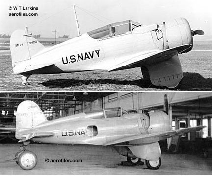
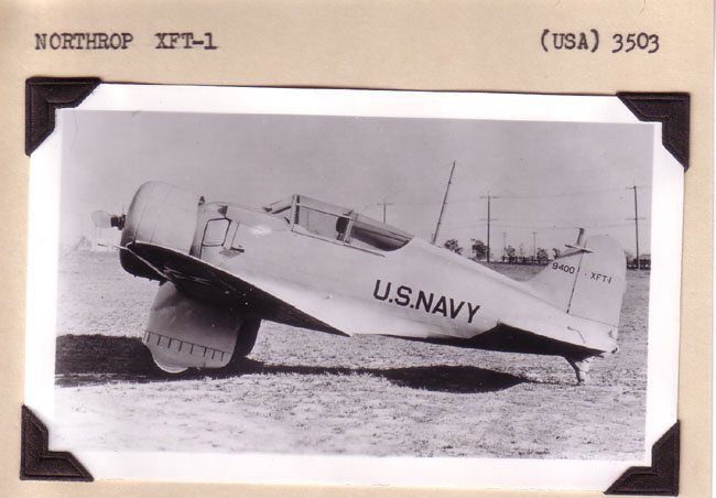
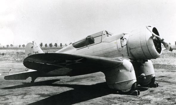
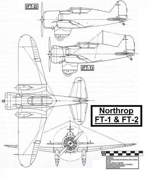
The new fighter was called XFT-1 and flew for the first time on January 16, 1934, powered by a 625 hp engine.
Compared to the Grumman, the Northrop fighter was twelve percent larger, two percent less heavy, eight kilometers per hour faster and considerably less maneuverable.
Both prototypes suffered from problems of longitudinal stability and tendency to spin, but the monoplane had a greater capacity for development using a retractable landing gear and more powerful engines.
Between March and August 1934, the XFT-1 was evaluated by the U.S. Navy showing poor control characteristics at low speeds.
The use of three flaps allowed the aircraft (with 177 sq. ft. of wing area) to fly at just 101 km/h during landing, while the Grumman biplane, (with 203 sq. ft. wing area) could land at 103 km/h without flaps.
The air trapped between the undercarriage spats and the central flap of the Northrop generated severe tail buffeting, making it difficult to control during the most dangerous stage of the flight.
In August 1934, the prototype was sent back to the manufacturer for modifications to improve controllability and forward visibility.
The aircraft was fitted with a new 650 hp. engine Wright XR-1510-8, new aerodynamic engine cowling designed by Wright, increase tailfin and revised landing gear spats. The radio mast and the telescopic gunsight were removed, and a new 120 U.S. gal fuel tank was installed.
After a second assessment in 1935, the Bu Aer still found the control unsuitable for carrier-board service.
The Wright engine was replaced by a heavier Pratt & Whitney R-1535-72 but rated at 700 hp.
Northrop felt the changes justified the new XFT-2 designation and, to compensate for the weight gain, it was reduced fuel capacity to only 80 U.S. gal, but the change only managed to worsen longitudinal instability.
After the third evaluation was performed between April and July 1936, the Navy announced that the XFT-2 was not airworthy, and the contract was closed out.
On July 21, the prototype crashed while being returned to Northrop.
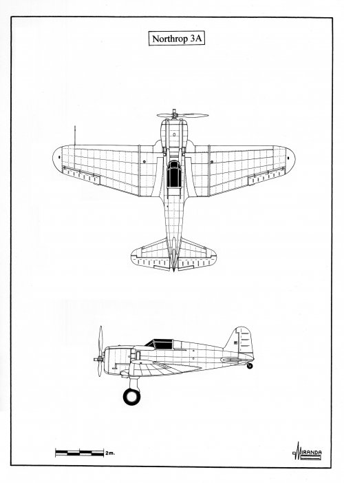
Northrop Gamma 3 (XFT-1) technical data
Wings: three-spar, multicellular, stressed skin construction in 24 ST Alclad, with flush riveting system, fillets, one piece center section and three slotted flaps.
Fuselage: All-metal, stressed skin semi-monocoque construction with large reinforcement rings and longitudinal stiffeners.
Tail surfaces: All-metal, cantilever construction with externally balanced controls.
Undercarriage: fixed, cantilever, with spatted main members.
Engine: one Wright XR-1510-26 air cooled radial engine rated at 625 hp, driving a two-bladed metal airscrew with adjustable pitch on the ground.
Proposed armament: two nose mounted 0.3-in machine guns.
Wingspan: 9.75 m, length: 6.68 m, height: 2,87 m, wing area: 16.44 sq. m, max weight: 1,704 kg, max speed: 378 km/h, landing speed: 101 km/h, service ceiling: 8,075 m, range: 1,570 km, rate of climb: 700 m/min.
Painting scheme: Aluminum overall with yellow wing upper surfaces, meatball insignias in four positions and black codes.
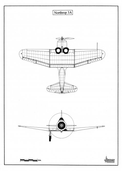
Northrop Gamma 3 (XFT-2) technical data
Wingspan: 9.75 m, length: 6.48 m, height: 2,87 m, wing area: 16.44 sq. m, max weight: 1,822 kg, max speed: 378 km/h, landing speed: 101 km/h, service ceiling: 8,075 m, range: 1,570 km, rate of climb: 700 m/min.
Engine: one Pratt & Whitney R-1535-72 air cooled radial engine rated at 700 hp, driving a two-bladed metal airscrew with adjustable pitch on the ground.
Armament: none.
Painting scheme: Aluminum overall with yellow wing upper surfaces, bright orange engine cowling, meatball insignias in four positions and black codes.
Czechoslovakia built the Avia B-534, Belgium the Fairey Firefly, Italy the Fiat CR.32, The Netherlands the Fokker D. XVII, France the Spad 510, England the Hawker Fury Mk. I, United States the Grumman F2F, Germany the Heinkel He 51, Japan the Kawanishi Ki.10 and the USSR the Polikarpov I-15.
But before the end of the decade, they were all obsolete, the culprit being a little-known British bomber called the Fairey Hendon, a monoplane capable of flying at 245 km/h in 1930.
In 1933 it was followed by the Martin B-10 (343 km/h) and the Boeing 247 (302 km/h), in 1934 the Douglas DC-2 (340 km/h), in 1935 the Douglas B-18 (348 km/h) and the Mitsubishi G3M (375 km/h) and in 1936 the Heinkel He 111 A-1 (402 km/h).
Faced with the new threat, the aircraft industry was forced to overcome existing prejudices against monoplane fighters that were still considered unsafe because of its dangerous high-speed landings, usually without flaps.
The lessons learned during dogfights in China and Spain showed that the time for change had come, but the use of the high-wing monoplane configuration on the Wibault 72, Gourdou 32, Nakajima Type 91, Morane 225, Loire 46, Dewoitine 27, Focke-Wulf 56 and P.Z.L. 7 models did not solve the problem because its excellent STOL characteristics did not compensate for the drag generated by the wing struts.
In 1932 the Hall-Springfield Bulldog and Gee Bee racing models developed in the United States showed that the most effective formula to reduce drag was the monoplane configuration with single leg landing gear and wheel spats.
In the mid-1930s, a design team from Fokker, under the direction of Erich Schatzki, concluded that it would not be effective to build a monoplane fighter with retractable undercarriage using the 600-700 hp engines available at that time.
Calculations indicated that disadvantages in increased weight and mechanical problems would not justify the three per cent increase in overall speed that would have been obtained by hiding the landing gear in the wings. In 1935 Fokker took the decision to build the D.XXI fighter, with fixed undercarriage streamlined to the greatest possible. During flight tests carried out in February 1936 with the FD-322 prototype, it was proven that the drag generated by the landing gear was only 10 per cent of the drag generated by the entire airframe.
The failure of the Vickers, Folland and Bristol British prototypes, fitted with retractable landing gear, tried to comply with the terms of the F5/34 specification, and the experiments carried out in Finland with a D.XXI equipped with retractable landing gear, confirmed Fokker's calculations.
On the other side of the world, Japanese engineer Jiro Horikoshi used the same formula during the construction of the Mitsubishi A5M, to meet the IJN specification 9-shi calling for a fast ground-based escort fighter.
Horikoshi used new technologies to achieve maximum performance with the limited power available:
-The thickness of wing was reduced to a minimum.
-The all-metal airframe skin was built using the flush riveting system patented by Northrop.
-The fixed landing gear, inspired by the Curtiss P-6E of 1932, was streamlined to the greatest extent.
Early in 1937 the new fighter quickly gained air superiority against Chinese Boeing 281 and Curtiss Hawk III fighters and flew escort missions for vulnerable G3M bombers equipped with belly fuel tanks.
But the Kaigun Koku Hombu still had serious doubts about the use of carrier-based monoplanes. At the time the 9-shi specification was prepared, only the French were operating monoplanes from the aircraft carrier Béarn, but they were aircraft with parasol-wing adapted of land-based models.
The monoplane fighter Nakajima Ki.27 had been operating in China since March 1938, and several units were captured and tested by Chinese and Soviets. Its performances were known in the West, but the archaic aspect of its airframe, with fixed undercarriage made the Allies think that it was a design technologically surpassed.
Ki.27 could evade the combat thanks to their greater speed, which even exceeded that of the Polikarpov I-16, fitted with retractable landing gear, despite the drag generated by the fixed undercarriage of the Japanese fighter.
On May 11, 1939, the Soviets were engaged in a war with Japan in the border of Outer Mongolia and Manchuria.
The Soviet Air Force (VVS) used Polikarpov I-152 biplane fighters that were especially vulnerable against the Ki.27.
In July the I-152 was hastily replaced by the new I-153 a biplane fitted with retractable undercarriage with 444 km/h top speed that just managed to survive the Japanese fury by using evasive manoeuvres.
Early in 1932, the U.S. Navy was concerned about the growing threat posed by the new fast bombers to aircraft carriers.
The industry responded with two projects of fast biplane fighters equipped with retractable landing gear.
In June, Grumman proposed a single-seat version of the FF-1 fitted with a Grover-Loening hydraulically operated landing gear, the prototype F2F was ordered in November 1932, reaching 369 km/h in October 1933.
Curtiss modified one F11C-2 fighter with a manually operated Dayton-Wright landing gear, the prototype XF11C-3 reached 352 km/h in May 1933.
Early in 1934, the U.S. Navy ordered twenty-seven Curtiss and fifty-four Grumman for operational evaluation.
In October, the F11C-3 entered service aboard the USS Ranger as BF2C-1 (362 km/h) but was withdrawn from carrier operations after barely a year due to landing gear malfunctions and structural resonance fatigue problems.
In January 1935 the Grumman F2F entered service but its maximum speed of 372 km/h was not considered sufficient to solve the problem that the Navy had been trying to solve for three years.
On December 6, 1932, the U.S. Navy Bureau of Aeronautics issued a specification calling for a carrier-based variant of the Boeing P-26 fitted with cantilever low-wing and flaps.
The answer was the XF7B-1, a monoplane equipped with enclosed cockpit and semi-retractable landing gear based on the Boeing Monomail.
One prototype was ordered in March 1933, reaching 375 km/h on September 14, but its 139 km/h landing speed was considered too high for carrier use.
On January 24, 1933, the Bu Aer issued the specification SD-204, calling for a carrier-based fighter based in the Northrop Gamma 2, with a landing speed equivalent to that of the biplane Grumman XF2F.
Northrop's design team, led by Ed Heinemann, proposed building a version of the Gamma 2E fast bomber, 68 per cent scaled down to adapt it to the dimensions of naval fighters and aircraft carrier elevators.
On May 8, 1933, Bu Aer ordered a single-seat low-wing monoplane prototype Northrop Gamma 3 (c/n 6, Bu No. 9400).
The new fighter was called XFT-1 and flew for the first time on January 16, 1934, powered by a 625 hp engine.
Compared to the Grumman, the Northrop fighter was twelve percent larger, two percent less heavy, eight kilometers per hour faster and considerably less maneuverable.
Both prototypes suffered from problems of longitudinal stability and tendency to spin, but the monoplane had a greater capacity for development using a retractable landing gear and more powerful engines.
Between March and August 1934, the XFT-1 was evaluated by the U.S. Navy showing poor control characteristics at low speeds.
The use of three flaps allowed the aircraft (with 177 sq. ft. of wing area) to fly at just 101 km/h during landing, while the Grumman biplane, (with 203 sq. ft. wing area) could land at 103 km/h without flaps.
The air trapped between the undercarriage spats and the central flap of the Northrop generated severe tail buffeting, making it difficult to control during the most dangerous stage of the flight.
In August 1934, the prototype was sent back to the manufacturer for modifications to improve controllability and forward visibility.
The aircraft was fitted with a new 650 hp. engine Wright XR-1510-8, new aerodynamic engine cowling designed by Wright, increase tailfin and revised landing gear spats. The radio mast and the telescopic gunsight were removed, and a new 120 U.S. gal fuel tank was installed.
After a second assessment in 1935, the Bu Aer still found the control unsuitable for carrier-board service.
The Wright engine was replaced by a heavier Pratt & Whitney R-1535-72 but rated at 700 hp.
Northrop felt the changes justified the new XFT-2 designation and, to compensate for the weight gain, it was reduced fuel capacity to only 80 U.S. gal, but the change only managed to worsen longitudinal instability.
After the third evaluation was performed between April and July 1936, the Navy announced that the XFT-2 was not airworthy, and the contract was closed out.
On July 21, the prototype crashed while being returned to Northrop.
Northrop Gamma 3 (XFT-1) technical data
Wings: three-spar, multicellular, stressed skin construction in 24 ST Alclad, with flush riveting system, fillets, one piece center section and three slotted flaps.
Fuselage: All-metal, stressed skin semi-monocoque construction with large reinforcement rings and longitudinal stiffeners.
Tail surfaces: All-metal, cantilever construction with externally balanced controls.
Undercarriage: fixed, cantilever, with spatted main members.
Engine: one Wright XR-1510-26 air cooled radial engine rated at 625 hp, driving a two-bladed metal airscrew with adjustable pitch on the ground.
Proposed armament: two nose mounted 0.3-in machine guns.
Wingspan: 9.75 m, length: 6.68 m, height: 2,87 m, wing area: 16.44 sq. m, max weight: 1,704 kg, max speed: 378 km/h, landing speed: 101 km/h, service ceiling: 8,075 m, range: 1,570 km, rate of climb: 700 m/min.
Painting scheme: Aluminum overall with yellow wing upper surfaces, meatball insignias in four positions and black codes.
Northrop Gamma 3 (XFT-2) technical data
Wingspan: 9.75 m, length: 6.48 m, height: 2,87 m, wing area: 16.44 sq. m, max weight: 1,822 kg, max speed: 378 km/h, landing speed: 101 km/h, service ceiling: 8,075 m, range: 1,570 km, rate of climb: 700 m/min.
Engine: one Pratt & Whitney R-1535-72 air cooled radial engine rated at 700 hp, driving a two-bladed metal airscrew with adjustable pitch on the ground.
Armament: none.
Painting scheme: Aluminum overall with yellow wing upper surfaces, bright orange engine cowling, meatball insignias in four positions and black codes.