- Joined
- 31 May 2009
- Messages
- 1,155
- Reaction score
- 793
Thank you Ghostmodeler for this useful and detailed history. Am I correct in believing that Northrop Grumman has the last, active in-house model shop among major aerospace manufacturers?

ghostmodeler said:There is a very good article in the 2006 Vol. 21, no. 4 issue of Code One magazine that covers Lockheed Martin's shop. The issue is accessible on-line at www.codeonemagazine.com.
 archive.aviationweek.com
 archive.aviationweek.com
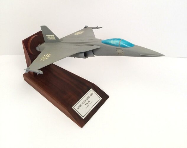
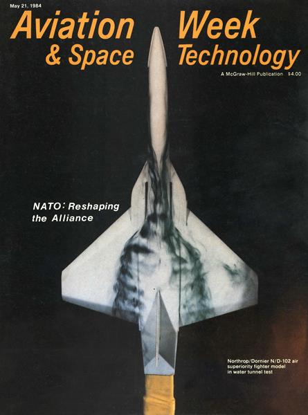
Grey Havoc said:Was the N/D-102 designation widely used at that time (1984)?
 archive.aviationweek.com
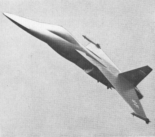
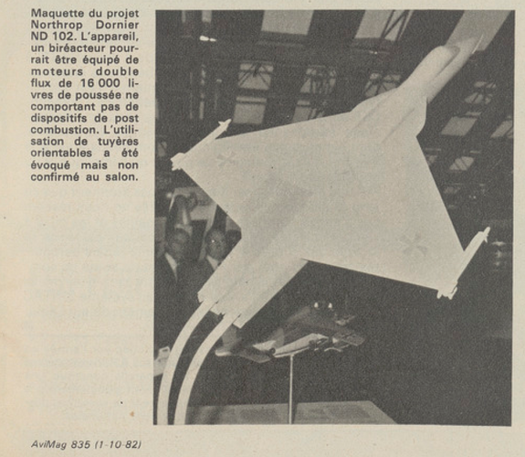
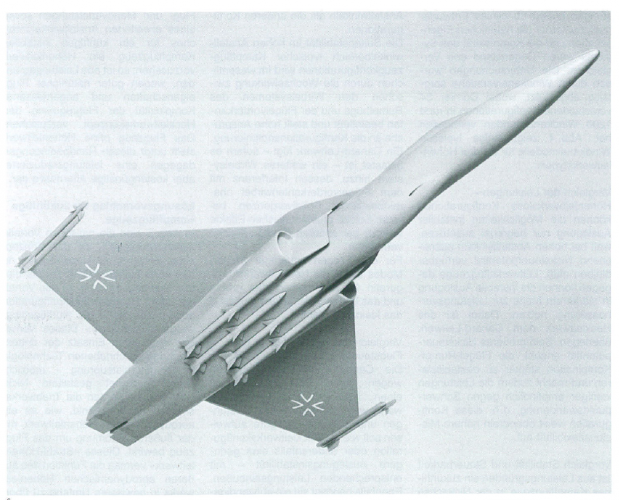
The 4 x Aim-120 ventral arrangement has always impressed me on the ND-102, and yet, it still has six under-wing hardpoints and two wingtip Sidewinder's!
The 4 x Aim-120 ventral arrangement has always impressed me on the ND-102, and yet, it still has six under-wing hardpoints and two wingtip Sidewinder's!
Although I'm still trying to assertain if it was to have a built-in cannon of some type??
Regards
Pioneer
 www.worthpoint.com
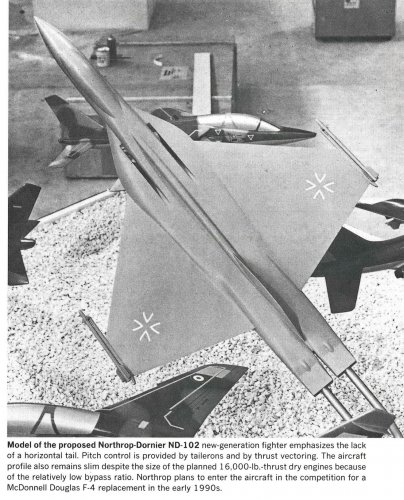
I'd be pretty sure primary pitch control would be from the elevons on the wing trailing edge. The thrust vectoring is then for increased authority at higher AoA. If the thrust vectoring fails then you recover to a narrower envelope to use the elevons.Its pitch authority was based on vectored thrust, wasn't it?
Actually, based on what I've read, the Northrop tailless designs used TV for their primary pitch control, which makes sense, since you can then use the elevons to maximize L/D during a turn/maneuvers. It also limited the amount of G's they could pull since it had to be used for both thrust and pitch. IIRC, they were usually good to around 7Gs. Having said that, I haven't any doubt the elevons would have the ability to take over picth control if the TV was disabled. As you noted, they would just be more alpha/pitch limited in such a scenario.I'd be pretty sure primary pitch control would be from the elevons on the wing trailing edge. The thrust vectoring is then for increased authority at higher AoA. If the thrust vectoring fails then you recover to a narrower envelope to use the elevons.
Quite possibly. Thinking about it, it would probably be an unstable design and so you need the higher rate elevons for fine trimming and could then use the lower rate TVC for gross trimming and gross pitch attitude changesActually, based on what I've read, the Northrop tailless designs used TV for their primary pitch control, which makes sense, since you can then use the elevons to maximize L/D during a turn/maneuvers.
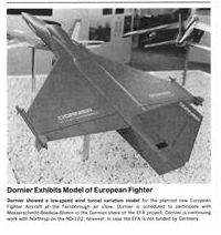
From Dornier Post 1983/2
Configuration Studies for Future Fighter Aircraft
In the 1990s, European air forces, particularly the German Air Force, planned the introduction of a new generation of tactical fighter aircraft for the air superiority role. Dornier has been conducting extensive concept studies and technology work related to this significant development project for several years. The following article describes which technologies are being prioritized for the aerodynamic design, how they can be applied in terms of performance requirements and cost-effectiveness, and how Dornier, together with Northrop, developed a promising configuration from the alternative solutions.
Commissioned by the German Federal Ministry of Defence and using its own resources, Dornier is developing a cost-effective overall concept for a future generation of fighter aircraft for the air superiority role. The key guiding principles for this ongoing concept work were already presented in the article "New Paths in Fighter Aircraft Construction" in issue 3/82 of our in-house magazine "Dornier Post" on pages 4-6.
A key objective of our work is to achieve maximum fleet combat power through a balanced relationship between the combat power of individual weapon systems and the procurable and operational size of the fleet. In this sense, previous investigations have allowed us to derive overarching requirements for the aerodynamic design parameters of future combat aircraft.
These are:
- Good and balanced performance across the entire flight envelope, tailored to the agility of the weapon system
- High operational flexibility, i.e., suitability for various missions and tactics in the subsonic, transonic, and supersonic ranges
- Short takeoff and landing distances
- Low radar signature.
To find a suitable configuration solution for this design objective, formulated here in general terms, Dornier first analyzed the cost-effectiveness of the technologies that contribute to the aerodynamic design. Then, through systematic investigation and evaluation of configurational solution alternatives, a preferred configuration was gradually narrowed down using these technologies in a targeted manner.
Key Technologies for Configuration Design
The following technologies have a decisive influence on the aerodynamic/flight-mechanical configuration: the wing concept as an optimal compromise between supersonic and transonic maneuverability performance, the shaping to reduce the radar signature, weapons integration, flight control, unstable design, and jet guidance. Three selected technologies will be discussed in more detail below:
Flight Control
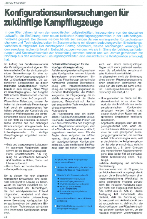
Flight control requires an electronic flight control system. It allows a controller to be inserted between the pilot and the aircraft's controls, to which a multitude of tasks (see Fig. 1) can be assigned. However, whether the controller is able to perform these tasks
depends heavily on the aerodynamic configuration itself. For example: An aircraft cannot be controlled at high angles of attack, even by a high-performance controller, if the necessary aerodynamic control effectiveness is lacking.
In general, the introduction of such a flight control system represents a considerable technical effort, which must be justified by the resulting performance improvements. This means:
- It is inappropriate, in terms of cost-effectiveness, to upgrade a design that could be improved by modifications to the aerodynamic configuration instead of using a controller with integrated intelligence.
- On the other hand, the effort involved in the control system can be appropriate if it results in inherent performance gains from a successful design that the pilot cannot demand because they are tied up with tactical tasks or physically unable to do so, for example, due to limitations of human reaction time. This is the case with the artificial stabilization of an aircraft.
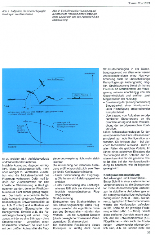
Unstable Design and Artificial Stabilization
Normally, an aircraft is designed to be stable in the pitch axis so that it returns to its initial flight attitude even after a disturbance in the angle of attack (vertical gust) without control inputs. With an unstable design, on the other hand, the aircraft immediately stalls without control input (see Fig. 2). A stable design, however, has the disadvantage that the allocation of the center of gravity and the center of lift must be made in such a way that ultimately the maneuvering flaps on the wing cannot be deployed optimally to achieve the maximum possible performance gains (i.e., loss of lift and increase in drag).
An unstable design, on the other hand, makes it possible to more or less avoid these performance disadvantages. Additionally, the pitch controllability of the aircraft is improved. However, this requires accepting the additional effort for artificial stabilization, because the pilot might not be able to react quickly enough manually. The necessary technical effort depends on the extent of the intended design instability (see Fig. 2 below) and also on the inherent characteristics of the configuration. For example, if the reaction speed of an aircraft, with which it amplifies a disturbance – without control correction – reaches a certain limit, it can no longer be stabilized, even with the greatest effort for flight stability control.
The application of the unstable design opens up two fundamentally different avenues for configuration:
- Performance gains can be achieved while maintaining the aircraft size.
- A smaller and ultimately more cost-effective aircraft can be built while maintaining the performance level.
Jet control
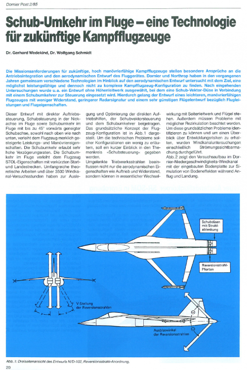
Integrating the jet engine into the control concept of an aircraft expands the actual function of the jet engine—namely, propulsion—to include steering (through movable nozzles) and deceleration (through jet reversal).
Thanks to new structural technologies in the nozzle assembly and, above all, a new propulsion technology without afterburning, the technical implementation of this concept will be cost-effective in the future, even for supersonic fighter jets. Thust vectoring offers a high potential for control forces and deceleration almost independent of speed and opens up two possibilities for use:
- Extending the (aerodynamic) controllability of a configuration while adding corresponding complexity.
- Transferring tasks from aerodynamic control elements to thrust vectoring, thus simplifying the aerodynamic configuration.
These key technologies for aerodynamic design can, in principle, be applied to any configuration. However, with the same technical effort, they do not provide the same advantages in all cases. In the sense of selectively using the technologies according to cost-effectiveness criteria for the entire fleet, this must be considered when choosing a configuration, as will be shown below.
Configuration Development
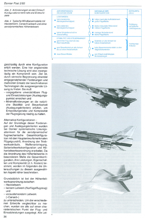
Requirements and Design Goals
The first step in a systematic approach is to translate the overarching design requirements into detailed requirements for the aerodynamic/flight-mechanical configuration (Fig. 3 - left). These lead to typical design features that the configuration would have to exhibit if it were to meet the respective requirement (Fig. 3 - center). Even this simple overview makes it clear that the design features (e.g., wing area) — and thus also the requirements — are contradictory to each other, i.e., they cannot all be fulfilled simultaneously by a single configuration. A technical solution sought here will therefore necessarily be a compromise. The goal is to find the most balanced solution by meaningfully limiting conflicting requirements and using the described technologies judiciously. It must achieve predefined essential flight and operational performance (design points) and meet minimum requirements for natural stability and controllability (design criteria) in order to keep development risk and complexity of the flight control system low.
Alternative Configurations — Based on these requirements and design criteria, Dornier developed systematic solution alternatives for the overall aerodynamic/flight-mechanical configuration with the main design features of wing planform, engine intake arrangement, weapons mounting, vertical stabilizer configuration, and horizontal stabilizer arrangement. Since the arrangement of the horizontal stabilizer significantly determines the overall configuration, its performance, characteristics, and complexity (i.e., costs), the investigations into this selected aspect are described in more detail below.
Basically, a distinction is made between the arrangement of the horizontal stabilizer:
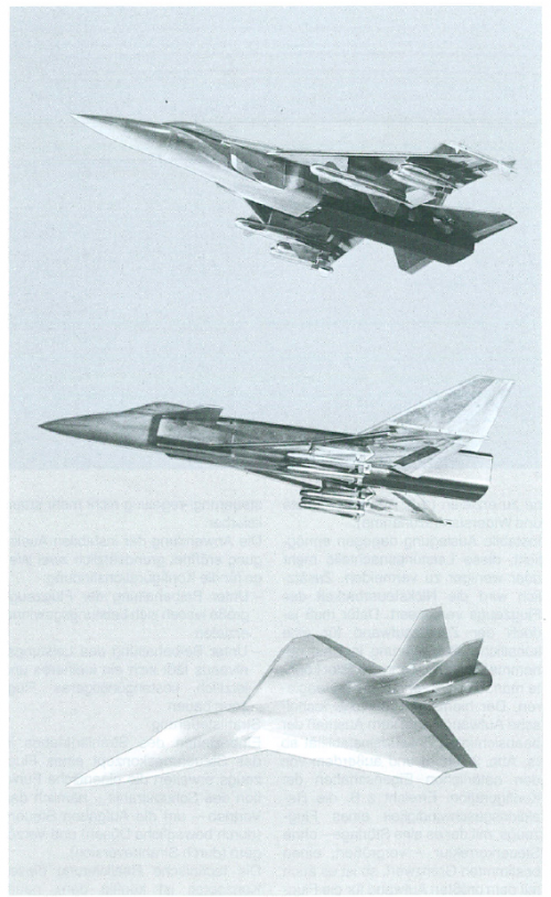
To make the various designs comparable, they were all designed for a characteristic point in flight and operational performance. All performance outside this design point, as well as the inherent characteristics and complexity of the system, were subject to comparison. The investigations were carefully supported by wind tunnel tests, with Dornier measuring 34 different configurations in approximately 1200 wind tunnel hours. Fig. 4 shows some typical wind tunnel models for the three horizontal stabilizer types.
- tail assembly
- no stabilizer (flying wing aircraft)
- a leading stabilizer (canard).
Comparison of Performance
Configurations without a horizontal stabilizer can only exploit the possibilities of an unstable design to a limited extent, because sufficient pitch control potential must remain available at high angles of attack. In contrast, aircraft with a tail assembly can utilize the unstable design to a greater degree for performance improvement. In this respect, the tail assembly is superior to the canard:
Its greater pitch control potential allows the wing-fuselage combination to be destabilized more effectively and also makes performance less sensitive to center of gravity shift, meaning this configuration also exhibits greater mission flexibility.
Comparison of Stability and Controllability
If a future fighter jet is designed to be unstable in the pitch axis for performance reasons, the canard configuration, unlike the other configurations, tends to become even more unstable with increasing angle of attack under load (pitch-up). As a result, its maximum instability can occur at angles of attack outside the range in which performance gains through instability are actually intended to be maximized. Furthermore, this canard configuration remains unstable up to higher angles of attack than the other configurations.
Lateral stability in the high angle-of-attack range of typical fighter jet configurations is primarily influenced by the interaction between the vortex systems of the nose and the wing leading edge and places high demands on configuration optimization.
A canard tail adds—if it is loaded—an additional vortex system, the interference of which with the leading-edge vortex causes characteristic roll divergences. Such problematic effects are avoided in other configurations.
For flying novel control modes, the canard configuration generally offers the greatest potential, and the canard-less aircraft the least.
Comparison of the effort required for flight control
The canard configuration requires greater stabilization effort due to its pitch-up tendencies if it is to exhibit approximately the same performance and stabilization quality as the canard configuration, or otherwise a lower design instability—with corresponding performance losses.
It also requires a more complex control system to achieve the same good lateral movement characteristics that the other configurations can naturally exhibit. This means a higher development risk for the canard configuration in comparison, and ultimately a more complicated and therefore more expensive flight control system for the same development result.
Conclusion: If a horizontal stabilizer is to be provided for a future unstable fighter aircraft to achieve outstanding flight and maneuverability performance as well as an extended angle-of-attack range, then for performance reasons, due to good natural flight characteristics, characteristics and appropriate complexity of flight control make the tail-tail concept preferable.
Under these conditions, the aircraft without a horizontal stabilizer represents a less powerful, but cost-effective alternative.
Proposed solution for future fighter aircraft
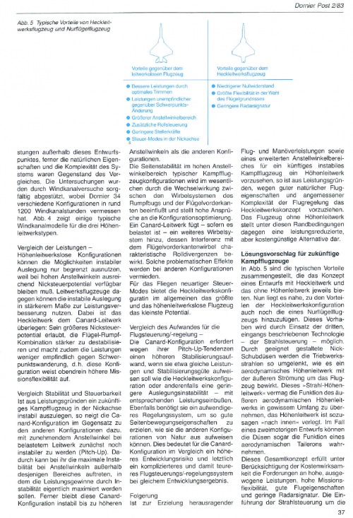
Figure 5 summarizes the typical advantages of the concept of a design with a tail and one without a horizontal stabilizer.
Tailed Aircraft Advantages
Tailless Aircraft Advantages
- Improved performance through optimal trimming
- Less sensitive performance to center of gravity changes
- Wider angle of attack range
- Additional roll control
- Reduced actuator forces
- Cut axis control modes
It is now natural to add the advantages of a flying wing aircraft to the advantages of the tail-tail configuration. This is made possible by the use of the third technology described at the beginning—jet control.
- Lower zero drag
- Greatest flexibility in wing planform selection
- Lower radar signal
By means of appropriately designed pitch-down thrust nozzles, the engine exhaust jets are deflected in the same way as an
aerodynamic horizontal stabilizer would be with the airflow around the aircraft. This "jet-equipped horizontal stabilizer" is able to take over the function of the outer aerodynamic horizontal stabilizer to a certain extent; the horizontal stabilizer is, so to speak, moved "inwards." In the case of a twin-engine design, the nozzles can even function as an aerodynamic taileron.
This overall concept, taking cost-effectiveness into account, fulfills the requirements for high, balanced performance, high mission flexibility, good flight characteristics, and a low radar signature. The introduction of jet control around the pitch axis also offers the advantage that, through appropriate design of the nozzle assembly, the integration of thrust reversal is made possible cost-effectively. This allows for effective deceleration in combat flight and the shortest possible landing roll distances.
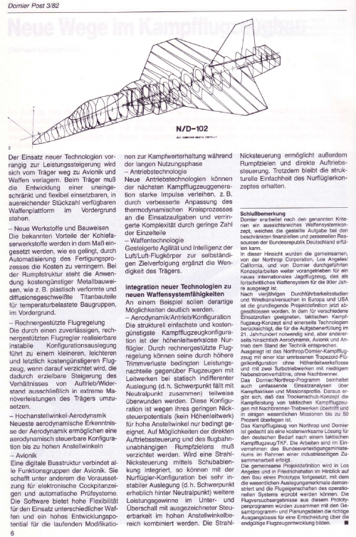
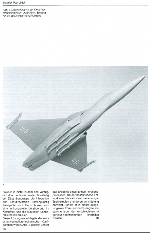
This proposed solution for the aerodynamic/flight-mechanical configuration is shown in Fig. 6 and is the result of a long iterative process. Since the described design incorporates a multitude of different technologies and their interrelationships, it could only be developed in this balanced form through close collaboration between the various engineering disciplines.
From Dornier Post 1982/3
On behalf of the Federal Minister of Defense and using its own funds, Dornier is developing a cost-effective overall concept for a future weapon system that can replace the F-4 Phantom as a tactical fighter aircraft in the German Air Force from the mid-1990s onward. The key guiding principles for this concept development are explained in the following article.
The Air Force of the Federal Republic of Germany is currently introducing the new Alpha Jet and Tornado weapon systems. They have significantly higher combat effectiveness than their predecessors, the G91 and F104. However, the Air Force must therefore accept a reduction in its fighter aircraft inventory. The Warsaw Pact, on the other hand, is constantly increasing the combat power of its fighter aircraft without reducing the size of its fleet.
The two new airborne weapon systems of the Air Force are primarily intended for engaging ground targets. In the 1990s, the Air Force will have a need for new air defense weapon systems. Since a sufficiently densely layered, comprehensive air defense system using surface-to-air missile systems does not appear feasible for cost reasons, the ground-based defense belt will continue to require the flexible component of a capable combat aircraft. Therefore, a new flying weapon system must replace the then-obsolete Phantom starting in the mid-1990s.
This need is countered by a rapidly narrowing gap between the rising costs of new flying weapon systems and the shrinking investment share of the defense budget. Other NATO countries face similar difficulties with comparable needs for a new combat aircraft. This situation forces clients and industry to adopt new, unconventional approaches to formulating military requirements, technology, and program policy.
Dornier is developing a cost-effective overall concept for the future weapon system on behalf of the
Federal Ministry of Defense (BMVg) and using its own resources.
Key guiding principles are:
Organization, management, and program design have a significant impact on program costs. The Franco-German Alpha Jet program has already demonstrated ways to achieve successful cost control.
- Maximum fleet combat power while considering the financial and personnel limitations of the Federal Republic of Germany
- New technologies for cost-effectiveness.
High Maximum Fleet Combat Power
The term fleet combat power encompasses the quality and quantity of a weapon system. With limited resources for development, procurement, and operation, a balanced relationship between the combat power of the individual weapon systems and the achievable and operational size of the fleet must be pursued.
In dialogue with the Federal Ministry of Defence, Dornier derives balanced design requirements from the military framework and proceeds in the following steps:
- Determining the impact of the requirements for aircraft, armament, and equipment on life-cycle costs
- Estimating the impact of the requirements on combat effectiveness under a given threat
- Identifying cost-effective exchange options instead of "classic" performance requirements
- Developing design requirements
- Reviewing the fleet combat power of the investigated solution alternatives.
Key aspects of the design requirements are:
- Effectiveness in close combat through a cost-effective combination of the weapon platform's maneuverability and the armament's increased agility
- High operational flexibility, i.e., suitability for very different missions and tactics in the subsonic and supersonic ranges
- Low vulnerability on the ground due to very short takeoff and landing roll distances.
New technologies for high cost-effectiveness
Under increasing cost pressure, two levels of deployment of new technologies for high cost-effectiveness (of the fleet) are available to the combat aircraft manufacturer:
- Selective deployment of new technologies in subsystems of the weapon system (e.g., structure, avionics, etc.)
- Integration of new technologies into new weapon system capabilities.
At the first level, some experimental experience already exists. The possibilities of the second level build on the new technologies, but envision an "interdisciplinary" linkage with an equally consistent focus on the criterion of cost-effectiveness.
Selective use of new technologies
Whereas in the past new technologies were used almost exclusively to increase performance—first of the carrier—then also of avionics and armament, with the well-known consequences of escalating costs, in the future, a selective deployment will take place according to criteria of cost-effectiveness for the entire fleet. The use of new technologies, primarily for performance enhancement, will shift away from the aircraft carrier towards avionics and weapons. For the aircraft carrier, the focus must be on developing a versatile and flexible weapons platform available in sufficient quantities.
New materials and construction methods The well-known advantages of carbon fiber materials will be utilized to the extent that costs can be reduced through automation of the manufacturing process. For the fuselage structure, the focus is on the application of cost-effective metal construction methods, such as plastically deformed and diffusion-welded titanium components for temperature-stressed assemblies.
Computer-aided flight control
The unstable configuration achievable through a reliable, computer-aided flight controller leads to a smaller, lighter, and ultimately more cost-effective aircraft, provided that the resulting increase in the lift-to-drag ratio is not solely translated into extreme maneuverability of the aircraft.
High-angle-of-attack aerodynamics
The latest aerodynamic insights enable an aerodynamically controllable configuration up to high angles of attack.
Avionics
A digital bus structure connects all functional groups of the avionics. Among other things, it creates the prerequisites for electronic cockpit displays and automatic testing systems. The software offers high flexibility for the use of different weapons and high development potential for ongoing modifications for maintaining combat effectiveness during the long service life
Propulsion Technology
New propulsion technologies can give the next generation of fighter aircraft a strong boost, e.g., through improved adaptation of the
thermodynamic cycle to operational tasks and reduced complexity through a smaller number of individual parts
Weapon Technology
Increased agility and intelligence of the air-to-air missiles for autonomous target tracking complements the maneuverability of the carrier. Integration of new technologies to new weapon system capabilities Such possibilities will be illustrated by an example.
Aerodynamics/Propulsion/Configuration
The structurally simplest and most cost-effective fighter aircraft configuration is the flying wing without a horizontal stabilizer. Computer-aided flight control can partially overcome its performance disadvantages compared to aircraft with tailplanes, which are caused by higher trim losses, when the aircraft has a statically neutral design (i.e., center of gravity coincides with the neutral point). This configuration is only conditionally suitable for high angles of attack due to its limited pitch control potential (no horizontal stabilizer). The possibilities of direct lift control and trajectory-independent fuselage aiming must be forgone. If a jet pitch control system is integrated via thrust deflection, further performance gains in subsonic and supersonic flight can be achieved with the flying wing configuration, even with a very unstable design (i.e., center of gravity significantly behind the neutral point), combined with excellent controllability in the high angle-of-attack range. The jet pitch control system also enables fuselage aiming and direct lift control. Despite this, the structural simplicity of the flying wing concept is maintained.
Concluding Remarks
According to the aforementioned criteria, Dornier is developing a promising weapon system concept that can fulfill the assigned task given the limited financial and personnel resources of the Federal Republic of Germany.
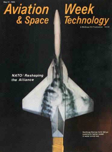
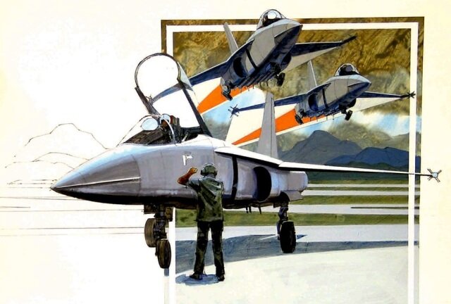
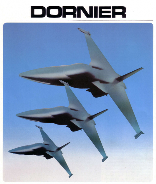
In this respect, the joint concept work conducted by Northrop Corporation, Los Angeles/California, and Dornier for a new international fighter aircraft, designed as an advanced weapon system for the 1990s, has been further advanced.
After four years of feasibility studies and wind tunnel tests in Europe and the USA, the fundamental project definition has now been completed. The tactical combat aircraft concept, suitable for various operational roles, incorporates technologies necessary for mission accomplishment in the 21st century while also representing the state of the art in terms of aerodynamics, avionics, and propulsion.
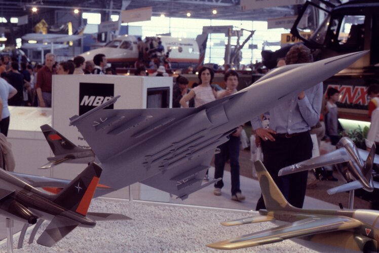
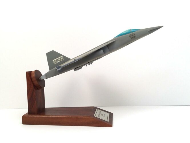
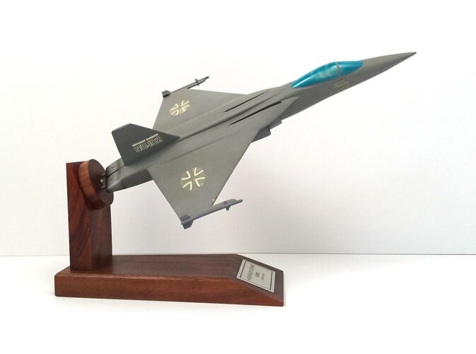
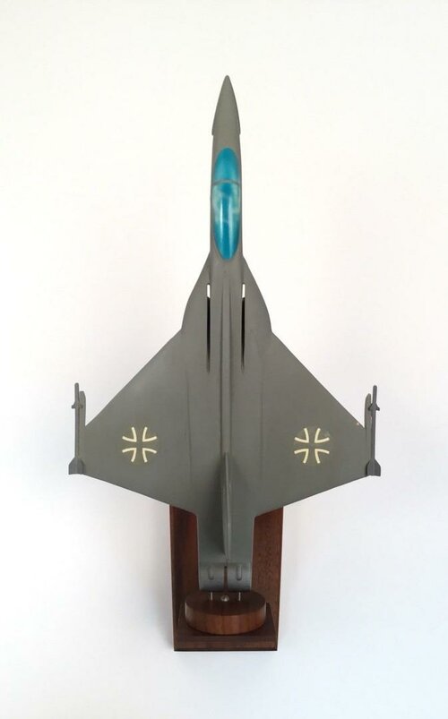
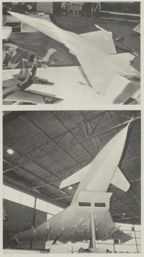
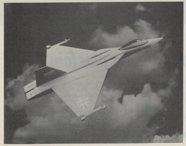
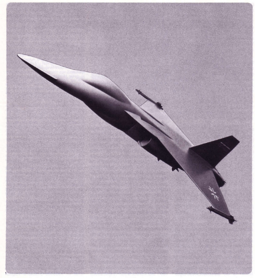
The Northrop/Dornier fighter aircraft is designed with a clearly defined trapezoidal wing configuration without a horizontal stabilizer and with two low-bypass turbojet engines, without afterburners.
The Dornier/Northrop program also includes comprehensive operational analyses of combat tactics and mission profiles. These analyses show that the dry-thrust concept surpasses the combat performance of tactical fighter aircraft with afterburner engines and is up to 50 percent superior in some key missions.
The Northrop and Dornier fighter aircraft is intended as a cost-effective solution for Germany's need for a tactical fighter aircraft. The work was carried out with the agreement of the Federal Ministry of Defense as part of an industry collaboration.
The joint project definition will continue in Los Angeles and Friedrichshafen with a view to the construction of a prototype with which the essential design features can be demonstrated and the flight characteristics of the operational system can be tested. The flight test results from this prototype program, together with the overall program and planning data, would form the right starting point for a decision on the final aircraft development.
Wehrtechnik - Volume 16 - Page 49The ND-102 is an F404 (Swedish version) with a so-called mini-burner, meaning an afterburner with a lower power increase and also lower fuel consumption. For available engines, this would be the best solution, however...
The EJ230 was projected to be around 16,000 dry, and the EJ270 around 17,500. They would have been later than the F119, but a better fit overall since scaling down the F119 might be an issue. And they would also capable of sustained supercruise since the EJ200 is.Yes. The long-term requirement was for 16000lb thrust per engine but this would need development of a new engine. Various engines were suggested including PW1120. Later on, they switched to F404 (RM-12) with partial reheat as the best near-term solution to get the required thrust.
Wehrtechnik - Volume 16 - Page 49
Long term, something like a scaled-down dry F119 would be ideal.
Everything is a trade off. Increasing dry thrust/weight ratio results in a relatively heavier propulsion system so the empty mass fraction increases. This then results in a lower available fuel and/or payload fraction, which may end up decreasing range/endurance overall.I am actually surprised no one has tried to put together a fighter with a dry thrust to weight of better than one, that would be an enormous advantage in combat endurance.