Blended Wing-Body Tested for F- 15 Concept used by North American Rockwell in its fighter design proposal to provide transonic speed regime maneuverability
By C. M. Plattner
Los Angeles
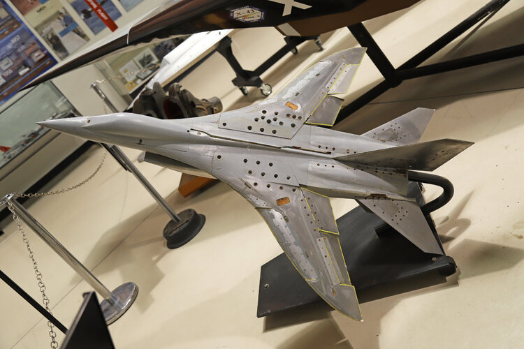
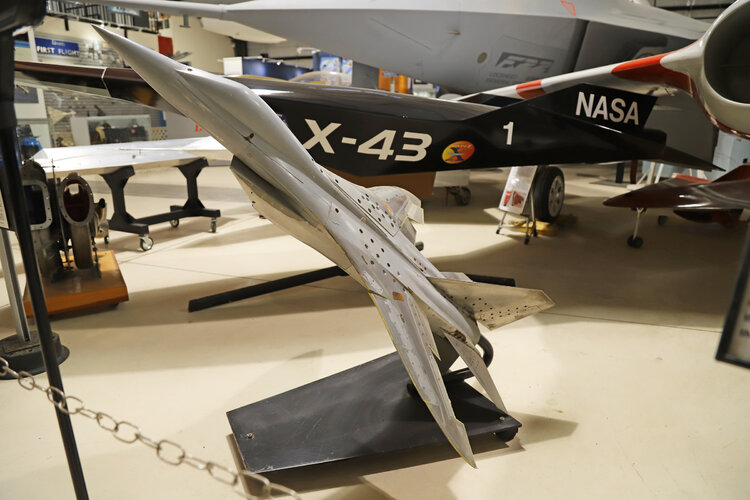
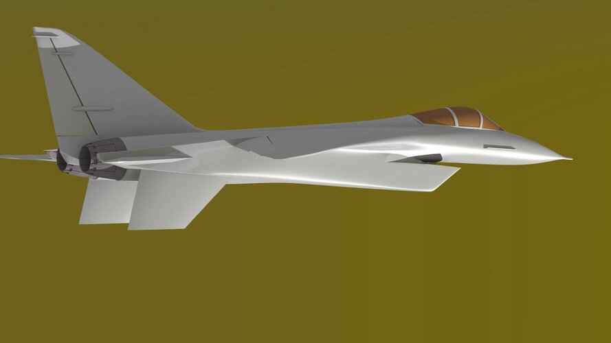
Blended wing—body concept featuring a highly-curved leading edge and a careful fairing of wing to fuselage has been incorporated in the North American Rockwell F-15 air superiority fighter design proposal. The concept. refined in more than 8.000 hr. of wind tunnel work, is aimed at providing a fixed-wing planform optimized for good maneuverability in the transonic speed regime.
North American Rockwell’s Los Angeles Div. first advanced the concept in Navy's F-14 fighter design competition in the fall of 1968. Following additional refinement and orientation to USAF requirements, the blended wing-body concept also was incorporated in the F-15 proposal (AW&ST Nov. 24. p.32). North American Rockwell is competing with McDonnell Douglas Corp. and Fairchild Hiller Corp. for the contract to build the Air Force F-15 air superiority fighter. A winner may be selected early next year.
Wind Tunnel Work
Wind tunnel and analytical work on aerodynamics of the blended wing—body concept began in-house in 1966 although the Air Force was pushing for a variable-sweep wing configuration for its FX fighter. It was not until early 1968, however, that North American Rockwell began serious configuration refinement.
The idea grew from work by the advanced study group at Los Angeles Div. It was attractive because it appeared as a means of developing a fixed-wing planform to do the FX job without the complexity and weight penalties associated with variable-sweep wings. The key challenge was validation of the theory and building confidence so that Navy and Air Force customers would find the approach credible.
The blended wing-body work begun in 1966 was separate from the funded North American FX study that year of a variable-sweep wing FX design. Later. in 1968, a second round FX study competition was held. but North American Rockwell lost to McDonnell Douglas and General Dynamics Corp. the two contractors selected. However. North American conducted an unfunded study for the Air Force using the same ground rules but incorporating the blended wing—body work into a fixed—wing configuration.
The company last year also participated in the Navy F-14 competition, submitting the only fixed-wing design. This competition ultimately was won by Grumman. The North American Rockwell F-14 participation was a serious attempt to win. company officials said, but the blended wing-body concept was not as fully verified as would have been necessary for a maverick proposal to win. even if other factors had been equal. the officials believed.
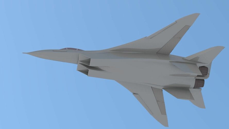
The blended wing—body planform defies simple description. North American Rockwell aerodynamicists said. although terminology such as a seimitar wing and ogee shape is sometimes used. The shape is remarkably similar to the transonic wing configuration which was invented by R. T. Whitcomb of the National Aeronautics and Space,Administration’s Langley Research Center (.twasr Feb. 17, p. 22).
North American won a contract as the sole bidder on a NASA Flight Research Center project to build a transonic wing for installation on an LTV F-8 for flight test. Work is under way on this project now.
Shape Similarity
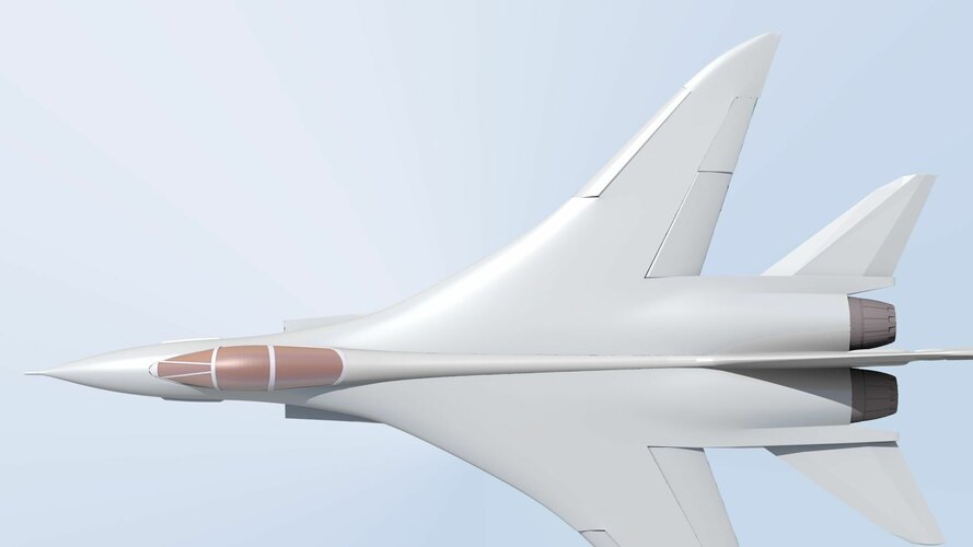
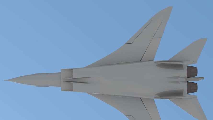
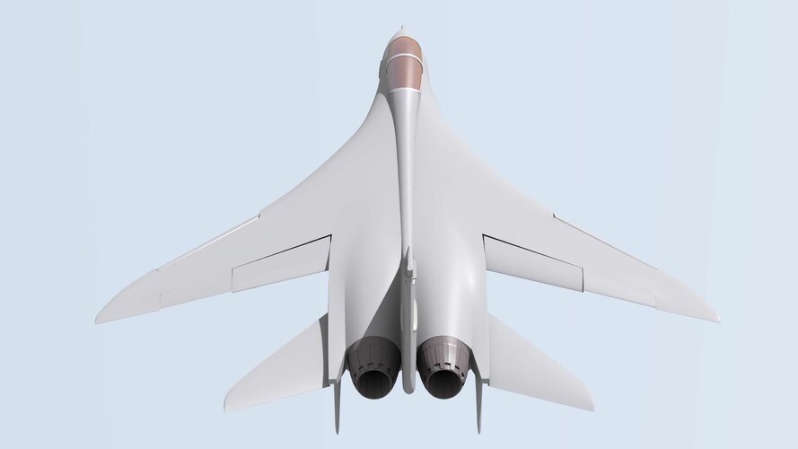
The reason for the similarity in shape is that the same suction theory was utilized to shape the leading edge. a North American Rockwell engineer said. The inboard portion is highly swept as it blends into the fuselage well forward. At about midspan. a point of inflection occurs and sweep angle is reduced. Near the tip. the leading edge begins to curve. increasing sharply in sweep angle to align with the local air stream. One of the considerations in translating a planform into hardware is the requirement for leading-edge flaps or slats. Ideally, a straight leading edge is desirable. but in the blended wingbody case. the need for leading-edge devices is minimized because of the ability to fly at high angles of attack.
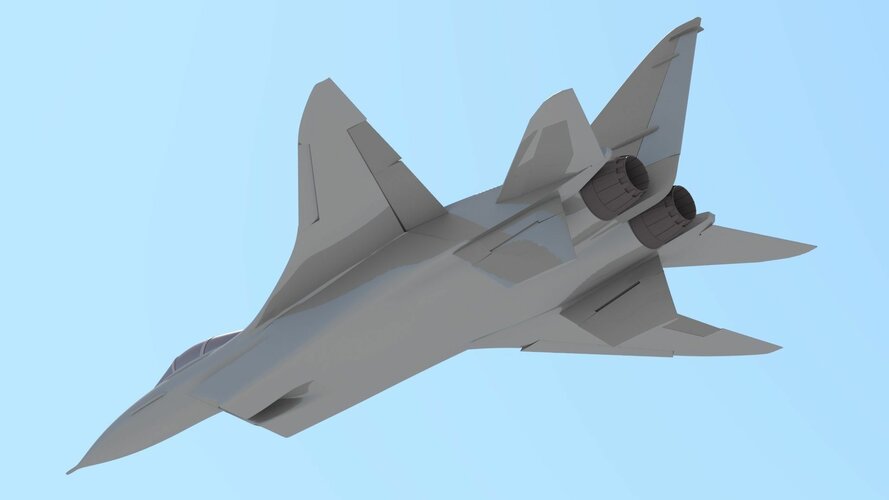
Trailing edge can be a straight line to simplify flap and aileron design because the blended wing»body concept is relatively insensitive to trailing-edge shape, an engineer said. Studies have indicated that moderate sweep angles are desirable at mid-span, and every effort is made to maintain attached airflow over the entire wing rather than have vortexes form. Because maximum speed is not a crucial design criteria. as was the case with the XB-70, for example, a moderate rather than a low aspect ratio is employed with blended wing-body fighter designs. Maximum speed of the F—15 air superiority fighter—in the Mach 2.5 region—is in part related to a decision to utilize an aluminum airframe.
Probably the key design criteria in turning the blended wing-body idea into a workable fighter design has been the emphasis on good maneuverability in the Mach 0.6-1.4 speed regime with a minimum of buffet. This. combined with a low wing-loading and high thrust-to-weight ratio provides the maneuverability needed in a superior dogfight aircraft, the company believes.
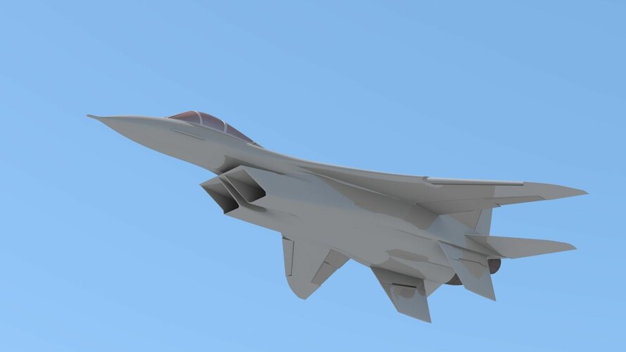
The shape of the leading edge has been set by finding the best solution to the two separate requirements of the subsonic and the supersonic flight regimes. For supersonic flight. the curvature is dictated largely by Whitcomb’s area-rule theory for the best cross—sectional distribution along the longitudinal axis to minimize wave drag. Subsonic leading-edge shaping is based on the principle of maintaining a uniform suction distribution spanwise to minimize drag due to lift. The goal is to obtain high buffet free lift coefficients for maximum angle of attack before onset of flow separation. The curvature applied inboard and outboard directly influences the suction distribution.
Shock Formation
Tip curvature also is important in the transonic region. according to S. F. Kwiatkowski of North American Rockwell. because the onset of shock formation at wing tips is delayed. thereby reducing drag due to lift and improving buffet characteristics. In contrast to straight swept wings. the scimitar leading edge becomes supersonic more gradually as speed increases. The second major geometry refinement. blending the wing into the body, serves the basic purpose of raising the proportion of lift supplied by the fuselage. In design. this is done by continuing the wing airfoil section to the fuselage centerline. then maintaining this curvature as much as possible during the subsequent refinement process of working canopy. inlets. weapons and the like into the configuration. The benefit of blending the wing to the body is twofold. Kwiatkowski said. It moves the wing center of pressure inboard because of the added lift generated by the fairing. This. in turn. produces slightly lower wing bending moments and is beneficial from the structural standpoint.
Chief Goal
Reduction of wave drag is the chief goal, however, of blending the forward wing into the fuselage. An additional benefit at supersonic speed is that the highly-swept inboard fairing produces more lift than at subsonic speed and thus reduces the rearward shift of aerodynamic center to help lower the trim drag. Many of the fundamentals in the blended wing-body concept are founded on work done by NASA and, to some degree, that by the British. A North American Rockwell engineer noted that leading-edge shaping was done as long ago as the early 1950s with the Vickers-Armstrongs, Ltd., Supermarine Swift. In the wind tunnel test work on the blended wing-body configuration, the principles entailed have held up well, engineers said.
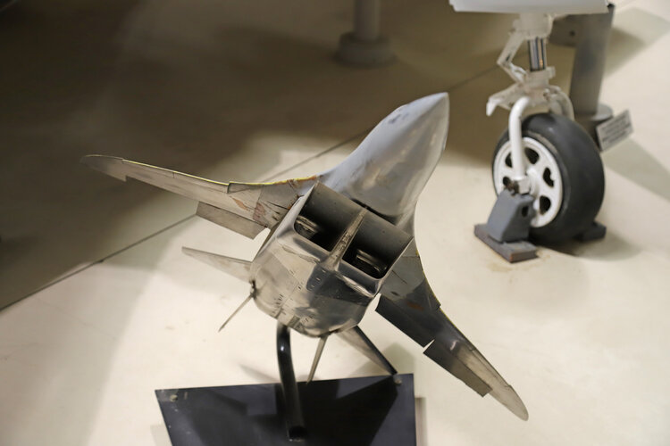
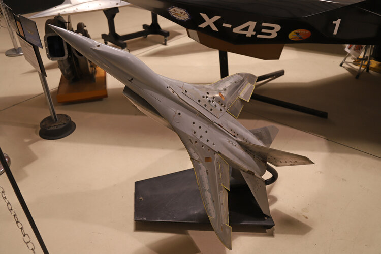
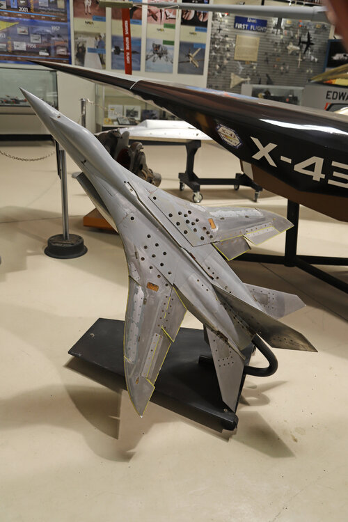
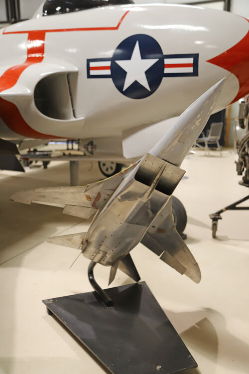
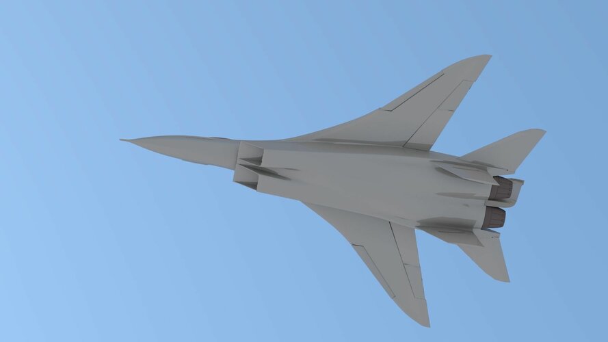
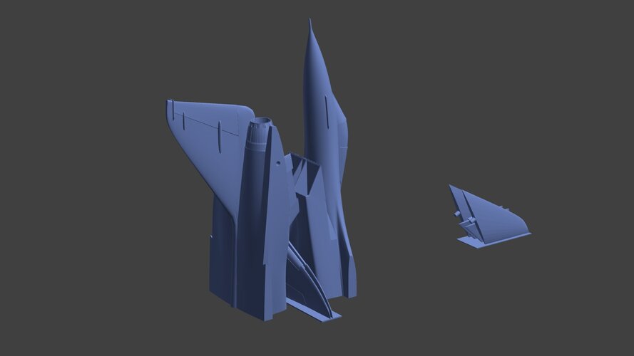
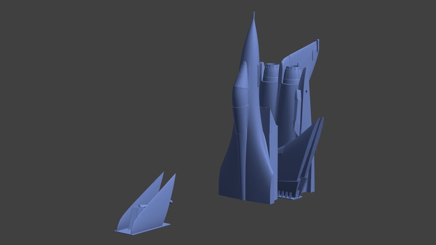
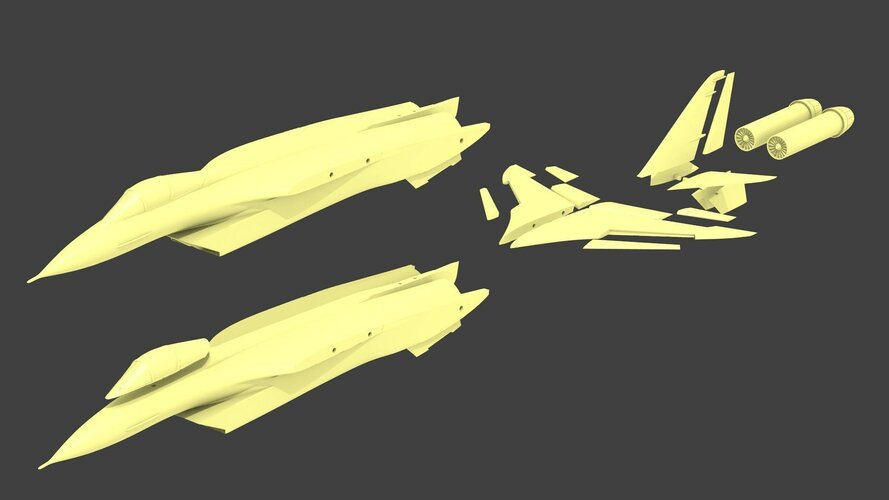
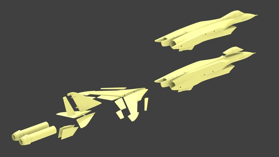
Photograph (p. 89) shows the last unclassified wind tunnel configuration prior to detailed refinement of the shape to military requirements. Some details, such as inlet and empennage shape, are believed to have changed, but the basic aerodynamic shape of the wing and fuselage remain the same. Camber and twist also are added in the final honing of the design and are not included in the photograph. North American Rockwell Los Angeles Div. refuses to discuss any specifics relative to its F-15 fighter design, but the 5.5-ft.-long wind tunnel model has been displayed at numerous public symposiums. It is believed to be a reasonably close likeness of the proposed F-15 in terms of wing and fuselage shape.
Basic Configuration
The same basic configuration was proposed to the Navy last fall, except that engines were moved inboard and a long common duct leading to a lower inlet under the nose was installed. The 5.5-ft. tunnel model is a force and moment model used for high-speed testing to obtain stability derivatives and performance parameters. It has aileron, flap and elevator segments, although they are not movable. Inlet design of the F-15 is believed to have changed in the direction of the F-14 design (AW&ST Dec. 16, 1968, p. 14) for the best efficiency and smoothest airflow to the engine.


")


.jpg")
