
You are using an out of date browser. It may not display this or other websites correctly.
You should upgrade or use an alternative browser.
You should upgrade or use an alternative browser.
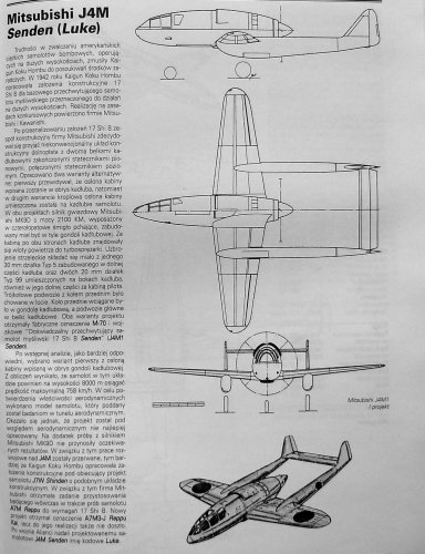
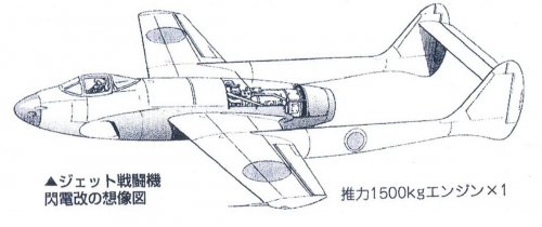
Mitsubishi J4M Senden ''Luke'' pusher fighter
- Thread starter Vietcong
- Start date
blackkite
Don't laugh, don't cry, don't even curse, but.....
- Joined
- 31 May 2007
- Messages
- 8,822
- Reaction score
- 7,730
Post-1 Mitsubishi J4M
Post-2 Mansyu Ki.98
Post-2 Mansyu Ki.98
Vietcong
Avation Enthusiast from VN
Justo,your drawing is look like the Mansyu Ki-98 than J4M except for the last drawing . does anyone have info or specs of the Jet Senden.
Boogey
B'Boomelang
- Joined
- 10 February 2009
- Messages
- 200
- Reaction score
- 42
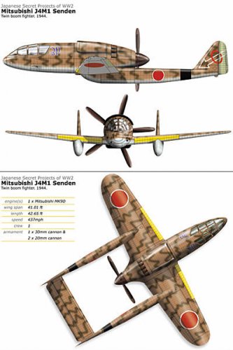
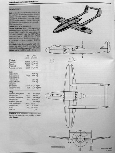
Project of the Mitsubishi J4M1 Senden was designed in two versions.
Sorry, I attach only photos of pages from my book " Japońskie Samoloty Marynarki " and a nice painting
of the Mansyu Ki-98.
Sorry, I attach only photos of pages from my book " Japońskie Samoloty Marynarki " and a nice painting
of the Mansyu Ki-98.
Attachments

blackkite
Don't laugh, don't cry, don't even curse, but.....
- Joined
- 31 May 2007
- Messages
- 8,822
- Reaction score
- 7,730
Attachments
- Joined
- 28 November 2006
- Messages
- 712
- Reaction score
- 739
Justo Miranda said:Mitsubishi A&B here
Am I correct that in Mitsubishi A&B-3.jpg drawing a jet-engined version may be seen (at the bottom of the drawing)?
Piotr
blackkite
Don't laugh, don't cry, don't even curse, but.....
- Joined
- 31 May 2007
- Messages
- 8,822
- Reaction score
- 7,730
Next. Enjoy.
Another one is Manshu(満州飛行機) Ki-98 high altitude fghter.
Please enjoy previous page,too. ;D
Another one is Manshu(満州飛行機) Ki-98 high altitude fghter.
Please enjoy previous page,too. ;D
Attachments

blackkite
Don't laugh, don't cry, don't even curse, but.....
- Joined
- 31 May 2007
- Messages
- 8,822
- Reaction score
- 7,730
Stargazer2006 said:Fantastic! The second part of the set are plastic models, right?
Yes it is.
http://www.geocities.jp/rxp05513/jyo-kyo001_148.htm

- Joined
- 11 March 2006
- Messages
- 8,629
- Reaction score
- 3,840
For comparison with the Borovkov-Florov Aircraft "D", posted by Stargazer, please see
http://www.secretprojects.co.uk/forum/index.php/topic,15086.msg151049.html#new
http://www.secretprojects.co.uk/forum/index.php/topic,15086.msg151049.html#new
blackkite
Don't laugh, don't cry, don't even curse, but.....
- Joined
- 31 May 2007
- Messages
- 8,822
- Reaction score
- 7,730
Hi!
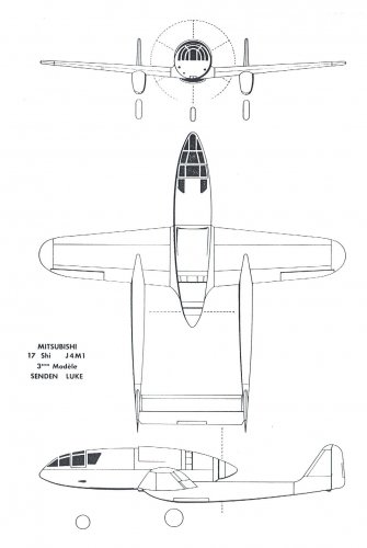
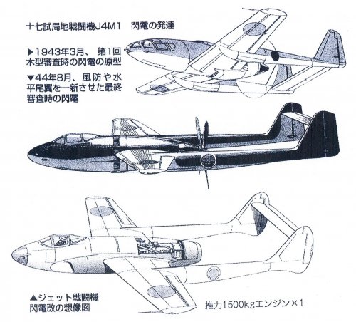
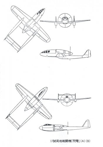
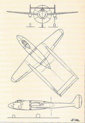
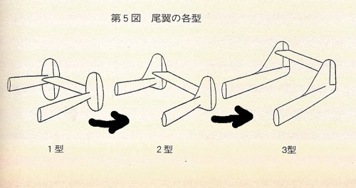
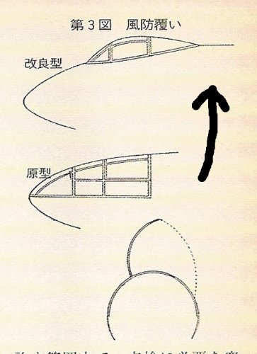
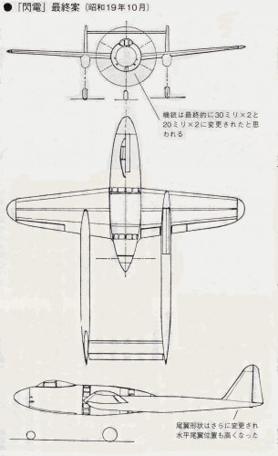
Senden early design and final design. Please watch vertical tail stabilizer shape.
Source : Unknown militaly aircraft development Vol(2/2), Aireview magazine special edition, 1999, ISBN4-87357-051-4
and internet.
Senden early design and final design. Please watch vertical tail stabilizer shape.
Source : Unknown militaly aircraft development Vol(2/2), Aireview magazine special edition, 1999, ISBN4-87357-051-4
and internet.
Attachments
blackkite
Don't laugh, don't cry, don't even curse, but.....
- Joined
- 31 May 2007
- Messages
- 8,822
- Reaction score
- 7,730
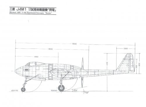
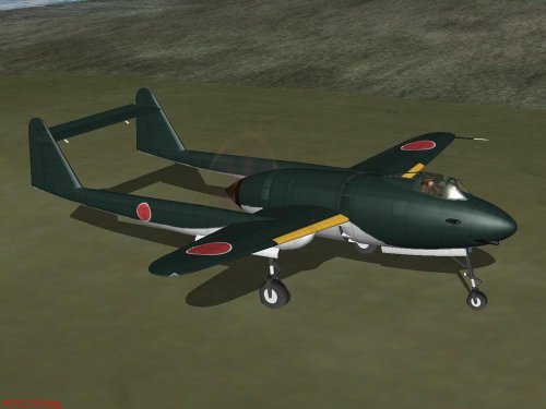
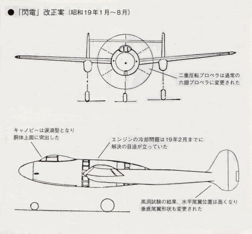
The first mockup inspection for Senden by the IJN was held in March 1943, after inspection, the IJN ordered Mitsubishi to change wind shield design from fast back shape to bubble shape to get better view from the cockpit.
Attachments

blackkite
Don't laugh, don't cry, don't even curse, but.....
- Joined
- 31 May 2007
- Messages
- 8,822
- Reaction score
- 7,730
Hi!
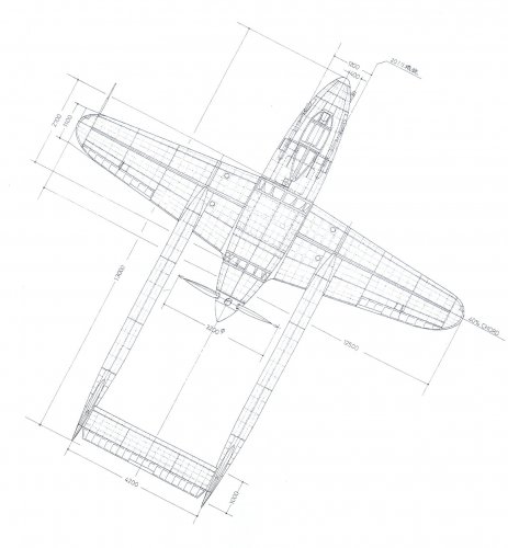
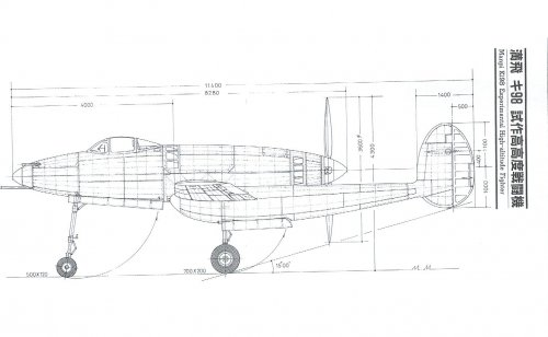
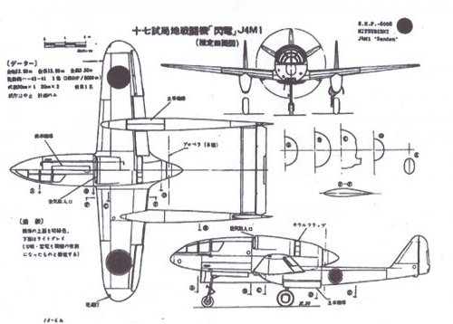
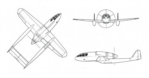
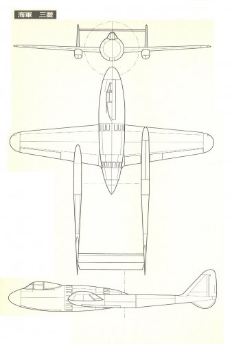
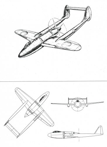
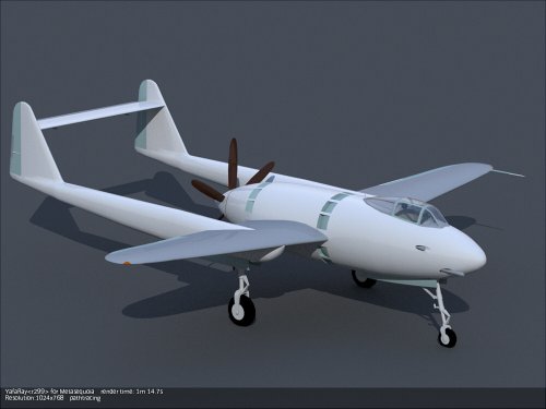
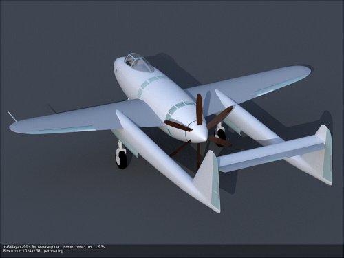
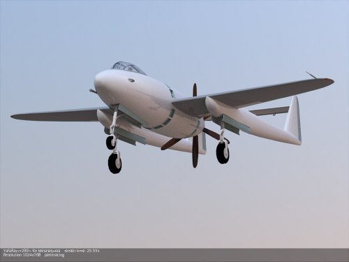
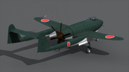
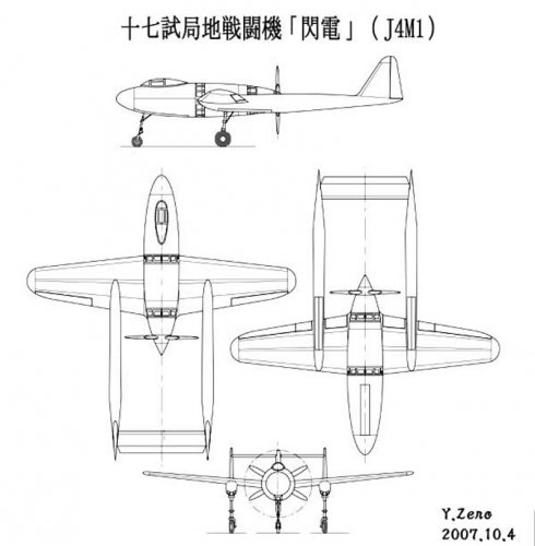
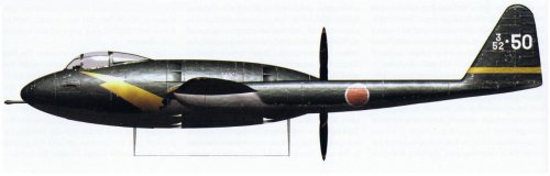
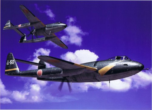
Very precise line and color Senden 3-side view drawings.
http://alternathistory.org.ua/proekt-vysotnogo-istrebitelya-mitsubishi-j4m-senden-j4m-yaponiya
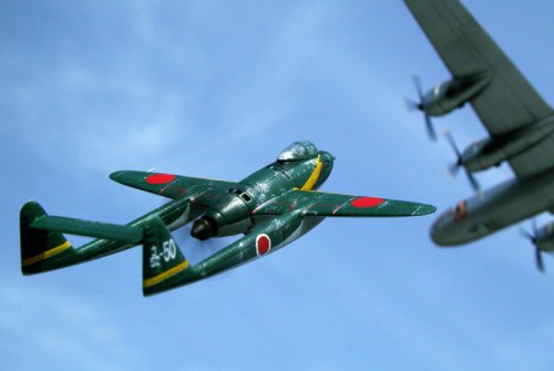
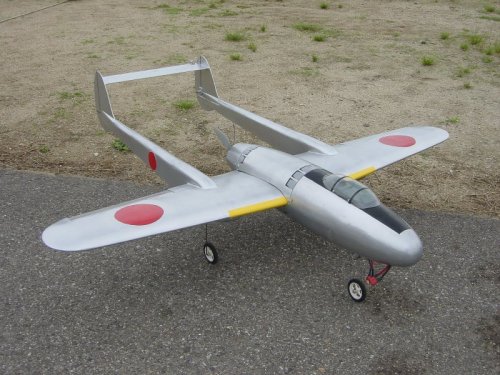
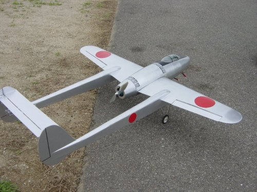
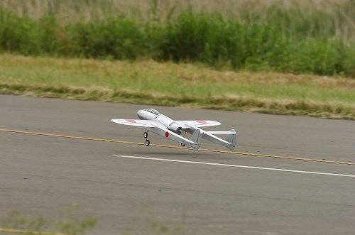
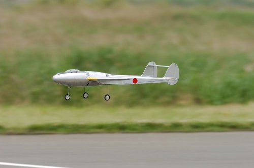
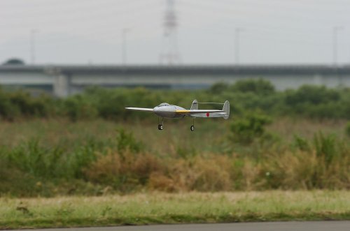
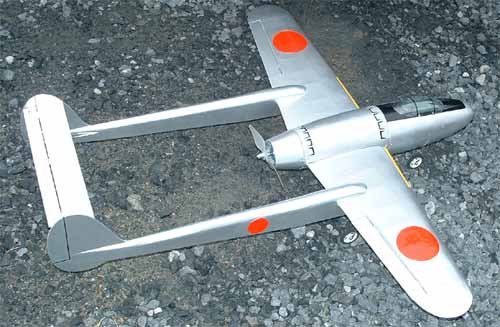
And Senden RC model.(Electric motor)
Very precise line and color Senden 3-side view drawings.
http://alternathistory.org.ua/proekt-vysotnogo-istrebitelya-mitsubishi-j4m-senden-j4m-yaponiya
And Senden RC model.(Electric motor)
Attachments
blackkite
Don't laugh, don't cry, don't even curse, but.....
- Joined
- 31 May 2007
- Messages
- 8,822
- Reaction score
- 7,730
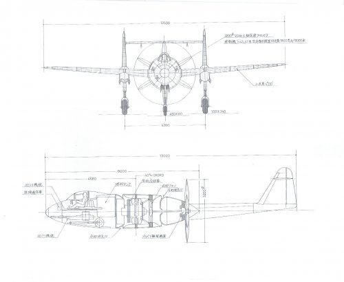
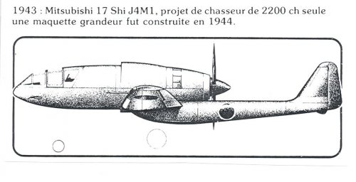
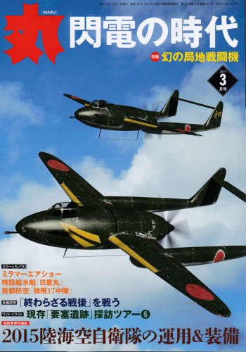
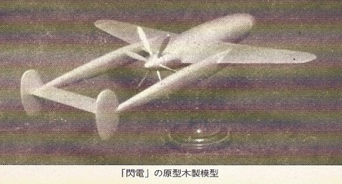
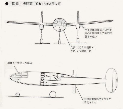
Senden initial plan with 3 blades contra rotating propeller. (Before March 1943)
Source : Maru magazine March 2015
This shape is different from the initial Senden shape which we have been seen. (The third picture, I think that it's a Senden another plan)
This shape is same as Mitsubishi wooden model.(Second picture)
Source : Maru magazine March 2015
This shape is different from the initial Senden shape which we have been seen. (The third picture, I think that it's a Senden another plan)
This shape is same as Mitsubishi wooden model.(Second picture)
Attachments

blackkite
Don't laugh, don't cry, don't even curse, but.....
- Joined
- 31 May 2007
- Messages
- 8,822
- Reaction score
- 7,730
Gildasd
Space fantasist
Are there any studies or tests on how this kind of aircraft performed, especially how they reacted to compressibility?
blackkite
Don't laugh, don't cry, don't even curse, but.....
- Joined
- 31 May 2007
- Messages
- 8,822
- Reaction score
- 7,730
I can't find any answer about your question in this Maru magazine.Gildasd said:Are there any studies or tests on how this kind of aircraft performed, especially how they reacted to compressibility?
I only find these equivalent sectional area.
Type 96 carrier fighter : 0.45 (square meter)
Zero fighter type 52 : 0.23
Suisei carrier dive bomber : 0.17
Raiden interceptor : 0.21
Shiden fighter : 0.23
Reppu : 0.17
Shiden-kai : 0.17
Senden : 0.12 (calculated value)
blackkite
Don't laugh, don't cry, don't even curse, but.....
- Joined
- 31 May 2007
- Messages
- 8,822
- Reaction score
- 7,730
Senden
Span : 12.5m, Length : 13m, Height : 3.5m, Wing area : 22 square meter, Gross weight : 4400kg
Senden another plan
Span : 12.5m, Length : 12.5m, Height : no data, Wing area : 24.7 square meter, Gross weight : 4886kg
Chief designer Eitaro Sano said that
(1)Senden engine cooling system was successfully established in February 1944.
(2)Hard vibration of tail horizontal stabilizer was also disappeared by design change.
(3)But the development of Mitsubishi MK9D engine with valcan coupling was not easy, the highest level member of the IJN and Mitsubishi lost interest for Senden.
Eitaro Sano designed F1M2 observation plane.
http://www.pacificwrecks.com/reviews/famous_airplanes_f1m2.html
The design group of Mitsubishi was very busy with improvement of Raiden, zero and development of a Reppu.
Design team of senden which had trouble on its hands variously fell the painful situation gradually.
Attachments
blackkite
Don't laugh, don't cry, don't even curse, but.....
- Joined
- 31 May 2007
- Messages
- 8,822
- Reaction score
- 7,730
Hi!
Source : internet
Source : internet
Attachments

blackkite
Don't laugh, don't cry, don't even curse, but.....
- Joined
- 31 May 2007
- Messages
- 8,822
- Reaction score
- 7,730
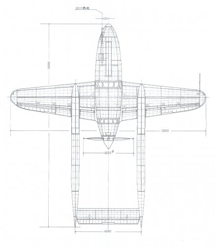
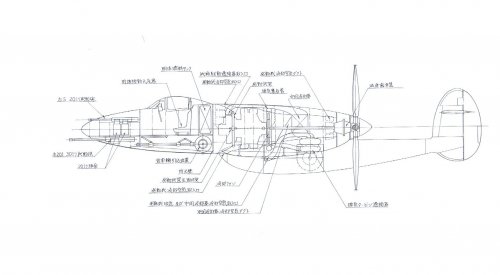
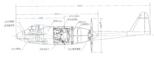
I tried to install Shinden HA43-42(MK9D) engine to Senden drawing. But very difficult especially to think about ram air intake concept for Vulkan coupling drive first stage supercharger.
Senden is very hard to understand. It's a big mystery.
For me the best solution is to have ram air intake at outside of the fuselage, but existing Senden model picture did not have such a air intake.
Oil cooler position is also mystery for me. Is it located surrounding outside of the engine?
Am I making some big misunderstandings?
Attachments
Last edited:
blackkite
Don't laugh, don't cry, don't even curse, but.....
- Joined
- 31 May 2007
- Messages
- 8,822
- Reaction score
- 7,730
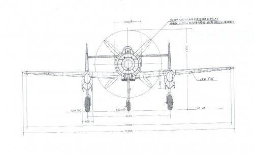
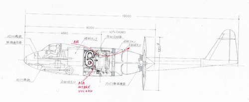
Thanks a lot brilliant Justo-san.
Bottom air intake is for Vulkan coupling drive supercharger and engine coling.
Bottom air intake and Vulkan coupling drive supercharger were connected by ram air duct. Excellent solution!!
How do you think about oil cooler position? Were there some space between engine and fuselage outer skin for oil cooler?
Last edited:
blackkite
Don't laugh, don't cry, don't even curse, but.....
- Joined
- 31 May 2007
- Messages
- 8,822
- Reaction score
- 7,730
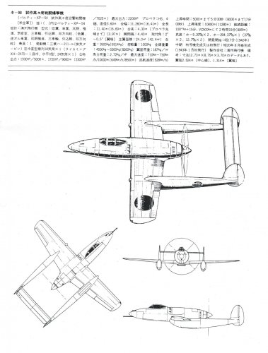
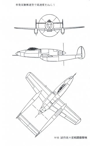
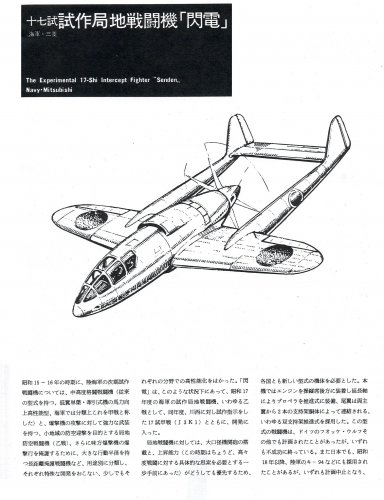
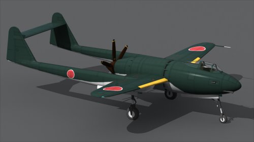
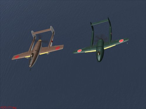
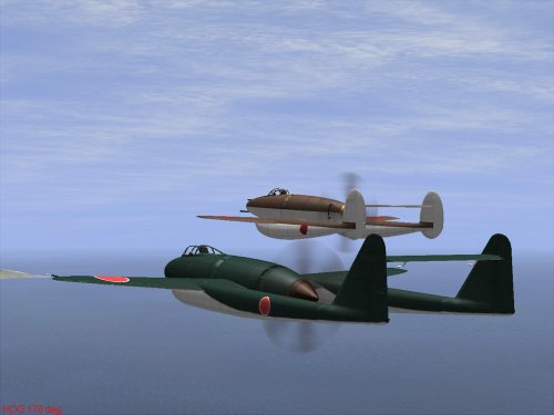
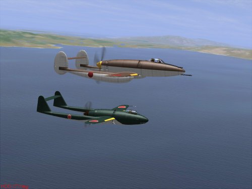
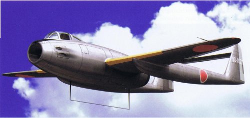
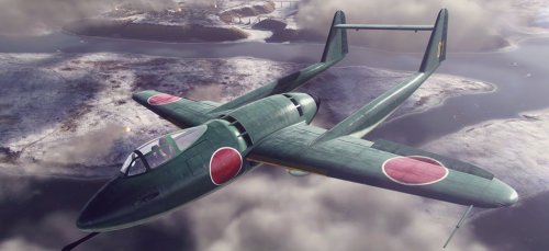
Senden’s span was 12.5 m, total length was 13 m, the main wing area was 22 m2 and the total weight was 4-4 tons.
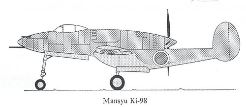
Senden’s size was slightly larger compared with Manshu Ki-98, and the total weight was almost same.
The wing area of Senden was 2m2 smaller that Ki-98.
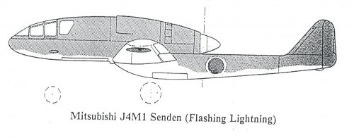
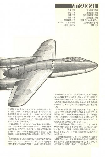
The engine was the Mitsubishi "Ha 43" 41 type, and because of the almost same engine system as the Ki 98, the overall shape became similar.
But Senden had middle wing and the fuselage which support the horizontal tail stabilizer was slightly long.
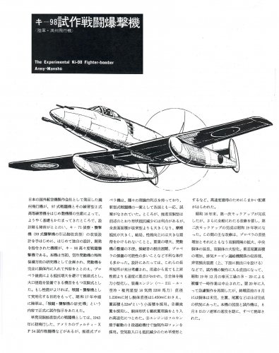
The problem was in the engine, as all of the other Japanese prototypes were.
According to "Zero Fighter" by Jiro Horikoshi , co-authored Masatake Okumiya ,
"In the spring of 1944, when we made the fuselage for the engine experiment and carried out the operation test with a prototype engine, the engine cylinder temperature distribution was good, and it was a prospect of practical use if limited to engine cooling".
However, the element that the performance decrease was repeatedly increase every time at the operation test, and the Vulkan coupling to drive supercharger did not work well, and the outlook was not bright at all.
Moreover, unfortunately, because it was found that there was a possibility of vibration of the tail stabilizer by the propeller flow in the wind tunnel test, position change of the horizontal tail stabilizer was needed, the progress with a design wasn't desirable.
Technical difficulties were expected because Senden was an inexperienced special type aircraft.
Mitsubishi actively received orders for Senden, chief designer Eitaro Sano and engineers worked on the development with great enthusiasm, but most of the people in the company hesitated to focus on Senden. Under these circumstances, the company's upper management's willingness to Senden gradually faded.
Therefore, the engineers in charge of Senden were put in a painful position.
After that, in October 1944, prototype models were consolidated for the unification of the prototype model reduction, and the Senden was truncated.
Compared to the Ki 98, which continued to work until just before the completion of the prototype, the Senden engineers in charge were unlucky.
Senden’s size was slightly larger compared with Manshu Ki-98, and the total weight was almost same.
The wing area of Senden was 2m2 smaller that Ki-98.
The engine was the Mitsubishi "Ha 43" 41 type, and because of the almost same engine system as the Ki 98, the overall shape became similar.
But Senden had middle wing and the fuselage which support the horizontal tail stabilizer was slightly long.
The problem was in the engine, as all of the other Japanese prototypes were.
According to "Zero Fighter" by Jiro Horikoshi , co-authored Masatake Okumiya ,
"In the spring of 1944, when we made the fuselage for the engine experiment and carried out the operation test with a prototype engine, the engine cylinder temperature distribution was good, and it was a prospect of practical use if limited to engine cooling".
However, the element that the performance decrease was repeatedly increase every time at the operation test, and the Vulkan coupling to drive supercharger did not work well, and the outlook was not bright at all.
Moreover, unfortunately, because it was found that there was a possibility of vibration of the tail stabilizer by the propeller flow in the wind tunnel test, position change of the horizontal tail stabilizer was needed, the progress with a design wasn't desirable.
Technical difficulties were expected because Senden was an inexperienced special type aircraft.
Mitsubishi actively received orders for Senden, chief designer Eitaro Sano and engineers worked on the development with great enthusiasm, but most of the people in the company hesitated to focus on Senden. Under these circumstances, the company's upper management's willingness to Senden gradually faded.
Therefore, the engineers in charge of Senden were put in a painful position.
After that, in October 1944, prototype models were consolidated for the unification of the prototype model reduction, and the Senden was truncated.
Compared to the Ki 98, which continued to work until just before the completion of the prototype, the Senden engineers in charge were unlucky.
blackkite
Don't laugh, don't cry, don't even curse, but.....
- Joined
- 31 May 2007
- Messages
- 8,822
- Reaction score
- 7,730
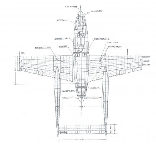
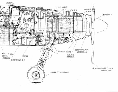
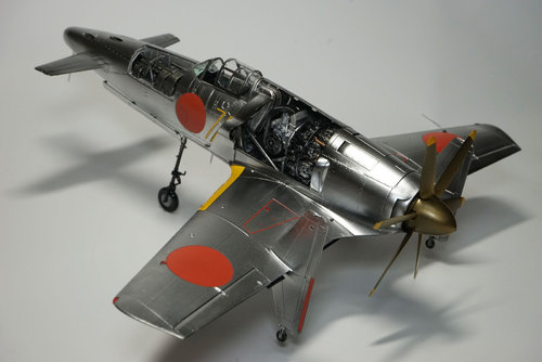
If Senden engine exhaust gas nozzles were designed properly, it might act as the ejector to induce oil cooler cooling air same as Shinden.
Shinden's engine had 18 exhaust nozzles.
4 nozzles exhaust gas were used for thrust.(Located upper part of the engine.)
8 nozzles exhaust gas were used for ejector(jet pump) which take oil cooler cooling air. (Located middle part of the engine.)
6 nozzles exhaust gas were used for ejector which exhaust engine room hot air.(Located bottom part of the engine.)
Of course engine was cooled by mainly forced cooling air by forced cooling fan which located behind the engine.
You can see oil cooler air intake in the first and the third picture.(After end of the fuselage)
Attachments
Last edited:
windswords
ACCESS: Secret
- Joined
- 19 May 2009
- Messages
- 389
- Reaction score
- 219
Shinden's engine had 18 exhaust nozzles.
4 nozzles exhaust gas were used for thrust.(Located upper part of the engine.)
8 nozzles exhaust gas were used for ejector(jet pump) which take oil cooler cooling air. (Located middle part of the engine.)
6 nozzles exhaust gas were used for ejector which exhaust engine room hot air.(Located bottom part of the engine.)
This might be a better picture for ;your explanation of the Shinden's exhaust nozzles
 :
:blackkite
Don't laugh, don't cry, don't even curse, but.....
- Joined
- 31 May 2007
- Messages
- 8,822
- Reaction score
- 7,730
Thanks a lot windswords-san!
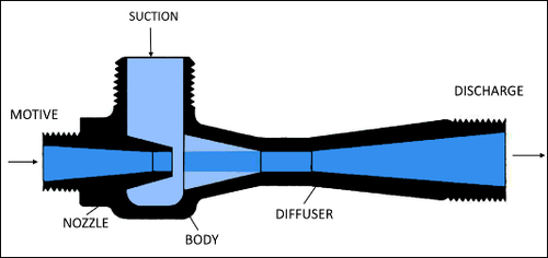
Oil cooler was located suction side. It's better to have air intake, ejector and oil cooler position in the windwords-san's drawing.
Of course oil cooler was located front of the ejector, left side of the exhaust nozzle aft end which is seen in the windwords-san's contribution.
And there was a air intake front of the oil cooler. https://www.secretprojects.co.uk/attachments/20161017_sinden_01-jpg.620546/
 www.hanwel.com
Oil cooler was located suction side. It's better to have air intake, ejector and oil cooler position in the windwords-san's drawing.
Of course oil cooler was located front of the ejector, left side of the exhaust nozzle aft end which is seen in the windwords-san's contribution.
And there was a air intake front of the oil cooler. https://www.secretprojects.co.uk/attachments/20161017_sinden_01-jpg.620546/
Venturi Fluid Jets (Ejectors) Archives | Hanwel
Attachments
Last edited:
blackkite
Don't laugh, don't cry, don't even curse, but.....
- Joined
- 31 May 2007
- Messages
- 8,822
- Reaction score
- 7,730
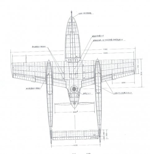
Shinden had six air intakes outside of the fuselage, which were
(1) Engine cooling two big size intakes locared both side of the fuselage.
(2) Two Ram air intakes beside of the engine cooling intakes.
(3) Two oil cooling air intakes located engine end.
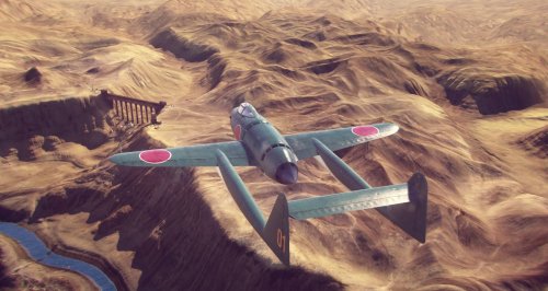
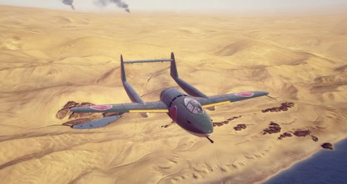
But Senden had no air intakes located outside of the fuselage. Very ideal and radical design.
According to "Zero Fighter" by Jiro Horikoshi , co-authored Masatake Okumiya ,
"In the spring of 1944, when we made the fuselage for the engine experiment and carried out the operation test with a prototype engine, the engine cylinder temperature distribution was good, and it was a prospect of practical use if limited to engine cooling".
(1) Engine cooling two big size intakes locared both side of the fuselage.
(2) Two Ram air intakes beside of the engine cooling intakes.
(3) Two oil cooling air intakes located engine end.
But Senden had no air intakes located outside of the fuselage. Very ideal and radical design.
According to "Zero Fighter" by Jiro Horikoshi , co-authored Masatake Okumiya ,
"In the spring of 1944, when we made the fuselage for the engine experiment and carried out the operation test with a prototype engine, the engine cylinder temperature distribution was good, and it was a prospect of practical use if limited to engine cooling".
Last edited:
Similar threads
-
 Japanese Secret Projects:Experimental Aircraft of the IJA & IJN 1939-1945
- Started by Pelzig
- Replies: 261
-
Mitsubishi J4M1 derivatives /Japanese text
- Started by Tophe
- Replies: 3
-

-

-