Mitsubishi J4M Senden ''Luke'' pusher fighter

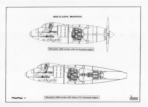
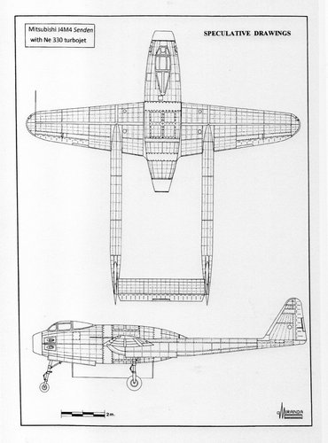
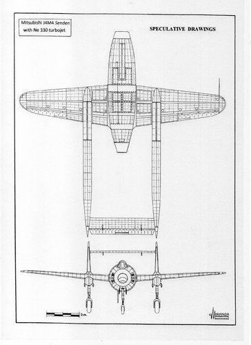
Major Tsuruno, the designer of Shiden, was an engineer of the Imperial Japanese Navy Aviation Technology Arsenal, and was in a position to be familiar with the design details and problems of the Senden.
I think there was a possibility that the design of the Senden, especially engine exhaust system was applied to the Shinden.
 
Hi! I will try to make a abstract of this document.
 

Attachments

  • 188.jpg
    188.jpg
    373.7 KB · Views: 123
  • 189.jpg
    189.jpg
    231.8 KB · Views: 151
  • 190.jpg
    190.jpg
    396.1 KB · Views: 143
Last edited:
Hi! Drawing source : Maru magazine.
Senden early plan in before March 1943                     Modified Senden plan in January to ...jpg
Senden stabilizer.jpg
 
Last edited:
Hi!
Senden prototype official wooden model. (Source : Maru magazine)
I think this model picture is one of the most important evidence of Senden shape.
This model had a six blade normal single proprller, but did not have a bubble canopy.
So transition phase model?
 

Attachments

  • Senden prototype original wooden model.jpg
    Senden prototype original wooden model.jpg
    162.6 KB · Views: 134
Last edited:
Excellent works my brilliant Justo-san!!:cool:
I believe only you can integrate Senden with Ha43-41 engien(with Vulkan coupling dive supercharger) and oil cooler cooled by exaust gas ejector.;)
And please include it to your next book "Fighters of the Rising Sun".:) Then you can get many Japanese fan.:D
 
Last edited:
This picture shows Manshu Ki-98 as you already know.
Ki-98's engine was Ha43-11RU(with single stage two speed machanical supercharger+turbo charger), while Senden's engine was Ha43-41(with single stage two speed mechanical supercharger+Vulkan coupling drive mechanical supercharger).

You can see Ki-98 engine mechanical supercharger at front of the engine.
Turbo charger and mechanical supercharger were connected with air duct.
Fresh air route to engine is as follows.
(1) Ram air intake
(2) Turbocharger
(3) Inter cooler
(4) Mechanical supercharger
(5) Engine cylinders
Unfortunately we can't see oil cooler and engine supply air duct/engine exhaust gas nozzle in this drawing. Oil cooler position is mystery, too.
If oil cooler is located front of the engine, the engine was surrounded by hot air which had bad influence for engine cooling.


Manshu Ki-98.jpg
 
Last edited:
Excellent works my brilliant Justo-san!!:cool:
I believe only you can integrate Senden with Ha43-41 engien(with Vulkan coupling dive supercharger) and oil cooler cooled by exaust gas ejector.;)
And please include it to your next book "Fighters of the Rising Sun".:) Then you can get many Japanese fan.:D
I feel very honoured by your words
 
Intercooler cooling air duct is omitted in your drawing. It's better to add it.
I think ventral air intake is used for engine ram air intake, intercooler cooling air intake and oil cooler cooling air intake.
And oil cooler and intercooler are located side by side, both side of the engine cooling air duct.
Also I think that forced cooling fan is located tail end of the fuselage same as Shinden.
This forced cooling fan will discharge engine cooling air, intercooler cooling air and oil cooler cooling air.
I prefer Shinden like fuselage tail shape for Ki-98.
 

Attachments

  • original drawing tail.jpg
    original drawing tail.jpg
    1 MB · Views: 164
Last edited:
Senden, Shinden and ki-98 are getting confused.
 
Last edited:
Senden, Shinden and ki-98 are getting confused.View attachment 620814
Maybe, but has it ever been discussed, how the the two aircraft, J4M and Ki-98 were so similar? They even used the same engine, but different versions. Another thing that is interesting is that the Ki-98 was to have a turbo supercharger but it's estimated top speed was lower than the estimate for the J4M, at least according to specs in Wikipedia (I know, not the final authority but I'm pretty sure they got their specs from other published material).

So if Wiki is not wrong about the numbers, why the difference is speed? The horsepower of the engines is almost the same and the weight is almost the same. The Ha-211-RU in the Ki-98 makes a little more hp than the MK9 version in the J4M yet the J4M is faster. The J4M IS about 100 Kg lighter than the Ki-98 but would that be enough to account for the difference in speed? I would think that the 100 hp advantage in the Ki-98 would more than make up for the 100 Kg advantage in the J4M.

Could it be aerodynamics? Or something else?

Wikipedia specs for J4M:
  • Gross weight: 4,400 kg (9,700 lb)
  • Max takeoff weight: 5,255 kg (11,585 lb)
  • Powerplant: 1 × Mitsubishi MK9D 18-cyl. two-row fan assisted air-cooled radial piston engine, 1,600 kW (2,100 hp) at take-off 1,416.8 kW (1,900 hp) at 2,000 m (6,562 ft) 1,230.4 kW (1,650 hp) at 8,000 m (26,247 ft)
  • Propellers: 6-bladed metal constant speed propeller, 3.2 m (10 ft 6 in) diameter
  • Maximum speed: 756 km/h (470 mph, 408 kn) at 8,000 m (26,247 ft)
  • Cruise speed: 462 km/h (287 mph, 249 kn)
  • Landing speed: 147 km/h (91 mph)
  • Endurance: 2 hours 12 minutes
  • Service ceiling: 12,000 m (39,000 ft)
  • Rate of climb: 8.89 m/s (1,750 ft/min)
  • Time to altitude: 8,000 m (26,247 ft) in 15 minutes
  • Wing loading: 199.69 kg/m2 (40.90 lb/sq ft)

Wikipedia specs for Ki-98:
  • Gross weight: 4,500 kg (9,921 lb)
  • Powerplant: 1 × Mitsubishi Ha-211 Ru 18-cyl. fan assisted air-cooled radial engine, 1,600 kW (2,200 hp)for take-off
    • 1,461.6 kW (1,960 hp) at 2,000 m (6,562 ft)
    • 1,305 kW (1,750 hp) at 8,500 m (27,887 ft)
  • Propellers: 4-bladed metal constant speed pusher propeller driven by a 2 m (7 ft) long extension shaft, 3.6 m (11 ft 10 in) diameter
  • Maximum speed: 730 km/h (450 mph, 390 kn) at 10,000 m (32,808 ft)
  • Range: 1,249 km (776 mi, 674 nmi)
  • Endurance: 2 hours 15 minutes at 499 km/h (310 mph)
  • Service ceiling: 10,000 m (33,000 ft)
  • Rate of climb: 15.15 m/s (2,982 ft/min)
  • Time to altitude:
    • 5,000 m (16,404 ft) in 5 minutes 30 seconds
  • Wing loading: 187.5 kg/m2 (38.4 lb/sq ft)
 
How much difference can you attribute to the prop drag? Time to height and rate of climb appear better for the Ki-98.
 
This chart is good compared with windswords-san's contribution.

「ハ四三」各型性能 : HA43 engine each model performance
馬力 : hp, 高度 :altitude, 発動機型式 : engine type
使用機体名 : engine installed aircraft name
「ハ四三」一一型(ル) : Ha43-11 (Ru) type (with single stage two speed mechanical supercharger +single stage turbocharger)
烈風改 : Reppu-kai, 連山(改) : Renzan-kai, (and Manshu Ki-98 fighter)
「ハ四三」二一型 : Ha43-21 type
「ハ四三」四二型 : Ha43-42 type (with single stage two speed mechanical supercharger+Vulkan coupling(continuous variable transmission) drive single stage twin blade mechanical supercharger)
震電 : Shinden (No.1 and No.2 prototype) and Senden(almost same engine Ha43-41)
「ハ四三」四三型
: Ha43-43 type (with single stage two speed mechanical supercharger+Vulkan coupling(continuous variable transmission) drive single stage single blade mechanical supercharger)
震電 : Shinden (No.3 and No.4 prototype)
「ハ四三」四四型 : Ha43-44 type (with single stage three speed mechanical supercharger)
震電 : Shinden( No.8 prototype)
ha43.png
 
Last edited:
Senden had a aerodynamically very clean shape fuselage with low drag middle wing.
Ki-98 had a ventral airintake outside of the fuselage with slightly high drag low wing.
Ha43-11 (Ru) type for Ki-98 had higher power compared with Ha43-41 (42) for Senden (and Shinden) at all altitude.
So time to height and rate of climb appear better for the Ki-98.

Wing loading(kg/m2,(gross weight)) Senden : 200, Ki-98 : 187, Shinden : 241
Power loading(kg/hp,(8000m)) Senden : 2.6, Ki-98 : 2.57, Shinden : 3.0
SENDEN KI98 SHINDEN.jpg
 
Last edited:
Thank you for this information Blackkite.
Looks like 「ハ四三」二一型 : Ha43-21 type is the best at maintaining its horsepower rating at all altitudes.
 
Last edited:
17-shi land base high altitude fighter J3K had a Mitsubishi MK9B(HA-43-21) engine with vulkan coupling drive first stage supercharger and mechanical drive second stage supercharger same as Shinden MK9D engine. So J3K had engine side air intakes for vulkan coupling drive supercharger same as Shinden.
I imagine MK9B engine shape looks like MK9D engine. But MK9B engine was for tractor type propeller, vulkan coupling drivwe supercharger was located behind the engine. Shinden MK9D pusher propeller engine vulkan coupling supercharger was located front of the engine.

I can't understand the reason of rapid power down of Ha43-21 type engine at 9500m.Engine over heating limit?
 
Last edited:
Mitsubishi Senden's mid-wing might have produced the lowest drag, but it would have also been the heaviest. Nesting the engine between wing spars is a complex structural and air flow problem. It would need a heavy ring spar/bulkhead to carry span-wise structural loads around the engine. Routing cooling air around wing spars would also be a major hassle ... doubly so back in the days when internal air flow was poorly understood.

The second version's (Ki-98) low wing simplifies wing structure and permits main landing gear that is both shorter and lighter.
It is a mystery why the second version's wing has a straight leading edge and a trailing edge that sweeps forward. The opposite would be easier to balance.

Balance is the other major problem. Airplanes with single pusher propellers are always difficult to balance. All three Japanese pushers mentioned in this thread need long drive shafts to connect propellers to engines. Engines need to be near the center of gravity for balance, but propellers still need to be aft of the wings' trailing edge. Most early jets (DH Vampire, F-86 Sabre and early MIGs all mounted their engines near the C. of G.).

Long drive shafts were problematic with piston engines. First, they need to be perfectly balanced. Secondly, shafts cannot flex during high G maneuvers and finally they need some way to absorb complex torsional vibration created by piston engines. Helicopters only solved torsional vibration problems when they converted to turbine engines during the 1950s.

Even the Shinden canard needed an extension shaft to mount the propeller aft of the wings' trailing edge(s). I would like to know more about Shinden's balance. Was it like the Curtiss Ascender? Ascender was essentially a flying wing with a tiny canard trimming surface.

OTOH, was Shinden balanced like many of Burt Rutan's (post 1970) canards with the forward horizontal surface producing a significant amount of lift? Note that most of Rutan's canards still needed swept main/rear wings to move the C. of Lift aft in order to balance.
 
Shinden first flight data.
Source : 異端の空(Heretic aviation, Pacific War Japanese warplane secret memoir) : ISBN4-16-724909-X , Bungei Shunjuu Co,Ltd (page 328)
(1) Center of Gravity : -14% MAC
(2) Main wing flap : 20°
(3) Front wing flap : 26°
(4)The inclination-to-the-right slant by propeller torque was hard(10°). Operated the aileron to the limit of the left, it was not able to correct.

The second test flight situation of Shinden
(1) Although the elevator was operated to the limit of a rise during the rise, the nose of an airplane fell.
(2) The inclination-to-the-right slant by propeller torque was hard(10°). Operated the aileron to the limit of the left, it was not able to correct.
No data for C.G.

Shinden’s main wing was a laminar flow wing, maximum thickness located 45% wing chord.
Wing root and wing tip angle of attack was 0 degree while wing middle position's angle of attack was 3 degee.
Front wing area was 10% of main wing area.
Front wing span and wing chord were 1/3 of main wing.
Front wing aerodynamic effect to the main wing was small.
Front wing had leading edge slat and double flap (slotted flap + plain flap).
Double flap also had the function of elevator.
Angle of attack of front wing was 1 degree.
 
Even the Shinden canard needed an extension shaft to mount the propeller aft of the wings' trailing edge(s). I would like to know more about Shinden's balance. Was it like the Curtiss Ascender? Ascender was essentially a flying wing with a tiny canard trimming surface.
I am recalling this from memory but I read a story about a guy who built an RC model exactly to scale of the original J7W Shinden. The prop had an extension shaft also. He found that the aircraft had a lot torque pull to one side. He was able to move the engine I believe a few degrees to one side to counteract it. I believe the original aircarft had a similar problem. I don't remember if the modeler did anything else to his plane besides that. Not exactly COG balance but similar. I believe Blackkite has said before that a production J7W would have used a 4 blade prop. Was that because of torque issues with the heavier 6 blade one?
 
Shinden's rolling problems can be explained by "P factor." P factor explains why the descending propeller blade pulls harder because it has a steeper angle of attack during climb. Since Shinden's propeller turned counter-clockwise (as seen from the rear) the left/descending blade pulls harder, trying to turn the nose to the right. Test pilots reported struggling to correct the right rolling tendency with full aileron deflection.

Asymmetric thrust is further complicated by the right/ascending blade operating in turbulent air disrupted by the right wing and fuselage.

A third factor is the short tail moment arm between the centre of gravity and the rudders. That short moment arm meant that rudder(s) alone was not enough to control asymmetric thrust. Many other canard and flying wing prototypes suffered similar problems with poor yaw stability and control caused by locating rudders too close to the trailing edge/C. of G.

Many model airplanes and a few light singles tilt the thrust line/crankshaft 2 to 5 degrees down and/or sideways to counteract P factor.

Dear blackkite,
I am not clear when you say centre of gravity was -14 % Mean Aerodynamic Chord. Are you measuring only the main wing or the total lifting surface?
We are not even sure if Japanese designers considered the canard as a lifting surface.
Which datum were they using to measure C. of G.?
Did they measure starting at the nose (modern practice)?
The minus symbol (-14 %) implies that the C. of G. was short of the MAC. If the C. of G. was 14 % ahead of the MAC of the main wing, that agrees with Burt Rutan's canard stability concepts.

As for Shinden pitch problems it sounds like the canard was too small and at too shallow an angle of attack. Needing a slat and double flaps implies that the canard was working too hard to lift the nose. The short term solution would be limiting main wing flap extension. The medium term solution would entail increasing canard angle of attack to improve nose up control and ensure that the canard stalled first. But my gut feeling is that the only long term solution would be a larger canard.
 
Last edited:
I am not clear when you say centre of gravity was -14 % Mean Aerodynamic Chord. Are you measuring the only the main wing or the total lifting surface?
We are not even sure if Japanese designers considered the canard as a lifting surface.
Thanks a lot riggerrob-san for professional detailed discussion. Are you an aerodynamisist?
I did not calculate even MAC of the main wing. But I think "Center of Gravity : -14% MAC(main wing MAC?)" means front wing always generate lift to cancel head down moment around main wing A.C. Front wing generate 10% lift of the main wing? Shinden did not balance such a condition?
 
Last edited:
Dear blackkite,
Thanks for the complement, but I am not a professional aerodynamicist, just an enthusiastic, amateur, eyeball-engineer who has been studying airplanes for the last 50 years. If I was any good at math, I would have become an engineer.
I did get distracted by parachutes and worked as a professional skydiver (master parachute rigger and all the various instructor ratings) for 18 years.
 
"I am not a professional aerodynamicist, just an enthusiastic, amateur, eyeball-engineer who has been studying airplanes for the last 50 years."
Me,too.
Professional skydiver!!!:oops:
You are experiencing aerodynamics same as wind tunnel test at every dive.:D
 
I did get distracted by parachutes and worked as a professional skydiver (master parachute rigger and all the various instructor ratings) for 18 years.
So... you made a living jumping out of perfectly good working airplanes? :p I bet you have some stories to tell!
 
Dear windswords,

You obviously have not taken a close look at jump planes.
Most are on their last legs after full careers as airliners or military transports or executive transports. When their radios get too obsolete to fly into large, international airports, they are relegated to the far north. When they can no longer pressurize their cabins, they switch to hauling the mid-night mail. When their de-icing boots no longer inflate, they fly sight-seers for a few more years. After all that hard work they either go to the scrap yard or haul skydivers. Cheapskate skydivers only pay for remaining engine life and the few remaining radios. The tired airframe gets tossed in for free.
Did I mention that skydivers are cheapskates? When forced to chose between replacing a failing pump or buying another round of beer … guess which they buy?

11 years ago I was badly injured when a Beechcraft King Air B90 jump-plane force-landed. That tired turbo-prop left the Beechcraft factory during the late 1960s, so was about 50 years old when its career ended in 2008.
A fuel pump quit, then the pilot shut down the wrong engine. Fortunately the pilot had enough skill to force land in a farm field, up-right and just slightly faster than stall speed. Lacking seat belts, all the skydivers got tossed around inside the cabin.
I struggled through 5 months of physical-therapy before jumping again, but it was a year before I could walk without pain.
Then lawyers dragged out lawsuits for 7.5 years, but after 11 years, legal paperwork is far from complete.

The good news is that my fear of airplane crashes has been replaced by an allergy to lawyers.
 
Over on the Shinden thread, post #157 shows the centre of gravity almost at the main wing root leading edge, so it definitely needed the canard lifting to fly level.

Some pictures over there also show three intakes per side! They probably ruined any chance of smooth airflow into the propeller.
Finally, lowering landing flaps on the main wing would only add more turbulent airflow to the propeller.
I suspect that only the bottom 1/3 of the propeller disc worked in smooth airflow.

Dear moderators,
Please copy and paste this post and #67 to the Shinden thread.
Thanks
 
"The good news is that my fear of airplane crashes has been replaced by an allergy to lawyers.":D
 
Hi! My image for Shinden C.G. (Maiden flight condition)
If this C.G.position is correct, perhaps front wing generated larger lift compared with it's wing area at maiden flight.
 

Attachments

  • Shinden MAC, AC and CG.jpg
    Shinden MAC, AC and CG.jpg
    127.7 KB · Views: 180
Last edited:
Hi,

I can't understand the reason of rapid power down of Ha43-21 type engine at 9500m.Engine over heating limit?

I can only speculate. Overheating would seem like a possiblity, as air-cooled engines have a hard time getting rid of heat at high altitudes. Another possible reason for the power reduction might be a deliberate reduction in engine speed to keep the propeller tip Mach number down, in order to keep compressiblity-induced efficiency losses at a tolerable level.

If the Ha-43 versions in question use water-methanol at the indicated power, it could also be a question of switching anti-detonant injection off above full throttle height, as detonation might not be a serious factor when you can't get full boost pressure up high. The charge cooling effect as well as the calorific value of the alcohol might warrant not switching it off directly upon reaching full-throttle height, but there's probably an altitude above which you'd decide to consider it uneconomic to keep it running.

Regards,

Henning (HoHun)
 

Similar threads

Back
Top Bottom