DoggoVision

ACCESS: Restricted
Joined
27 June 2025
Messages
24
Reaction score
22
Hello, I recently became interested in the MIG-29M and K.

Please correct me if im erroneous, but from what i've gathered is; there exists two general variants of the MiG-29M. The 9-15 prototype from the 80's and 90's, and the 9-41. (2000's) The latter was developed into the MiG-29K as we know it today, though it's roots are traced back to the original 9-15.

1778293362177.png

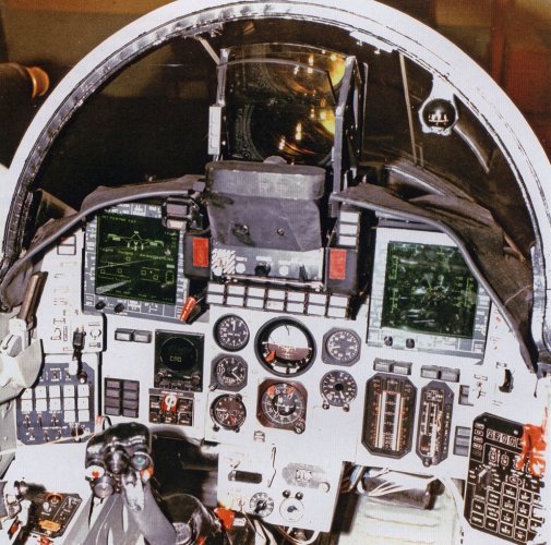
In researching the original 9-15, and found this photo of it's cockpit, this is a 90's variant 9-15 or MiG-29K. My biggest question is: what MFDs are these? They appear not to have any buttons.


Any help in finding sources is helpful. Thank you
 
MiG-29K.jpg
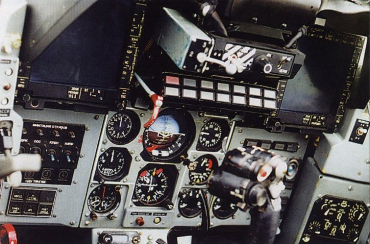
This is the MiG-29K cockpit from a mockup front fuselage. Next two are actual MiG-29M (9.15) cockpit.

MG-29M-1.jpg MG-29M-2.jpg
Information on the MiG-29M HUD and CRT development can be found here: https://www.litres.ru/book/matvey-z...2-uroki-zhizni-35484928/chitat-onlayn/?page=8 (memoirs of a key engineer, it has lots on the standard MiG-29/Su-27 HUD/CRT development too)

Cathode Ray Tubes and Instruments for 3rd Generation Information Display Systems

As is well known, the head-up displays (HUDs) included in the IPP-2-53, SEI-31, and Narcissus systems utilize the Kunitsa projection CRT. This PELT is also known to have a number of drawbacks, the main ones being the "screen effect"—the presence of a residual screen glow at night and the formation of halos around image elements when brightness is increased, which reduces contrast. The causes of these drawbacks in the Kunitsa PELT and methods for mitigating them have been discussed above. Therefore, during the development of the KAI-1, the need to create a new, improved PELT with higher brightness and resolution and devoid of these drawbacks became urgent. The Platan Research Institute began developing a similar PELT in the early 1980s. This PELT, called "Latex," was a tube with a ceramic envelope using leucosapphire as the screen, which has higher thermal conductivity than glass. With an anode voltage of 18 kV and mixed (magnetic and electrostatic) focusing, the "Lateks" PELT, according to the developers, was expected to provide high brightness, greater resolution, and significantly longer life than existing PELTs. Considering that the claimed characteristics of the "Lateks" PELT significantly exceeded those of the "Kunitsa" PELT, a new tube was incorporated into the KAI-1 design. However, during testing of the KAI-1, the claimed characteristics of the "Lateks" PELT were not confirmed. This was due to the PELT developers' miscalculation of the phosphor capabilities and the reliability of the bonding technology between the ceramic envelope and the leucosapphire. The point is that as the brightness was increased, the phosphor saturated, and the expected proportional increase in brightness did not occur. Instead, critical heating of the screen occurred due to localized concentration of radiant energy. It was this latter factor that necessitated the use of leucosapphire. Furthermore, during bench and flight tests, including factory tests of the MIG-29M aircraft, frequent failures of the Latex PELT occurred due to leaks, leading to complete failure of the KAI. Almost all Lateks PELTs manufactured by the Platan Research Institute failed within a relatively short period of time. Only a small reserve of these tubes and a well-organized repair service at NIO-2 allowed flight tests of the aircraft to continue for some time. Another significant drawback of the Lateks PELT is the hard X-ray radiation it generates, especially in the direction of the tube axis. The tube's screen, made of leucosapphire, unlike the glass in conventional CRTs, does not block radiation levels several times higher than the permissible limit. Since the preliminary adjustment of the PELT control unit is performed without the optical head attached, adjusters could be exposed to strong radiation when turning it on. These objective facts were established by specialists from the V. G. Khlopin Institute, who conducted corresponding measurements at workstations within the Association. At the Institute's recommendation, the necessary radiation protection measures were implemented at these workstations. Finally, regarding the "Lateks" PELTs, it should be noted that these PELTs are extremely expensive: in 1986 prices, it was 2,500 rubles per sample.

In 1987, On the initiative of M. Z. Lvovsky and V. A. Sysoev, supported by the Association's General Director, K. K. Filippov, and in accordance with the Technical Specifications approved by him, the plant (MELZ) began developing an alternative PELT based on the Moscow "Kunitsa" PELT bulb, dubbed "Koma." The development of the new PELT received the support of the Ministry of Defense, which instructed the relevant services to continuously monitor the development process. The development of the "Koma" PELT utilized the latest advances in electron optics and incorporated a modern technology based on laser processing of the focusing elements of the PELT's electron optics. The use of an improved phosphor, combined with a successful optical design, made it possible to achieve very high performance at an anode voltage of 15 kV and a focusing electrode voltage of 2 kV. The brightness of the Koma PELT (in a compressed raster) is twice that of the Kunitsa PELT, reaching 12,000–14,000 cd/m², and the resolution is increased by 30 (line width 0.08–0.1 mm). The "screen effect" and halo formation when boosting brightness are virtually eliminated. The working tube diameter is 55 mm, the neck diameter is 22 mm, the flare angle is 55°, and the tube length is 220–230 mm.

The cost of the Koma PELT was 200 rubles in 1987–1988 prices, or 12.5 times lower than the cost of the Lateks PELT, with identical characteristics. The development of the Koma PELT made it possible to promptly resolve the crisis that arose as a result of the failure of the Lateks tube. In a short time, the KAI-1 design was developed based on the Koma PELT (Lead Designer F. D. Zharzhavsky), and all previously manufactured indicators were modified. In 1988, state testing of the Koma PELT was completed, and it received certification for use in military equipment.


Monochromatic CRT for ELI cathode-ray indicators.

While developing the concept for building third-generation information display systems, which include the KROKUS and EDELWEISS systems, the Association studied the state of development in the field of direct-view cathode-ray tubes and their future development prospects. The research results revealed that the Soviet electronics industry lagged significantly behind the global market in this area. This was especially true for color (mask) CRTs suitable for use onboard cannon-armed fighters. Moreover, there was no reason to expect any changes in this area in the coming years, which subsequently proved to be true. Given these and other circumstances, the decision was made to design ELI based on a monochromatic CRT. This decision was not uncommon in international practice. An example of a similar approach is the information display system on the F-18 fighter, which was recognized as meeting the requirements for integrated display systems for aircraft of this type. Monochromatic CRTs in direct-view displays like the ELI are square, with a working screen size of 127 mm x 127 mm. The developers of this system assumed that the high brightness of the CRT would ensure, through luminance contrast, the reliable perception of all graphic image elements, even when they differ in shape and location, based on the fundamental principles of engineering psychology.

At an extended meeting of the Council of Chief Designers at the Mikoyan Moscow Machine Building Plant, attended by representatives of the MAP research institutes, the Association's viewpoint on the design principles of the KROKUS information display system was presented by the author, Deputy Head of NIO-2, at the request of the Association's General Director, K. K. Filippov. Despite the compelling arguments presented in support of the Association's proposals, representatives of the leading MAP institutes (LII, NIIAS) categorically opposed the Association's concept, insisting on the use of penetrons in the ELI. This was despite the fact that the futility of this type of CRT was already obvious at the time, having even been abandoned by its French creators. Toshiba and Intel revolutionized this field by creating a high-brightness color liquid crystal display panel with an internal backlight and an integrated control system. Within a short time, electronic display systems were developed based on these panels, which were installed on production Boeing 757 and 767 aircraft. Unfortunately, the domestic electronics industry did not have such capabilities. Therefore, the KROKUS developers had no alternative but to use a monochromatic tube similar to the F-18.

Mikoyan Machine Building Plant Deputy Chief Designer Yu. A. Yanyshev soon recognized the Association's position as the only viable one. Thanks to him, the Ministry of Electronics Industry coordinated all technical and organizational issues related to the development of a new monochromatic CRT for electronic devices, featuring high brightness and high resolution, as well as the selection of a developer. This was the Platan Research Institute, with which the technical specifications for the CRT development and the development program were agreed upon. For the first time in the Ministry of Electronics Industry, Platan Research Institute implemented a comprehensive approach to CRT development, taking into account real-world operating conditions at the facility and factors ensuring the achievement of the best CRT performance. The institute's electron beam device, dubbed "Litva," includes the CRT itself, a focusing and deflecting system (FDS), and an electromagnetic shield with device mounting elements in the display. The "Litva" EBT is manufactured using modern technology and has flexible leads, including high-voltage leads. The space between the CRT bulb and the electromagnetic shield is filled with a special compound, ensuring the rigidity of the CRT structure.

The "Litva" CRT is equipped with an anti-glare filter with an anti-reflective coating on the first surface. The filter's absorption coefficient is 90%. To protect the coating from damage, the CRT is supplied with a special soft cap. The high-quality filter allows for the viewing of not only symbolic information generated by the functional method, but also raster, multi-gradient images with 67 gradations at a maximum ambient illumination of 100,000 lux. The flare angle of the CRT bulb is less than 50°, reducing power consumption by 40° compared to the "Malyshka" CRT. The main characteristics of the "Litva" ELP: screen size 130mm x 130mm, dimensions 145mm x 145mm x 350mm, anode voltage of 16kV, line width of 0.20-22mm, service life of 1000 hours. The "Litva" ELP has successfully passed state tests for compliance with the requirements for military aircraft components.

The acceptance by the Mikoyan Machine Building Plant of the concept for constructing the KROKUS information display system for the MiG-29M aircraft, proposed by the Association, and the real assistance in organizing the work related to the creation of new electronic components, in particular the "Litva" electronic control system, allowed the Association to begin developing and manufacturing prototypes of the KROKUS system. It is worth noting the positive role of F. D. Zharzhavsky, KROKUS 's lead designer, in the creation of the "Litva" electronic control system. His rational proposals for the external contours of the tube and its mounting method were taken into account during its development.

The development of the KROKUS system was carried out in accordance with the technical specifications agreed upon with the Mikoyan Machine Building Plant and the Air Force. Prototypes of the KROKUS system were manufactured in late 1988. Following laboratory debugging, two prototypes of this system were sent to the Institute of Space and Aviation Medicine for testing on a simulator created based on the actual cockpit of a MIG-29M aircraft and to the Integrated Department of the Association for bench testing as part of the Scientific and Production Complex. The third prototype of the KROKUS system was subjected to bench testing for compliance with the requirements of the Technical Specifications. The tests revealed that the prototype of the KROKUS information display system, in terms of its accuracy, optical, and lighting characteristics, fully complied with the requirements of the Technical Specifications and outperformed all previously developed systems for a similar purpose. In 1987–1988, to support flight tests of the MIG-29M aircraft, an intermediate version of the information display system was created, consisting of KAI-1 and ELI indicators and SEI-31 units: TsVM20–6, GS-31, BP. Corresponding software was developed for this system. It was during the factory testing process that the defects of the Lateks CRT, which were mentioned above, were discovered.

 
Last edited:
What's on screen looks quite a lot like the IT-23M display used on the Su-22/Su-24 with the Kh-29T, though that is more yellow than green - but this is probably because its what the Kh-29T output looks like.
 
I was just looking at the Yak-41 MFD as a possible candidate. It doesn't seem to be an exact match either, but to me the display on the MiG-29SM seems to be a bit bigger than the IPV, and the control knob seems to be close to the lower left corner rather than lower middle position?
 
According to memories mentioned in this thread, IPV had screen ratio 4:3 and diagonal 15cm: so 12cm width and 9 cm height, and screens designed to Mig-29M were rectangular 13cm x 13cm
Display from Yak-41 seems to be rectangular, with two knobs the same as in picture Mig/29K mockup.
 
Last edited:
Yes, the Yak-41 has the 13 x 13cm display same as the MiG-29K mockup cockpit. The MiG-29M cockpit shots show square MFDs (also 13 x 13 cm) but they aren't quite the same. Maybe test items?
 
According to memories mentioned in this thread, IPV had screen ratio 4:3 and diagonal 15cm: so 12cm width and 9 cm height, and screens designed to Mig-29M were rectangular 13cm x 13cm
Display from Yak-41 seems to be rectangular, with two knobs the same as in picture Mig/29K mockup.
I checked once again in IPV diagonal is 16cm ( not 15) so diameters are: 16/5=3,2
w: 4x3.2=12,8
H: 3x3.2=9,6

So width was the same as in later Mig-29M , height was ~10cm
 
There were two differ MFD's in the two prototypes of MiG-29SM , one as standard CRT/ IPV and second as MFD from the MiG-29M.

''Отработка применения управляемого оружия «воздух-поверхность» с телевизионными ГСН проводилась с 1995 г. на опытном истребителе МиГ-29 №405 и переоборудованном серийном МиГ-29 №4711, при этом у первого изображение местности передавалось на штатный индикатор прямого видения (ИПВ), а у второго - на установленный вместо него монохромный электронно-лучевой индикатор, применяемый в СОИ самолетов МиГ-29М.''


''The use of air-to-surface guided weapons with television homing heads was tested starting in 1995 on the experimental MiG-29 fighter No. 405 and the converted serial MiG-29 No. 4711. In the first case, the terrain image was transmitted to the standard direct-view indicator (DVI), and in the second case, to a monochrome electron-beam indicator installed in its place, used in the SDI of MiG-29M aircraft.''

http://www.airwar.ru/enc/fighter/mig29sm.html
 
I'm trying more info on what information or interface graphics were presented in the displays on the 29M, does anyone have any info on that specific area?
 
There were two differ MFD's in the two prototypes of MiG-29SM , one as standard CRT/ IPV and second as MFD from the MiG-29M.

''Отработка применения управляемого оружия «воздух-поверхность» с телевизионными ГСН проводилась с 1995 г. на опытном истребителе МиГ-29 №405 и переоборудованном серийном МиГ-29 №4711, при этом у первого изображение местности передавалось на штатный индикатор прямого видения (ИПВ), а у второго - на установленный вместо него монохромный электронно-лучевой индикатор, применяемый в СОИ самолетов МиГ-29М.''


''The use of air-to-surface guided weapons with television homing heads was tested starting in 1995 on the experimental MiG-29 fighter No. 405 and the converted serial MiG-29 No. 4711. In the first case, the terrain image was transmitted to the standard direct-view indicator (DVI), and in the second case, to a monochrome electron-beam indicator installed in its place, used in the SDI of MiG-29M aircraft.''

http://www.airwar.ru/enc/fighter/mig29sm.html
The one in the video i posted seem to be bort 331, would it be serial 4711 (with the MiG-29M MFD) or another airframe?
 
The one in the video i posted seem to be bort 331, would it be serial 4711 (with the MiG-29M MFD) or another airframe?
I don't think its the one with the Mig-29M MFD because the 29M mfd has writing and cues on the borders of it
 
The one in the video i posted seem to be bort 331, would it be serial 4711 (with the MiG-29M MFD) or another airframe?

It was in fact prototype MiG-29SM , 9.13SM No 405 . There were two prototypes of the 'SM' : 9.12SM and 9.13SM. From the same source :

''Зарубежная премьера МиГ-29СМ состоялась на авиасалоне в Ле Бурже в июне 1995 г., где демонстрировался опытный самолет МиГ-29 №405, получивший «выставочный» №331 и оснащенный разнообразным управляемым вооружением классов «воздух-воздух» и «воздух-поверхность». Позднее роль МиГ-29СМ на международных выставках (в Берлине в 1996 г. и в Париже в 1997 г.) «играл» опытный МиГ-29 №4808 (бортовой №357, «выставочный» №353) с системой дозаправки топливом в полете.''

''The MiG-29SM's international debut took place at the Le Bourget Air Show in June 1995, where prototype MiG-29 #405, designated "exhibition" #331 and equipped with a variety of air-to-air and air-to-surface guided weapons, was on display. Later, prototype MiG-29 #4808 (tail number 357, "exhibition" #353), equipped with an in-flight refueling system, played the role of the MiG-29SM at international exhibitions (in Berlin in 1996 and Paris in 1997).''
 
The MiG-29K mockup shows a flaps display on the left and what looks like a HUD display on the right.
View attachment 811802
View attachment 811803
I wonder if these two displays (in practice) only were used for flight data or as placeholder. I'd like to think the software possibly didn't reach maturity for weapons systems since the program was cancelled circa 1991. Every other Mig-29K and later the M in the 2000s uses two push-button liquid crystal MFDs that we are familiar with
 
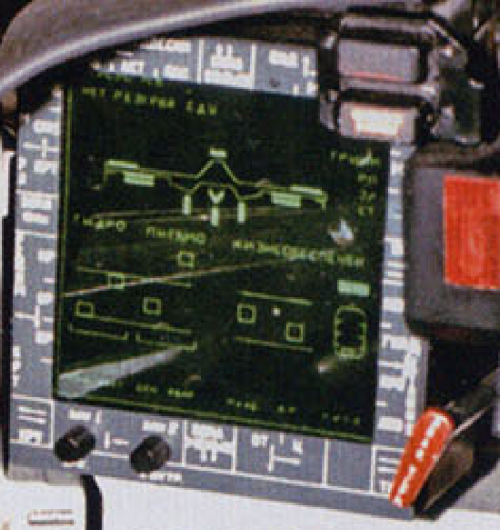
I've taken a screenshot. Maybe i'm wrong, but still doesn't look like the standard IPV to me. Looking at the MiG-29M cockpit above, could it be a MiG-29M MFD but without the writing?
1778437769656.png
 
Well, there is an immense technical gulf between 1986 and the 2000s. In 1986 the USSR was using monochrome 'green screen' CRT monitors after abandoning 3 colour (red / yellow / green) penetron CRT displays. LCD displays were a far-off prospect in 1986.
 
I've taken a screenshot. Maybe i'm wrong, but still doesn't look like the standard IPV to me. Looking at the MiG-29M cockpit above, could it be a MiG-29M MFD but without the writing?
View attachment 811801
Looking at this screenshot I see it has the two knobs the mig-29K and Yak-41 share. From what I've gathered about the mock up and Mig-29M is that the writing was likely instructions for how to navigate the MFD software. The MFDs obviously lack hotkeys, and were instead manipulated using HOTAS (my guess is with a hat or dobber, as the writing shows different arrows and cues, likely for which directions to move said hat or dobber as they correspond to each page) It looks like it could be the same CRT display, though I'm not sure why they wouldn't apply the markings to it in these prototypes.
 
I've taken a screenshot. Maybe i'm wrong, but still doesn't look like the standard IPV to me. Looking at the MiG-29M cockpit above, could it be a MiG-29M MFD but without the writing?
View attachment 811801
It could be. I see the two knobs now in the screenshot. It does look squarer and taller, and has what looks to be a bezel type area which could where the writing is on the other displays.
 
Looking at this screenshot I see it has the two knobs the mig-29K and Yak-41 share. From what I've gathered about the mock up and Mig-29M is that the writing was likely instructions for how to navigate the MFD software. The MFDs obviously lack hotkeys, and were instead manipulated using HOTAS (my guess is with a hat or dobber, as the writing shows different arrows and cues, likely for which directions to move said hat or dobber as they correspond to each page) It looks like it could be the same CRT display, though I'm not sure why they wouldn't apply the markings to it in these prototypes.
Yes, that's what I assumed. Perhaps each "text cue" could be associated with an on-screen indicator which one(s) applied to each screen?
 
It could be. I see the two knobs now in the screenshot. It does look squarer and taller, and has what looks to be a bezel type area which could where the writing is on the other displays.
another possible idea is it runs a different software than the mockup of the 29K and 29M. Would you agree that it isn't too far-fetched to say that the mockup could have used placeholder displays, that do not match what was actually shown?
 
Yes, that's what I assumed. Perhaps each "text cue" could be associated with an on-screen indicator which one(s) applied to each screen?

Hmm…come to think of it, in the photo of the flight control systems page of the Mig-29K mockup, there appears to be some border text, which definitely supports what you said
 
I’ve been very interested in the original Mig-29m/k for a long time unfortunately not much available. This NASIC translation of an article by one of the engineers has some info.
Instead of
the conventional analogous equipment the 29M version has two
multifunction monochromatic monitors. The one on the right
displays incoming information from the radars, infrared bearing
devices, TV cameras and laser telemeters for the control and
regulation of firing. The one on Th left displays flight
values, navigational information, furnishes a landing system via
the ILS (Instrument Landing System), the state of the equipment
as well as tactical and other auxiliary data. The display can be
made to function according to the requirements of the setup and
thus the left might be used in respect to ground targets and the
right for air targets.

In 1991 some General Dynamics engineers where allowed to sit in a MiG-29m or K cockpit simulator, their is a trip report but I don’t know how to go about finding it.

During a visit to the Research Institute of Aerospace Medicine in Moscow in May

1990, Kevin Dwyer of General Dynamics had a chance to fly a simulator for what was

described as an "advanced cockpit design" aircraft. He reported that it was basically a

MiG-29 cockpit with conventional flight instruments in the center and two cathode-

ray-tube displays. His account of the simulator's ADI operation was reminiscent of my

own experience in the MiG-29: ''The horizon line on the simulator display was

airplane-stabilized, not earth-stabilized (as in Western displays). The aircraft symbol

relationship to the horizon line is the same as in our aircraft, i.e., a 30-deg right bank

places the right wing 30 deg below the displayed horizon. However, the different hori-

zon stabilization means that the airc.·aft horizon reference is at variance with the true

horizon, and the displayed airplane symbol position relative to the earth's horizon is

actually twice the true bank angle" (informal trip report, July 2, 1990, p. 7).

https://apps.dtic.mil/sti/pdfs/ADB165245.pdf
 

Attachments

  • Mig-29m.pdf
    13.3 MB · Views: 21
I’ve been very interested in the original Mig-29m/k for a long time unfortunately not much available. This NASIC translation of an article by one of the engineers has some info.


In 1991 some General Dynamics engineers where allowed to sit in a MiG-29m or K cockpit simulator, their is a trip report but I don’t know how to go about finding it.


https://apps.dtic.mil/sti/pdfs/ADB165245.pdf
This is some incredible information and provides tons of insight on how the MiG-29M’s system logic worked! Thank you so much.
 

Similar threads

Back
Top Bottom