
You are using an out of date browser. It may not display this or other websites correctly.
You should upgrade or use an alternative browser.
You should upgrade or use an alternative browser.
MiG-29 Avionics
- Thread starter overscan (PaulMM)
- Start date
Шурави1983
ACCESS: Confidential
- Joined
- 12 May 2025
- Messages
- 59
- Reaction score
- 58
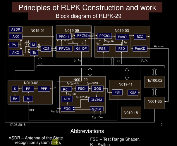
1771954482679.pngWhich piece?
This screenshot (taken from that english N019 PPT) said that IFF was intergrated into N019-01, as it is the antenna of N019. I think some sources mistakenly regard the SZO(the 'answer-er' of IFF) as the 'ask-er' of IFF.
Attachments
Aeria Gloria
ACCESS: Secret
- Joined
- 8 February 2024
- Messages
- 372
- Reaction score
- 431
I’m sorry but I don’t see where these say that IFF is integrated into the emission of the N-019 antenna and not just some block connected to the system with the antenna being referenced being the 3 spikes or bottom triangle.1771954482679.png
This screenshot (taken from that english N019 PPT) said that IFF was intergrated into N019-01, as it is the antenna of N019. I think some sources mistakenly regard the SZO(the 'answer-er' of IFF) as the 'ask-er' of IFF.
I would think if it was from the antenna of the radar, it would also have azimuth resolution. But it doesn’t. Everything at the same range as the friendly aircraft will be marked friendly on the ILS during interrogation.
Шурави1983
ACCESS: Confidential
- Joined
- 12 May 2025
- Messages
- 59
- Reaction score
- 58
Aha, the 3 delta-like things is the difference channel of monopulse radar. And yes, your idea make sense, because the main antenna driver('PA') is not connected to the ASDR(IFF antenna)!I’m sorry but I don’t see where these say that IFF is integrated into the emission of the N-019 antenna and not just some block connected to the system with the antenna being referenced being the 3 spikes or bottom triangle.
Um, If it doesn't, then you idea is definitely correct.I would think if it was from the antenna of the radar, it would also have azimuth resolution. But it doesn’t. Everything at the same range as the friendly aircraft will be marked friendly on the ILS during interrogation.
As I using auto translation reading the material (1771954116892.png from reply #395), the identification of targets is done with azimuth angle. Anyway, auto translation often leads to kinds of error, so yes, I will leave my opinion as a reference.
")
Aeria Gloria
ACCESS: Secret
- Joined
- 8 February 2024
- Messages
- 372
- Reaction score
- 431
Think we might be talking about different things. This “odd rods” similar part of SRO-2 is only for IFFAha, the 3 delta-like things is the difference channel of monopulse radar. And yes, your idea make sense, because the main antenna driver('PA') is not connected to the ASDR(IFF antenna)!

Also

Also apparently, it is off for every 1 out of 5 search cycles for some reason. This does not affect the SNP mode if foe-friend selector is in “don’t lock friendlies” position becuase SNP requires atleast 3 scans before building a track and comparing range vs closure.
Aeria Gloria
ACCESS: Secret
- Joined
- 8 February 2024
- Messages
- 372
- Reaction score
- 431
Squirrel, if you’re still reading this, or Lukas maybe, here is why I kept telling you that if you want to read about N-019 operation during missile guidance, that you NEED to read the chapter about R-27R use, NOT the chapter that says it’s only about search mode and processing of coordinates.
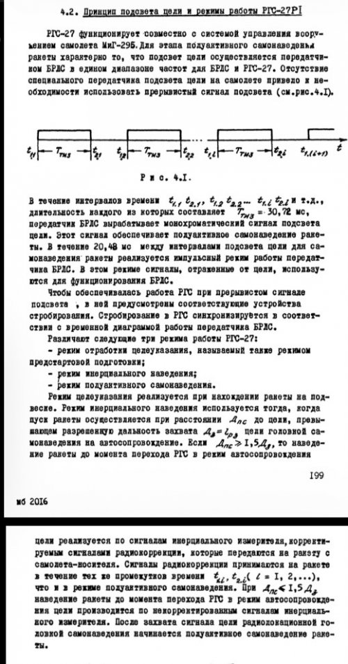
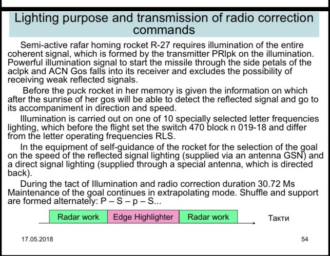
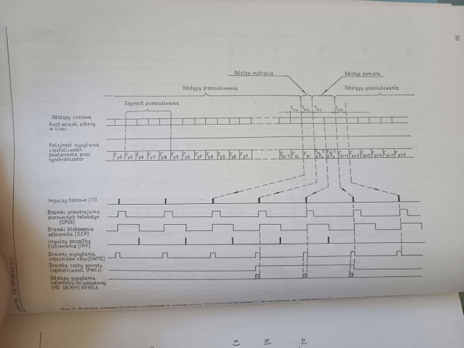
Here is the beginning of the R-27 chapter, it is less then half way through the book. It says that inside datalink range the sequence is 30.72 ms quasi illumination and THEN 20.48 ms for tracking and THEN re starts sequence. It is explicit that this is the configuration in a repeating cycle after seeker has acquired target and before DNP expires at 60s from start. The field marked “TH3” is 30.72 illumination and the gaps are the 20.48 ms tracking period. PowerPoint shows identical information.
Notice the picture shows the exact same sequence from your other figure that shows search sequence then this sequence on the top right side. This clarifies that during DNP after seeker acquisition it is continuously doing this and not switching. It is why these timings are not mentioned in the whole search mode chapter you kept referencing except for this graphic merely trying to show you ahead of time a more complete picture of the radar emission before you got there.
The PowerPoint and the MiG-29B manual both state that during radio correction the sequence is 7x of these sequences of 30.72 ms+ 20.48 ms, then the datalink period of 1/3rd second and the second datalink period if needed before doing 30.72 ms illumination + 20.48 ms tracking for a total of 2/3-1 s radar cycle during datalink phase.
This should show beyond all dispute what the radar is doing during this term in terms of emission. It can’t search while tracking or in such short time frames.
This should put the topic to REST
FOREVER
I hope to never speak of this again, just like Ziggy trying to tell everyone the radar does not use a gimbal which is too advanced and precise for it and instead uses “mechanical scan” or whatever it was he kept claiming was a real thing and not as good as gimbals which meant that N-019 couldn’t use radar at WVR ranges in opposition to literally all documents lmao.


Attachments
Last edited:
- Joined
- 27 December 2005
- Messages
- 18,727
- Reaction score
- 33,162
The N019 and N001 do have integrated IFF interrogators in the antenna, first generation of Soviet radars to do so. The twist-cassegrain reflector array has two layers of dipoles, one reflecting the main radar beam and a set of smaller dipoles reflecting the IFF beam. Colocating the interrogator means the beam is directed at the radar target and doesn't have to be radiated in all directions.
See attached document I machine translated from Russian - I can't find the original Russian copy but this was discussed 20 years ago in the Sapfir-23 topic.
A radar expert said:
See attached document I machine translated from Russian - I can't find the original Russian copy but this was discussed 20 years ago in the Sapfir-23 topic.
A radar expert said:
Having now perused it in detail (using overscan's translation plus a dictionary for the diagrams I am full of admiration for the incredible microwave engineering of the complex feed - incorporating main radar (with multimode horns), E and H-plane sidelobe suppression + overall guard horn (the compensation horn) and Parol Tx/Rx. The sub-reflector means of polarising both frequency bands is phenominal!
Attachments
Aeria Gloria
ACCESS: Secret
- Joined
- 8 February 2024
- Messages
- 372
- Reaction score
- 431
how sure are we that this is specifically about N-019/N-001 and not just twist cassegrain in general?.
A radar expert said:
Why would radar not be included in IFF components in radio electronic RTEs manuals?
Why is there no azimuth resolution if the radar is aware of where it is pointing?
I can believe that radar does interrogation, but with the above limitations I would
Think atleast reception is by the exterior parol antennas.
There are times radar emits with no IFF (1 out of 5 search cycles, quasi search, IRST mode COOP, etc) but those are much easier to explain as being separately turned off
These questions remain
Attachments
Last edited:
- Joined
- 27 December 2005
- Messages
- 18,727
- Reaction score
- 33,162
I don't have proof its N019/N001 described in the document, and I don't know the source other than a Russian user uploaded it, but all the other details of the design described match. Its not how Sapfir-23 was, and no other country ever made a similar system to this to my knowledge that this could be a description of.
MiG-23 used a combined SRZO-2M transmitter/receiver. Su-27SK uses SRO-1P receiver and SRZ-1P transmitter.
The MiG-29/Su-27 does have an omnidirectional IFF receiver, so it's quite possible that the IFF signal is received by those and doesn't need to come back via the radar antenna. There's an out-of-date but interesting IFF discussion here: https://www.secretprojects.co.uk/threads/soviet-russian-iff.792/
Later Russian radars use multiple IFF dipoles on the planar or phased array.
Last edited:
Aeria Gloria
ACCESS: Secret
- Joined
- 8 February 2024
- Messages
- 372
- Reaction score
- 431
After a HUGE amount of reading today, I can say there is an interrogator in the radar antenna. However it never mentions receiving the IFF return through the radar antenna. And signal processing and algorithm chapters do not mention it.The MiG-29/Su-27 does have an omnidirectional IFF receiver, so it's quite possible that the IFF signal is received by those and doesn't need to come back via the radar antenna. There's an out-of-date but interesting IFF discussion here:
Wether the radar antenna receives the IFF signal or it’s the other Parol antennas on the nose, it could be the “range resolution” issue occurs when anything within the main lobe/side lobe of the radar beam receives the same IFF signal and gives the return, creating a chance that any friendly aircraft close to the target enemy (within the 3.5 degree beam or side lobes) AND at a very close range in distance to the radar could be incorrectly marked as friendly.
If there is no need for anything but the radar to receive the IFF signal, it is curious why we have unique IFF aerials above and below the nose despite as you mentioned, there already being a set of IFF aerials situated in the leading edge extensions and tail to cover 360.
Also found interesting info on the targeting circle, it will move to get you to fly from 2-15 km if you are outside this range, and the intercept cue is only designed for about Mach 0.66-Mach 1.5.
Attachments
- Joined
- 27 December 2005
- Messages
- 18,727
- Reaction score
- 33,162
Mounting a directional IFF interrogator in the radar antenna has a lot of benefits. SRZO-2M requires the MiG-23 to broadcast an interrogation signal widely, which can be picked up by ESM systems like COMBAT TREE. WIth the SRZ-1P you mostly only interrogate your target.
- Joined
- 27 December 2005
- Messages
- 18,727
- Reaction score
- 33,162
So, I was able to locate the original source of the Cassegrain Word doc.
Its appears to be a website for a college/university and the Cassegrain document is part of a wider collection of Russian military avionics documents.
Machine translation has got a lot better in the intervening 20 years:
Its appears to be a website for a college/university and the Cassegrain document is part of a wider collection of Russian military avionics documents.
Machine translation has got a lot better in the intervening 20 years:
TWO-MIRROR ANTENNA
1.2. Two-mirror antenna: - general information, construction principle and operating features
The two-mirror antenna is designed for formation of spatial radiation patterns (DP) in order to ensure radar operation in airspace review (Obzor) and recognition modes state affiliation (state identification) and corner auto-tracking detected targets (auto-accompanying).
At the same time, they are formed the following types of DN:
1.IN THE Microwave radio waves:
- DN «needle-shaped» view in airspace viewing mode during antenna operation both for reception and transmission, and when «target illumination» is continuous monochromatic signal;
- compensatory A specially shaped DN when the antenna is operating for reception in viewing modes and auto-tracking;
- total difference DN in auto-tracking mode.
2. IN THE UHF radio waves:
- total difference DN of the state identification system (SGO).
Radiation the antennas are vertically polarized. This ensures gyrostabilization of the DN during aircraft roll evolutions within ± 700.
. For definition spatial coordinates and providing angular tracking of the target hidden conical scanning of difference patterns and amplitude scanning are used processing of signals received by the total and difference patterns is formed digital angular coordinate signals along the azimuth, tilt and roll axes in binary code.
Low side lobe level (SLD) required for effective Doppler filtering of target signals in the radar is ensured formation of a compensation DN of a special form. In reception mode, the level the near and far side lobes in the lower part of the elevation section of the DN decrease using two special emitters located respectively, c the feed of a two-mirror antenna and outside its radiating system. Joint processing of signals received via the main and compensation channels carried out in the radar receiving device. In addition, suppression of the level of the former two side petals in the elevation plane and the first side petal in the azimuthal plane on both sides of the main maximum of the DN is ensured special compensating devices located structurally in combined feed of a two-mirror antenna.
The UHF signal of the CDF request excites the antenna and is emitted to space, forming a single-lobe pattern in the direction of the main maximum of the pattern Microwave range and scanned simultaneously in the same spatial sector angles.
When receiving a UHF response signal, a difference signal is formed azimuthal and reference total DN. For azimuthal spatial selection the response signals in the SGO channel use amplitude sum-difference signal processing.
A two-mirror antenna consists of a distribution antenna radiating and electromechanical systems (Fig. 1). To assess performance antennas and fault detection uses a built-in monitoring system (VSK).
From the transmitting device (PRD) of the radar they enter the antenna the probing signal of the microwave wave range and the control signal of the VSK, and from the system state identification UHF wave request signal. Accepted and passed the primary processing of the microwave signal is distributed to the receiving device (RRM) of the radar and the received UHF response signal enters the SGO.
Antenna control (AC) and angular tracking (AC) paths interact with the antenna via control signal circuits along the azimuth axes tilt and gyrostabilization of the antenna by roll, switching of viewing and tracking modes, as well as monitoring the performance of individual components and devices.
Distribution system designed for excitation combined irradiator in transmission mode with a probing microwave signal and a request signal UHF signal; processing microwave signals received by the main and main irradiators compensation channels; distribution of sum-difference microwave signals c review-maintenance mode generation device; providing hidden conical scanning of difference patterns in angular tracking mode generating signals proportional to the angular position of the target in space and the total difference processing UHF response signal.
Distribution system enables mode circulator reception-transmission; review-support switch for single-lobe formation DN during viewing and total difference DN during tracking; plane switch to provide hidden conical scanning of difference patterns; divider compensation channel signals; ring bridge for sum-difference formation UHF signal, as well as elements for matching waveguide and coaxial paths microwave and UHF signal distributions.
All signals in the receiving and transmitting mode are sent to a multi-channel rotating transition that ensures the mobility of the radiator roll systems relative to the aircraft's construction axis.
Radiating system designed to form in Microwave range of spatial pattern waves «needle» in transmission mode, total difference DN in the reception mode via the main channel and a special compensation DN channel, as well as the total difference pattern of the SGO channel in the UHF wave range.
Radiating system includes two reflective surfaces (mirrors) of a special shape: parabolic and conical mirrors, combined in one disclosure and a combined irradiator.
To ensure mechanical scanning of the DN in azimuthal and in the goniometric planes, the conical mirror in these planes is movable relative to a fixed irradiator and a parabolic mirror, with a radiating system movable (gyro-stabilized) along the roll relative to the aircraft's construction axis.
In order to eliminate shading of one mirror by another, it is used polarizing method, and to eliminate shading of the conical mirror the irradiator, the latter is placed on the edge of the radiating system.
Electromechanical system designed to provide mechanical movement of the conical mirror of the emitting system with signals control from the UA channel along the azimuth and elevation axes in modes overview-maintenance, gyro-stabilization of the antenna by roll, as well as formation digital signals in binary code proportional to angular position conical mirror in azimuth and elevation, position of the emitting system roll and transmit them to the control, control and display channels.
Electromechanical system includes power amplifier with protection and braking circuits, motors, feedback tachogenerators, two-way electric couplings as part of gearboxes along the azimuth axes elevation and roll, and output photovoltaic and digital converters signals of mirror position in azimuth and elevation and – antenna in roll.
Built-in system control the antenna is composite part of the VSK radar and is intended to assess the technical condition of the antenna and the systems, devices, components and elements included in it. It turns on the devices generation and input of control signals, as well as a high-frequency device control.
Structurally, the antenna is a monoblock (Fig. 2) including a fixed base and a movable part of the antenna, gyro-stabilized on a roll.
The fixed base includes a waveguide distribution base system, electromechanical elements of roll gyrostabilization and multi-channel rotating transition.
The movable part includes radiating system and electromechanical control elements along the azimuth axes and elevation angle. The emitting system consists of a stationary parabolic mirror (fig.2.a); conical mirror (Fig.2.b), movable along the axes of azimuth and angle places; combined dual-band feed (monopulse horn) Microwave irradiator on higher types of waves with compensating suppression devices near side radiation and monopulse horn UHF irradiator) and Microwave emitter of the compensation channel (E-sector vertical horn polarization), located outside the antenna emitting system.
To monitor the technical condition of the antenna and its elements located on the moving part of the base, in the stationary body the parabolic mirror contains technological inspection hatches.
1.3. Structural diagram of the distribution system
The distribution system is designed to excite combined irradiator of the emitting system in the probing transmission mode Microwave signal and request UHF signal; processing microwave signals received by emitters compensation channel; distribution of received sum-difference Microwave signals to devices for generating viewing and tracking modes, providing hidden conical scanning of difference patterns in angular mode tracking, generating signals proportional to the angular position of the target in space and sum-difference processing of the UHF response signal.
Figure 3 shows a block diagram of the distribution circuit systems.
The distribution system includes a mode circulator reception-transmission; review-support switch for single-lobe formation DN during viewing and total difference DN during tracking; plane switch to provide hidden conical scanning of difference patterns; divider compensation channel signals; ring bridge for sum-difference formation UHF signal, as well as elements for matching waveguide and coaxial paths microwave and UHF signal distributions. All signals are in receive and transmit mode they enter a multi-channel rotating transition, which provides roll mobility of the radiating system relative to the aircraft construction axis.
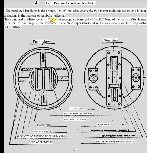
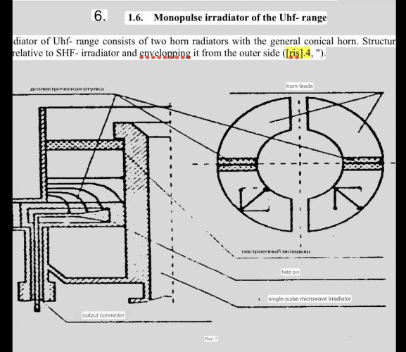
1.4. Dual-band combined irradiator
The combined irradiator is primary «point» the radiation source of the two-mirror emitting system is intended for formation of specified amplitude-phase distributions in a parabolic aperture mirrors.
The combined feed consists (Fig. 4) of a monopulse feed horn feed of the microwave wave range of the main channel, compensation feed channel and compensating devices of this range in the azimuthal plane (H-compensator) and in the elevation plane (E-compensator), as well as horn UHF irradiator with its tuning elements.
The technical solution of the combined irradiator is presented it is a compact cylindrical structure, at the front end of which it is located combined opening of feeds of different ranges and functional purposes, and on the reverse side – output waveguide adapters of the main one and compensation channels and coaxial SGO feed connectors.
Let's look at the design, main features and principle of operation individual irradiators, compensating emitters and devices.
1.5. Monopulse microwave feed
In the central part of the combined the irradiator contains a monopulse horn irradiator in the microwave range, which unlike traditional four-horn monopulse feeders, it contains two horns with a common wide wall located vertically. It became possible through the use of waveguides on higher types of waves. Such the technical solution was due to the desire to reduce the dimensions of the irradiator and simplify the design of the total-difference processing circuit for those received signals. This made it possible to combine them in one structure along with radiating ones waveguide elements for summing and subtracting microwave signals.
Figure 5 shows the projections of the horn feed and its main ones sections.
The front view shows the opening of a two-element horn an irradiator that continues with a section of waveguide ending a stepped transition in the plane of a wide wall (H-plane). In this place the waveguide path contains a double T-bridge, in which the H-arm is the total output of the irradiator, a E-shoulder – azimuthal difference output.
Between the wide walls of the waveguides of adjacent emitters the main waveguide of the elevation channel passes through, which has a slot connection with the paths of the radiating elements of the horn feed (side view Fig.5). This waveguide device is similar to a single plane T-bridge. Its work is defined by type waves excited in the opening of the horn feed. When falling waves of type H10 the opposite arms of the T-bridge are excited by antiphase signals from one level, and there is no signal at its output. When exciting waves of type H20 the level and phase of the output signal will be determined by phase relationships signals excited at its input arms.
Let's look at some of the most typical examples of work monopulse signal processing circuit that allows you to generalize its principle works.
When the electromagnetic field of horizontal polarization drops normal to the irradiator opening in the equal-signal direction (RSN) in waveguides in-phase waves of type H are excited10, which are subtracted in azimuthal and elevation outputs, where there will be no difference signals, but at total output - fold in phase.
When the electromagnetic field falls at an angle to the RSN c azimuthal plane (E-plane in Fig.5) and on the RSN in the elevation plane (H-plane in Fig.5) antiphase waves of type H are excited in the waveguides10, and a difference signal will appear at the azimuthal output, the magnitude of which will be proportional to the angle of incidence of the electromagnetic field in the E-plane, and its polarity corresponds to the direction of deviation from the RSN. At the same time on at the elevation output, the signals will be subtracted to zero, and at the total output – fold in phase.
When the field falls on the RSN in the azimuthal plane and at an angle to RSN in the elevation plane in waveguides excite waves of type H20. A difference signal will appear at the elevation output, the magnitude of which will be proportional the angle of incidence of the electromagnetic field in the H-plane, and its polarity correspond to the direction of deviation from the RSN. At the same time, at the azimuthal output the signals will be subtracted to zero, and at the total output – they will add up in phase.
In real conditions, the signals excite the horn feed under some angles in both planes at the same time and therefore at the weekend the irradiator devices constantly have proportional signals instantaneous angular position of the target in space.
The given design of the irradiator and modern technology its production made it possible to ensure decoupling between the total and difference outputs at least 20 dB.
8.6. Compensating emitters and devices
Low UBL required for effective Doppler filtering target signals in the radar are provided by the formation of a special compensation pattern forms. In the receiving mode, the level of the near and far side lobes is at the bottom the elevation section of the DN is reduced using two special ones emitters (Fig. 6): in the form of the open end of a waveguide with a dielectric filling, loaded onto a two-vibrator emitter type «wave channel» (the passive element of the compensating device, which will be discussed below) and E-sector horn, located, respectively, in a combined to the feed and outside the antenna radiating system (see Fig.2).
Signals received by these emitters are supplied to the wave divider of the distribution system (see. fig. 3).
Joint processing of signals received on the main and compensation channels are carried out in the radar receiving device.
In addition, special compensating devices located structurally in a combined irradiator, they provide a reduction the level of the first two side lobes in the elevation plane (hereinafter for for short, we will call this device E-compensator) and the first side device petal in the azimuthal plane (H-compensator) on both sides of the main one maximum DN.
E-compensator (Fig. 6) consists of two passive elements, one of which – upper - two-vibrator emitter type «wave channel» is installed in the opening of the compensation channel emitter, and the other - lower – installed in the lower part combined irradiator and has one symmetrical vibrator. Fastening these the elements provide for their rotation in a vertical plane. Location and their inclination relative to the opening of the horn feed of the main channel selected in such a way that the main maximum DN of vibrator emitters coincided with the maxima of the first and second side lobes of the main section of the DN antennas in the elevation plane in «view» mode, and their phases differed by 180 degrees.
The length, thickness of the vibrators and the distance between them, as well the angle of inclination of the entire element in the vertical plane is determined during adjustment antennas during its production. The main criterion for the quality of the setting is maximum suppression of the level of lateral radiation in the area of the first and second side petals of the DN.
The H-compensator consists of recesses at the edges of the emitter opening of the horn (see section in horizontal plane in Fig. 6), filled dielectric. The inflow of surface currents causes secondary radiation with the direction of the main maximum, determined by the geometric dimensions of the groove and fluoroplastic liners. By varying the configuration of the liner, the main maximum the radiation of such a secondary emitter is combined with the direction of the first side petal of the main DN on the corresponding side in the horizontal planes. Essentially, by selecting the phase relationships of surface waves at the edge opening, a pattern is formed with the required level of near lateral radiation.
1.6. Monopulse UHF feed
UHF irradiator consists of two horn emitters with a common conical horn. Constructively they are made in the form of two semicircles, symmetrical with respect to Microwave irradiator and those covering it from the outside (Fig. 4, 7).
This shape is caused by the desire to reduce external dimensions combined irradiator, as well as the need to combine phase centers irradiator in different ranges of its operation. This led to the fact that when excited fields in each of the emitters develop parasitic cross-polarization component.
Figure 7 shows, in cross-section, the feed distribution of the electrical component of the excitation field relative to the pin c a dielectric coating, and in the front view there are vector field diagrams radiation. Vertical parasitic components can be mutual compensated for complete symmetry of two emitters.
Full compensation of cross-polarization components this is achieved by adjusting the feed using dielectric inserts (see also Fig.4). By changing their size, total number and position in the bell emitters they achieve the maximum electrical symmetry of emitters.
To increase the directional properties of the UHF irradiator, it is installed a common conical horn made of a metal mesh with a large cell radio-transparent for microwave waves. A schematic representation of it is given in the figure of the general view of the antenna (see Fig.2).
1.7. Design and main features of reflectors surfaces
Reflective surfaces (mirrors) are designed for formation of spatial pattern of the main and compensation channels Microwave range with specified characteristics (width at half level power, lateral radiation level, etc.).
Reflective surfaces are formed by a system of two mirrors (fig. 8):
- «parabolic» a fixed mirror;
- «flat» movable mirror.
The names of the mirrors are taken from quotes due to the fact that they do not actually characterize the shape of the reflectors surfaces. So a «parabolic» mirror is a cutout from a body rotation formed by the rotation of a half-branch of a parabola turned towards the axis rotations at an angle of 50. The «flat» mirror is a notch from a cone with an apex angle of 2.50.
It should be noted, however, that the first samples of such antennas were parabolic and flat mirror configuration. In the process of development of domestic two-mirror antennas c for almost 35 years, the mirror configuration has been continuously improved with the aim of increasing radiating properties, but their traditional name has been preserved and is often found in literature. Therefore, these conventional names will be retained in this manual for ease of further presentation.
Let's consider the layout features of a two-mirror system (fig. 8). In such a system, the feed is located at the focus of the parabolic one mirrors, on the reverse side of which a flat mirror is installed. Scanning DN is carried out by rotating a flat mirror, which is slightly larger than a parabolic one. In this case, rotating the mirror by an angle α gives a deviation of the main maximum DN at an angle of 2α (, due to the well-known law of geometric optics, shown in fig. 8.
With this method of mechanical scanning completely DN distortions associated with the influence of phase errors typical for are eliminated single mirror antennas. Therefore, two-mirror antennas are distinguished by improved ones characteristics.
However, during scanning, DN distortions occur due to diffraction of the electromagnetic field at the edges of a flat mirror. With increasing the size of the mirror in relation to the wavelength, this influence decreases and at with an opening of 50λ or more, the DN is practically not distorted when scanning in large ones within.
Constructive alignment in the opening of two mirrors and elimination shading by a flat parabolic mirror is ensured by polarization by method. The essence of this method is the interaction of linearly polarized ones an electromagnetic wave with a periodic structure of parallel conductors.
The antenna in question emits (receives) vertically polarized wave. A parabolic mirror is a lattice of horizontal parallel wires, the distance between which is less λ/2. Such a mirror reflects a wave with horizontal polarization and almost completely transparent to vertically polarized waves.
A flat mirror is the same lattice of wires located at a distance of λ/4 above a solid metal surface, but rotated relative to the wires of the parabolic mirror by 45 degrees.
Parabolic mirror fixed relative to a movable flat mirror made in the form rigid structure made of glass fiber material, representing in the first approaching a truncated cone see Fig. 2). Glued to the inner surface of the cone fabric with wires stitched into it (in Fig. 9 they are shown as dark points (), arranged horizontally. The lower outer part is covered radio-absorbing tissue in order to suppress signals reflected from the earth surfaces.
A special feature of the antenna is its operation in two different bands waves, which significantly affected the design features of the flat one mirrors.
The design of a flat mirror is (Fig. 10) two-layer structure. The top layer is made of radio-transparent glass fiber material covered with fabric with stitched wires. Distance between them it is a quarter of the length of a microwave wave.
The bottom of the mirror is periodic an aluminum foil structure whose internal cavity is filled dielectric. In the opening of the slits formed by the periodic structure another, transverse, periodic structure of short conductors is located. The plane at level A-A for microwave waves will be continuous a metal surface, and the distance from it from the wires outside is flat the mirrors are λ/4, i.e. the total electrical size of the upper thickness the layer is defined by the expression λ/4, where ε – dielectric constant of the material, λ – microwave wavelength.
Whereas the electrical dimension of the thickness of the bottom layer is Λ/4, where ε – dielectric constant of the material, Λ – UHF wavelength.
Thus, the UHF wave passing through the top layer will be reflect from the lower metal layer, and microwave wave from plane A-A, where a periodic structure is located.
8.9 Formation of radiation patterns in microwave and UHF range waves
Let us consider the principle of operation of such an antenna for the reception case electromagnetic energy. Due to the considered design features of the flat mirrors it becomes clear that the operating principle is similar for waves, both microwave and UHF band.
Electromagnetic wave of vertical polarization, free propagating through the periodic structure of the parabolic mirror, it falls on a flat mirror.
Vector can be broken down into two components: np and ┴p (fig. 10).
Component np will be reflected from wires with «loss half-waves» - nfrom, while while the the component component of of the the ┴p, will spread behind the wires and will be reflected with
«half wave loss» from metal surface after a quarter period T/4, since the distance between ney and wires is equal to λ/4. Another through T/4 is this component, which let's denote ┴from,will appear on the surface of a wire periodic structure.
At this time, there is an incident wave on the surface of the mirror p will change the phase to π as time has passed T/2. Immediately reflective component nfrom it will work out with ┴from, and it forms horizontally oriented vector from.
Thus, the wave reflected from the flat mirror horizontal polarization propagates in the direction of internal polarization surfaces of a parabolic mirror, where, reflecting from horizontal wires, focuses in the antenna feed.
Requirements for the feed of a two-mirror antenna in many ways coincide with the requirements for mirror antenna feeds and therefore features determining the optimal amplitude-phase distribution in the antenna aperture not covered here.
Let's consider the shape of the resulting DNs in air viewing mode spaces. As noted above, for the purpose of compensating for signals received by the side signals the petals of the main highly directional pattern are carried out in the receiving tracts subtraction operation. To do this, the compensation channel DN must provide receiving signals in the area of angles requiring compensation. The most vulnerable the area for radar operation is the area towards the earth's surface, i.e. the first lower side lobes.
Fig. 11 shows the resulting compensation channel pattern in the vertical plane. It is formed as a result of adding signals to high ones frequency received by external compensation horn antenna and compensation feed antenna with E-compensator. Maximum reception area, as can be seen from the figure, it falls on the near side petals, on an angle of about 40.
In the horizontal plane, partial compensation is high the frequency is carried out using an H-compensator, similarly in the near region side petals on either side of the main petal.
Total difference DN state identification systems are formed by excitement two-element feed across a ring bridge, on a rigid coaxial one waveguide (see the left bottom image of the ring in Fig.4 (figure is in description of practical work № 18-4)). In this case, arms 1 and 3 are connected to to the emitters, signals corresponding to the difference are generated on arm 2, and on arm 4 – total DN.
The total channel is designed to emit a request signal and response reception, while the main maxima of the pattern in the microwave and UHF ranges coincide. The difference channel is used to compensate for signals received laterally petals of the total DN. Coaxial is used as the transmission line braided cable of the armored type. By selecting electrical lengths through two channels the specified ratios of the maximum level of the total DN and are ensured minimum – difference DN.
8.10. The main ones elements of an electromechanical system
The electromechanical system is designed to provide mechanical movement of the conical mirror of the emitting system with signals control from the UA channel along the azimuth and elevation axes in modes overview-maintenance, gyro-stabilization of the antenna by roll, as well as formation digital signals in binary code proportional to angular position conical mirror in azimuth and elevation, position of the emitting system roll and transmit them to the control, control and display channels.
Fig. 12 is a block diagram of an electromechanical a system that includes a power amplifier with protection and braking circuits; motors, feedback tachogenerators, two-way electric couplings the gearboxes consist of azimuth, elevation and roll axes, as well as photovoltaic ones and digital converters of output signals of the mirror position in azimuth and elevation angle and roll antennas.
Control voltage in the form a smoothly varying voltage proportional to the mismatch angles over three the coordinates Az, UM and Kr (by roll) come from the antenna control channel to power amplifier. It corresponds to the current radar operating mode – line by line overview of space or angular tracking of the target.
The power amplifier converts the signal mismatches in the control signals of the corresponding engines. At the same time the polarity of the signals determines the direction of rotation of the motor shaft, and duration – shaft rotation angle.
In a number of antennas, transmission of the axis rotation torque to the mirror provided by an electrical coupling controlled by appropriate signals.
To eliminate blows the moving parts of the antenna are supported by stops and limiters at the maximum scanning angles the motors are supplied with a limit command from a microswitch, spatial the position of which ensures its operation at the edge of the minus 2 sector0. The final stop of the mirror is fixed by a mechanical spring.
The gearbox provides the required gear ratio which is determined by the size of the antenna, i.e. the type of aircraft on which this antenna is installed. To reduce the level of electrical interference («spark» motor manifold) inductive filters installed.
Negative feedback along the control circuits is generated on tachogenerators. Voltage proportional to the speed of movement of the mirror along the axes of the AZ, UM and the base of the antenna along the Kr, it is supplied to the power amplifier. Reducing the pulsations of this voltage is ensured RC-by filters.
In order to eliminate parasitic self-oscillations of the mirror at the edges the sector uses a braking scheme that reduces the level of controls signals five times.
In the Kr channel, due to the greater mass of the antenna base than mirrors, a more powerful motor is used. For his normal the operation uses an additional – output stage, as well as a circuit protection along the Kr axis.
Antenna testing required the rotation angles of the mirror or antenna base are estimated from the signals generated by signal converters. Mechanical coupling of the converter with the corresponding axis is provided by an electric coupling. Electrical signal generated by the converter is proportional to the angle of rotation of the mirror. On more modern ones the antennas use digital converters.
The digital converter is designed to form a digital signal in the form of a combination of binary code proportional to the angles rotate and issue them to a specialized computer to determine errors mismatches in the angle range of 3600. It consists of three primary signal sensors and a common shaft-to-code converter.
The design of the sensor can be different, for example, from using optoelectronic elements. At the same time, as a shaper pulse signals use a photodiode illuminated by an LED through slots applied radially to a disk mounted on the actuator shaft – axis. The shaft-to-code converter converts the electrical pulses of the photodetector into fourteen-bit code.
8.11. Built-in control system
The built-in antenna monitoring system is an integral part VSK BRLS and is designed to assess the technical condition of the antenna and those included in no systems, devices, components and elements.
Three modes can be used during VSC operation:
1. Mode work with the target’s control pulse;
2. Mode work with built-in control horn;
3. Mode work with built-in noise generator.
In the first mode, the control signal arrives directly to the input of the receiving channels, bypassing the main antenna paths. In the second mode, that the control signal is received by the antenna and passes through the main elements of the monopulse signal processing circuits and then enters the receiving channels. And finally, in the third in mode, a noise generator is connected to the receiving path of the first channel, which generates noise signal required to test the sensitivity of the receiver.
VSK includes devices for generating and entering controls signals, as well as a high-frequency control device.
Fig. 13 is a block diagram of the VSC antenna.
The RF monitoring device is designed for switching control signal in the first two VSK modes. Included in this device the waveguide switch enters and Y-circulator. In Fig. 26, the chain passages there is no signal to the horn shown. The signal received by the antenna passes from the rotating transition through waveguide-slot bridges WM4-WM6 control input devices signal to the input of the receiving channels WD1-WD3.
The target control pulse in the second mode is supplied to the circuit divisions consisting of bridge connections WM1-WM2, which distributes the signal between three channels. All bridge connections are loaded with matched loads R1-R6 (see Chapter 1). Levels the signals are aligned using AT1-AT3 attenuators, and the signals are manipulated provided using modulators WP1-WP3 on the pin diodes.
The design of the modulator represents a section of waveguide, c the cavities of which are installed at a distance Λ/4 from each other by two diodes, c the bias circuits of which are connected to a control circuit. The modulator can operate in attenuator mode, when the transmitted signal is attenuated by an amount or « ≈ 2 dB or by the amount of ≈25 dB.
In the modulation mode, a manipulating voltage is applied to the diodes from the control signal generating device. The noise signal is introduced into the path the first channel through the waveguide-slot bridge WM3. The source of noise is semiconductor diode generator WD4 with a spectral component noise densities of the order of 36-37 dB.
The considered high-frequency path of the VSK antenna is considered as a composite one part of the general VSK radar system, allows you to analyze the performance status Radar in general and antennas in particular. In this case, non-working nodes can be defined and devices, including the main elements of feeder paths.
Questions for self-assessment
1. Which ones the problems are solved by an antenna as part of the radar.
2. Than the requirement for a low level of lateral radiation is determined and how this is solved antenna.
3. Name it the main systems that make up the antenna and determine their functionality appointment.
4. List it main antenna features related to monopulse signal processing.
5. Give it brief description of the design of the on-board two-mirror antenna.
6. Give it brief description of the design of the combined irradiator.
7. Give it brief description of the operating principle of a microwave wave irradiator.
8. Give it brief description of the principle of operation of compensation emitters and devices.
9. Give it brief description of the operating principle of a UHF wave irradiator.
10. Give it brief description of the design of reflective surfaces.
11. Give it brief description of the principle of DN formation.
12. List it main features of the electromechanical system.
13. List it main features of the high-frequency part of the VSK.
- Joined
- 27 December 2005
- Messages
- 18,727
- Reaction score
- 33,162
Yeah, I'll add them to the post.
Aeria Gloria
ACCESS: Secret
- Joined
- 8 February 2024
- Messages
- 372
- Reaction score
- 431
It also clarifies that the antenna is doing both transmission and reception of Parol. And that this through the dipoles in the antenna being UHF while the main radar function is in SHF. This is likely why radio and IFF needed syncing but do not affect RWR.
It also clarifies that the single radiator is doing both SHF and UHF, and the single monopulse horn does the same. Also? The UHF/IFF interrogator is MONOPULSE.
Either it’s monopulse just to perfectly overlay on top of the SHF monopulse emitter, and it doesn’t actually have 4 channels with different phases. OR by monopulse they just mean it uses a single pulse and not actually the “direction finding” processing using 4 channels. It is made to perfectly fit with the regular SHF monopulse emitter.
And even without monopulse, you would think some azimuth resolution could still be achieved. Very interesting and surprising
I am surprised it mentions the compensation channel so little.
Attachments
Шурави1983
ACCESS: Confidential
- Joined
- 12 May 2025
- Messages
- 59
- Reaction score
- 58
test
Is my file being shown?
Is my file being shown?
Last edited:
Aeria Gloria
ACCESS: Secret
- Joined
- 8 February 2024
- Messages
- 372
- Reaction score
- 431
I do not see a file in your post. I look forward to it!test
Is my file being showed?
Шурави1983
ACCESS: Confidential
- Joined
- 12 May 2025
- Messages
- 59
- Reaction score
- 58
Aeria Gloria
ACCESS: Secret
- Joined
- 8 February 2024
- Messages
- 372
- Reaction score
- 431
Fantastic material!The download expires in 3 days so rush!
Send
Encrypt and send files with a link that automatically expires to ensure your important documents don’t stay online forever.send.vis.ee
Aeria Gloria
ACCESS: Secret
- Joined
- 8 February 2024
- Messages
- 372
- Reaction score
- 431
One day I would love to have some front aspect information on KOLS. Some pilots have said it’s just a weak short ranged sensor. Many of these American who flew it without the laser unit and thus were likely not giving it the best chance.
A pilot I talked to said the TP search mode was almost always unwilling to lock targets despite showing them well. And that he and other pilots of his unit only used TP b.boy and HMS and OPT.
In addition, there is no data on its acquisition of afterburning targets.
And since it was only tested against MiG-21 and Yak-52, the numbers are pretty low.
MiG quotes up to 25 km range. This is the scale of the range bar in TP search COOP/interaction mode when using KVO radar ranging. Which would only function up to 35-40 km for fighters since it uses pursuit mode.
I guess we may never know.
In the simulator game DCS, KOLS has been modeled to hit the exact numbers we get in the manual. It has about 2x range from after burning targets and about 10 km head on or less against Mil targets. Around 14 km side aspect or less. 20 km rear aspect for mil F-15/18/14. And 1/3rd less range with ground look down or near clouds (once inside cloud cannot be detected at all).
View: https://youtu.be/l5OgqB-2AxY
I also wonder about the gain knob. How much it actually changes gain, What was pilots preferred position, but from the pilot I talked to he basically said “TP search is useless so we just set it to high for HMS brightness.”
A pilot I talked to said the TP search mode was almost always unwilling to lock targets despite showing them well. And that he and other pilots of his unit only used TP b.boy and HMS and OPT.
In addition, there is no data on its acquisition of afterburning targets.
And since it was only tested against MiG-21 and Yak-52, the numbers are pretty low.
MiG quotes up to 25 km range. This is the scale of the range bar in TP search COOP/interaction mode when using KVO radar ranging. Which would only function up to 35-40 km for fighters since it uses pursuit mode.
I guess we may never know.
In the simulator game DCS, KOLS has been modeled to hit the exact numbers we get in the manual. It has about 2x range from after burning targets and about 10 km head on or less against Mil targets. Around 14 km side aspect or less. 20 km rear aspect for mil F-15/18/14. And 1/3rd less range with ground look down or near clouds (once inside cloud cannot be detected at all).
I also wonder about the gain knob. How much it actually changes gain, What was pilots preferred position, but from the pilot I talked to he basically said “TP search is useless so we just set it to high for HMS brightness.”
Aeria Gloria
ACCESS: Secret
- Joined
- 8 February 2024
- Messages
- 372
- Reaction score
- 431
So, about a previous discussion. I am having new thoughts from reading things.
Perhaps the exact waveform in DNP isn’t illumination on at launch every single time.
What if it’s only doing its datalink + 7x track cycles, then ONLY WHEN it sends the “missile seeker activate” command is it removing the datalink phase and ADDING Illumination in its stead!
This would mean the target would only get illumination when missile was
Relatively close. Depending how western RWR would determine the launch, if they could determine it from datalink signal then this changes nothing but if it’s only looking for the pseudo Continous illumination signal this might work to delay launch warning.
Of course I’m not 100% sure, I could be wrong. But it would make sense at minimum of not turning on illumination until the seeker needs it, and just subtract the time from launch until this command fro the total 60s DNP illumination timer.
This is the case in DCS simulator at least that devs have “interpreted” the documents this way or have more proof then I. You can set target size to small and reduce the warning for targets until missile is within 12 km!
Of course, if your datalink doesn’t run out of 30s or farther then 25 km from launcher introducing a less accurate INS phase.


Attachments

Last edited:
Aeria Gloria
ACCESS: Secret
- Joined
- 8 February 2024
- Messages
- 372
- Reaction score
- 431
kizvy
Local su-30mkm enjoyer
- Joined
- 14 October 2025
- Messages
- 94
- Reaction score
- 88
Below is going to be some of my yapping, not 100% sure cause I don't understand some russian terminology completely/maybe there's some slight mistranslation.

Isn't this for detection, not necessarily to *maintain* lock? Like say you locked a target when they were outside of the notch filter, then they went into the filter after locking by changing radial speed. Wouldn't radar maintain lock?

From my rudimentary understanding, it would depend on amount of ground clutter. For this, I'm taking stuff from both the su-27 manual and mig-29 manual. From what I understand, n001 is basically a n019 just scaled up with more range.
also, below 10km, targets can be locked at "same speed" right?
Gonna copy paste my explanation from nother thread.
It has a hard notch filter (no matter what) even when hardlocking that corresponds to around 80 degrees when locking onto a target below 3 degrees.
(subsonic)

however, when looking more than 3 degrees above the horizon, it will always be able to track a target even if it has little to no radial velocity.

also within 10km, regardless of ground clutter?, lock can be achieved. Just that it may be "unstable".


tried to make this arguement once but wasn't sure if I was 100% correct in 'nother forum.
For war thunder simulator and I assume it would work similar in DCS, in order to not deal with not acquiring the target using radar due to notch angles/gates, I just use IRST ACM or HMS IRST mode because it's just a lot easier to use and you don't have to worry about notching at all. And then afterwards switch to radar lock to fire a radar missile or something.
Plus the much faster scan rate in the IRST acm modes makes it easier to use imo over the equivalent radar modes.
Aeria Gloria
ACCESS: Secret
- Joined
- 8 February 2024
- Messages
- 372
- Reaction score
- 431
No it’s also to maintain lock. You’ll see other passages saying with lock you must maintain that closure per range to keep the lock. It is also why it says to maintain cos sign of 60 kmh to maintain lock on a Pursuit/close combat mode target. Becuase it is adding 10 kmh to this 50 kmh closing speed assuming you are inside 15 km. A manual from a previous software version where this speed is 150 kmh at all ranges gives 180 kmh for 30 kmh buffer (3x the speed 3x the buffer).this for detection, not necessarily to *maintain* lock? Like say you locked a target when they were outside of the notch filter, then they went into the filter after locking
From what I understand, n001 is basically a n019 just scaled up with more range.
also, below 10km, targets can be locked at "same speed" right?
They are extremely similar, but N-001 is quite “improved” in many ways. It has smaller notch limits, can turn off Doppler filters at a lower angle (3 instead of 5 degrees), all around does things a little better. While N-001 might have no 50 kmh filter once inside 10 km for N-019 this is only available In close combat mode (which is of course limited to 10 km).
In COOP HMS mode or by default in Su-27 the IRST and radar will try to lock together when you press lock so you’ll be fine either way.I just use IRST ACM or HMS IRST mode because it's just a lot easier to use and you don't have to worry abo
Aeria Gloria
ACCESS: Secret
- Joined
- 8 February 2024
- Messages
- 372
- Reaction score
- 431
Someone is telling me that the above interpretation of the radar work during datalink mode is incorrect. That instead it is sending illumination during the datalink period. I am unsure of how it can send Continous signal while sending barker code. I will mention things as I figure them out.
Aeria Gloria
ACCESS: Secret
- Joined
- 8 February 2024
- Messages
- 372
- Reaction score
- 431
Yeah so I guess the radio correction phase and illumination are the same. It is frequency modulated to produce the barker code and can thus radio correction one missile while providing illumination for one shot earlier. This explains why manual only shows radio correction and radar tracking/illumination interleaved cycles.
Шурави1983
ACCESS: Confidential
- Joined
- 12 May 2025
- Messages
- 59
- Reaction score
- 58
Sounds weird, never heard about such thing in my reading of radar textbooks.No it’s also to maintain lock. You’ll see other passages saying with lock you must maintain that closure per range to keep the lock. It is also why it says to maintain cos sign of 60 kmh to maintain lock on a Pursuit/close combat mode target. Becuase it is adding 10 kmh to this 50 kmh closing speed assuming you are inside 15 km. A manual from a previous software version where this speed is 150 kmh at all ranges gives 180 kmh for 30 kmh buffer (3x the speed 3x the buffer).
Yep, probably because N001 has larger aperture, thus the main has a higher gain, while side lobes has lower. Thus the burn-through distance became larger.They are extremely similar, but N-001 is quite “improved” in many ways. It has smaller notch limits, can turn off Doppler filters at a lower angle (3 instead of 5 degrees), all around does things a little better. While N-001 might have no 50 kmh filter once inside 10 km for N-019 this is only available In close combat mode (which is of course limited to 10 km).
Real?Someone is telling me that the above interpretation of the radar work during datalink mode is incorrect. That instead it is sending illumination during the datalink period. I am unsure of how it can send Continous signal while sending barker code. I will mention things as I figure them out.
Aeria Gloria
ACCESS: Secret
- Joined
- 8 February 2024
- Messages
- 372
- Reaction score
- 431
Closure rate filter? That if you maintain same speed as target you might lose lock and your speed needs to be different by certain amount. F-14 radar has same issue.Sounds weird, never heard about such thing in my reading of radar textbooks.
Exactly, also partly why the radar shows a weaker X category signal on SPO-15 compared to MiG-29 where radar puts a higher strength F category signal on SPO-15. Larger dish means less side and back lobes.Yep, probably because N001 has larger aperture, thus the main has a higher gain, while side lobes has lower. Thus the burn-through distance became larger.
They are telling me yes, and that other Soviet SAMs do same thing of encoding frequency modulation into illumination cycle for sake of radio correctionReal?

Шурави1983
ACCESS: Confidential
- Joined
- 12 May 2025
- Messages
- 59
- Reaction score
- 58
Oh, you mean keep the closing rate ≠0, not keep a same rate during lock-on?Closure rate filter? That if you maintain same speed as target you might lose lock and your speed needs to be different by certain amount. F-14 radar has same issue.
That's what I talked in post # 386:They are telling me yes, and that other Soviet SAMs do same thing of encoding frequency modulation into illumination cycle for sake of radio correction
> 'The 'liter' frequency (a specified carrier frequency) is shared between search, track, illumination and radio correction command.'
So the sub-frequency (more specifically - 208/228 kHz) is added to 'liter' frequency around 10GHz(3cm wave). Anyway it's still a radio-correction command, not illumination.
Aeria Gloria
ACCESS: Secret
- Joined
- 8 February 2024
- Messages
- 372
- Reaction score
- 431
PreciselyOh, you mean keep the closing rate ≠0, not keep a same rate during lock-on?
Well yeah they have their own code. But radio correction also has to modulate frequency to transmit all the barker code commands for the data link like “target velocity vector 50 m/s left” or “target velocity 50 m/s faster.”The 'liter' frequency (a specified carrier frequency) is shared between search, track, illumination and radio correction command.'
So the sub-frequency (more specifically - 208/228 kHz) is added to 'liter' frequency around 10GHz(3cm wave). Anyway it's still a radio-correction command, not illumination.
Шурави1983
ACCESS: Confidential
- Joined
- 12 May 2025
- Messages
- 59
- Reaction score
- 58
Full name of 'ПОИСК': Проблемно-ориентируемая с изменяемой системой команд(Problem-Oriented Command with Varianble Systems?)
LukaszK
I really should change my personal text
- Joined
- 15 January 2018
- Messages
- 132
- Reaction score
- 180
I would translate this as: Problem -Oriented with variable system of commands. In other words this v relates to system of computer instructions, in computers like C-100.Full name of 'ПОИСК': Проблемно-ориентируемая с изменяемой системой команд(Problem-Oriented Command with Varianble Systems?)
But what is relation to the previous posts?
F-2
ACCESS: Top Secret
- Joined
- 22 May 2020
- Messages
- 1,113
- Reaction score
- 2,366
- Joined
- 11 February 2010
- Messages
- 1,714
- Reaction score
- 3,123
Pretty good showing of what the Mig-29sm mfd shows. Interestingly document refers to the radar as N019ME which is the export of the MiG-29S radar.

The GUI reminds me of one for Su-30KN program, guess same developer (Roosskaya Avionika)
That's very interesting, presumably this is the "second" SM upgrade, such as used by Syria and Serbia, not the "first" SM shown in the 1990s, which among others has a different MFD that could also show missile seeker imagery (about which i haven't seen anything other than a video from an air expo, no idea what the MFD is called, or better images of it)?Pretty good showing of what the Mig-29sm mfd shows. Interestingly document refers to the radar as N019ME which is the export of the MiG-29S radar.
Also interesting to see N-019ME range listed as 150km, presumably vs bomber size targets, but again, maybe this is a "newer" ME, maybe with a more modern processor (Baget?) than the Ts101?
F-2
ACCESS: Top Secret
- Joined
- 22 May 2020
- Messages
- 1,113
- Reaction score
- 2,366
I believe it’s also used by the J-11A? Possibly the low cost mfd solution for all platforms?View attachment 809351
The GUI reminds me of one for Su-30KN program, guess same developer (Roosskaya Avionika)
Aeria Gloria
ACCESS: Secret
- Joined
- 8 February 2024
- Messages
- 372
- Reaction score
- 431
If we apply radar equation to original N-019 it can indeed detect a B-52 from nearly 150 km. This must be why they gave it a front aspect radar display of 2x the range actually practical.That's very interesting, presumably this is the "second" SM upgrade, such as used by Syria and Serbia, not the "first" SM shown in the 1990s, which among others has a different MFD that could also show missile seeker imagery (about which i haven't seen anything other than a video from an air expo, no idea what the MFD is called, or better images of it)?
Also interesting to see N-019ME range listed as 150km, presumably vs bomber size targets, but again, maybe this is a "newer" ME, maybe with a more modern processor (Baget?) than the Ts101?
If N-019M got 80 km vs 3m squared and Ukrainians with MiG-29 upgrades I think have gotten basically Su-27 ranges which is 30% more powerful or so. Yet I think Zhuk is rated only to 110 km for 3m squared.
We have seen MFI-55 with same symbology on both MiG-29 and Su-27/J-11 upgraded in BelarusI believe it’s also used by the J-11A? Possibly the low cost mfd solution for all platforms?
I apologize for self plugging myself but I did this video recently on the speed limits of the N-019 radar modes, I believe they are the same for N-019M.
However manuals say notch should be “tracked through” in look up over 5 degrees and in pursuit mode at ranges of less then 10-15 km as long as altitude is not below 2,500m.
However this would make it weak to chaff, and I have seen references to chaff only affecting it when tracking people through the notch, however if B.Boy mode notched filter goes from 200 kmh to 60 kmh when antenna is over 5 degrees perhaps when manual says “can track target at 4/4 angle” in these instances it means the notch is just so much smaller (but not 0 kmh) that with radar memory mode it shouldn’t matter. Who knows, I wonder what R-27R effect by chaff would be when target cross notch.

Last edited:
Similar threads
-
-
 Phazotron Sapfir-23 and Sapfir-25 radar
- Started by overscan (PaulMM)
- Replies: 198
-
-
McDonnell-Douglas F-15 Avionics, AN/APG-63/70 radar
- Started by overscan (PaulMM)
- Replies: 112
-
 MiG-21LanceR A , B and C Avionics ...systems etc
- Started by AFlyer216
- Replies: 2