- Joined
- 25 June 2009
- Messages
- 15,517
- Reaction score
- 9,299
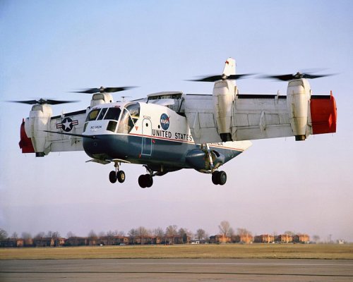
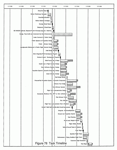
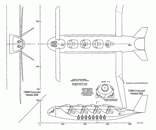
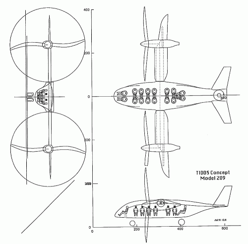
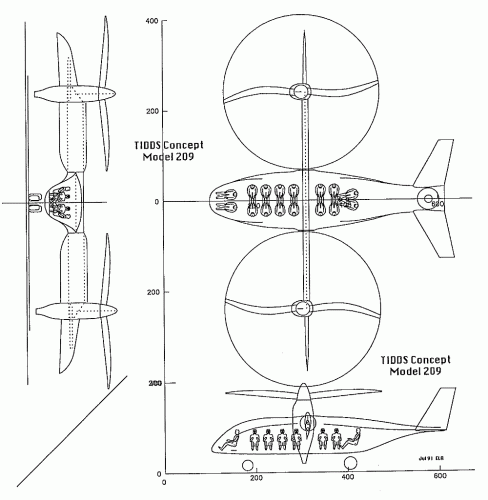
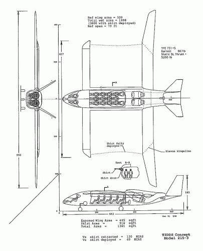
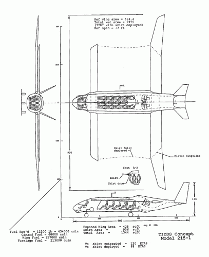
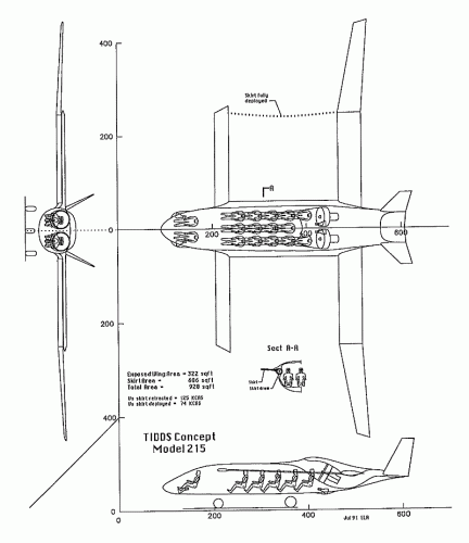
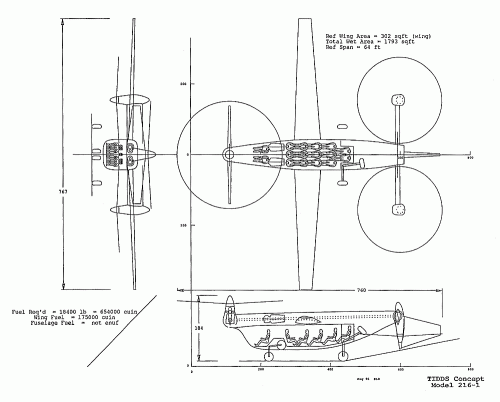
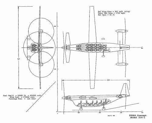
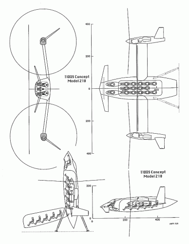
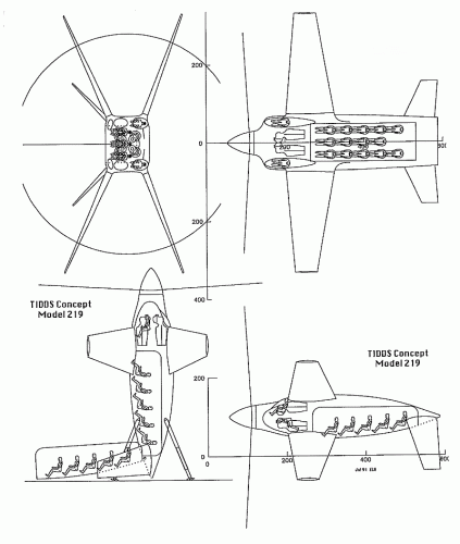
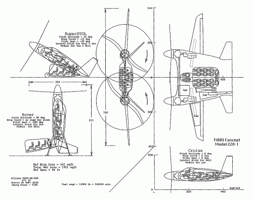
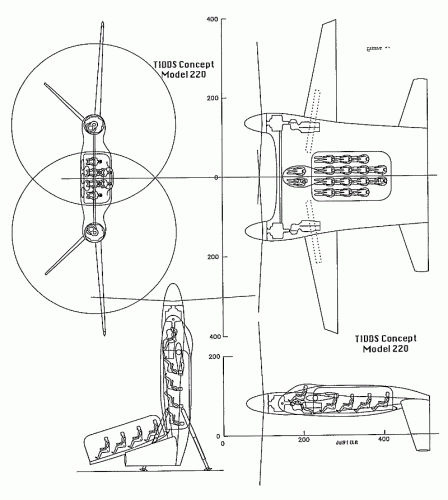
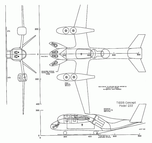
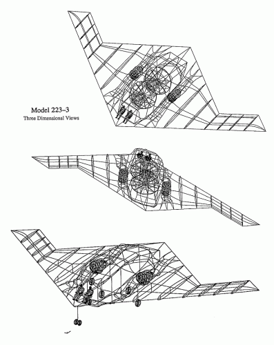
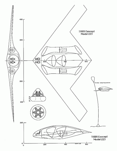
The Vought Archive at the University of Texas in Dallas contains quite a strange series of entries:
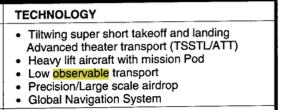
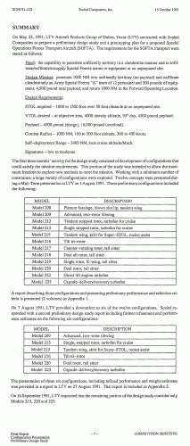
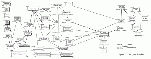
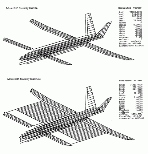
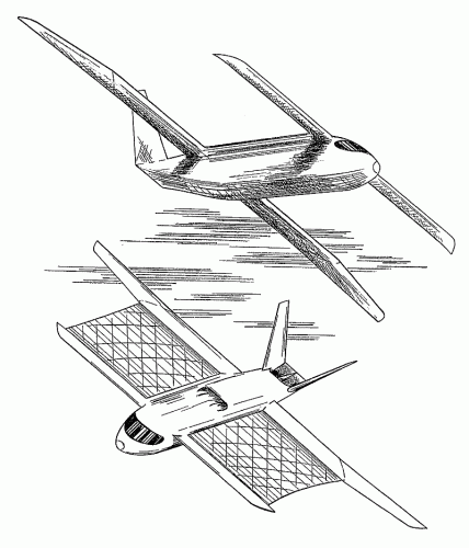
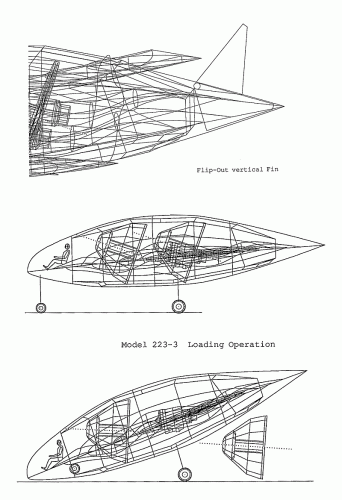
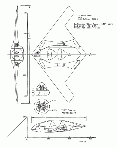
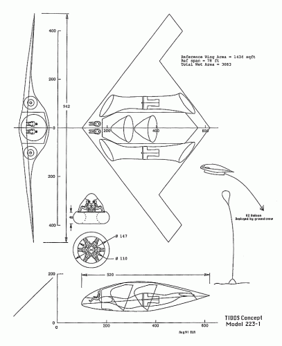
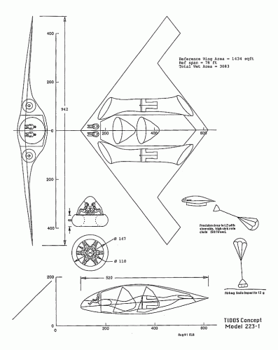
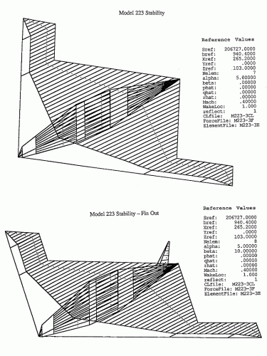
This clearly indicates that Scaled Composites conducted a study in 1991 for the rapid prototyping of a SOFTA aircraft.
Strange is the way the XC-142 seems to be associated to the same report. I first thought that the designation "XC-142" might have been a cover-up to conceal the nature of a secret SOFTA prototype built by Scaled Composites... but then why would the inhouse Scaled reports have ended up in Vought's archives?
Reversely, if the plan was to build a brand new Vought XC-142 as a SOFTA aircraft, would it have been adequate for that type of mission, and in what way could it have been a "rapid prototyping" program, knowing the size and inherent difficulties of a tilt-wing aircraft, a type of aircraft which Scaled had no previous experience of? And why go and dig up a 30-year-old design anyway?
Any thoughts would be appreciated! And if these reports are readily accessible to reviewers (as the mention "Note to the Researcher" appeared before each VAHF identification number) it would be fantastic is some forum member could go and ask to go through them!
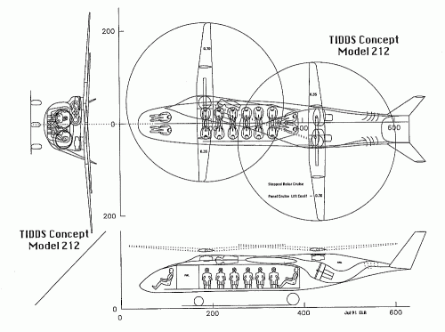
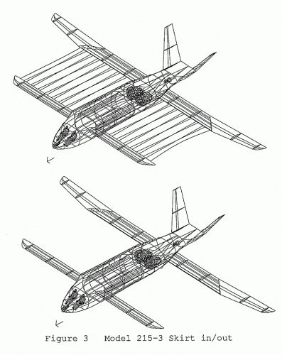
Scaled Composites Report: Special Operations Forces Transport Aircraft (SOFTA) Rapid Prototyping Plan. 1991 August 1
Design study for the XC-142 for Special Operations Forces, Volumes 1 and 2, Report No. SCIR 91-009.
Original VAHF identification number: 141-424.
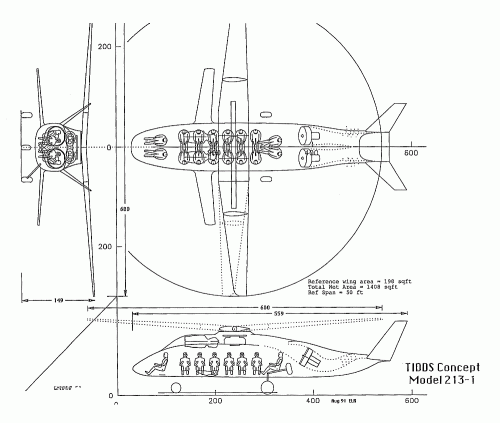
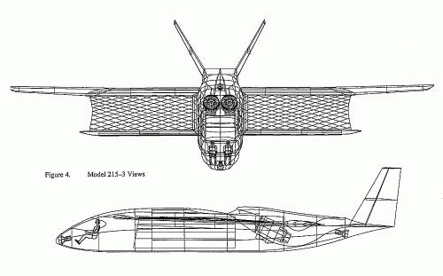
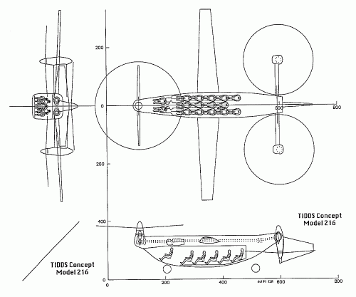
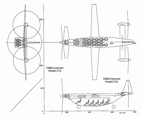
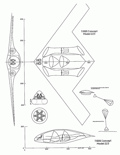
Scaled Composites Report: SOFTA Rapid Prototyping Plan. 1991 August 27
Design study for the XC-142 for Special Operations Forces, Report No. SCIR 91-010.
Original VAHF identification number: 141-423.
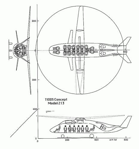
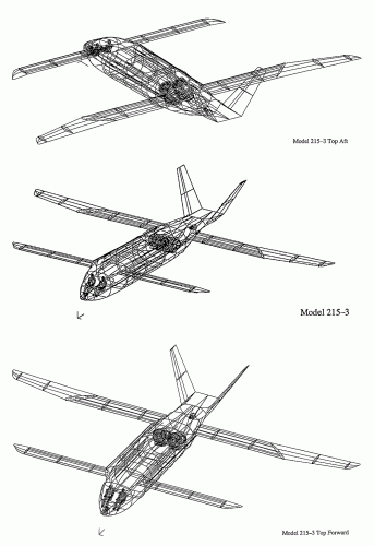
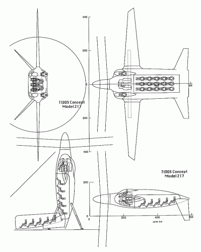
Scaled Composites Report: SOFTA Rapid Prototyping Plan. 1991 October 15
Design study for the XC-142 for Special Operations Forces, Report No. SCIR 91-012.
Original VAHF identification number: 141-425.
This clearly indicates that Scaled Composites conducted a study in 1991 for the rapid prototyping of a SOFTA aircraft.
Strange is the way the XC-142 seems to be associated to the same report. I first thought that the designation "XC-142" might have been a cover-up to conceal the nature of a secret SOFTA prototype built by Scaled Composites... but then why would the inhouse Scaled reports have ended up in Vought's archives?
Reversely, if the plan was to build a brand new Vought XC-142 as a SOFTA aircraft, would it have been adequate for that type of mission, and in what way could it have been a "rapid prototyping" program, knowing the size and inherent difficulties of a tilt-wing aircraft, a type of aircraft which Scaled had no previous experience of? And why go and dig up a 30-year-old design anyway?
Any thoughts would be appreciated! And if these reports are readily accessible to reviewers (as the mention "Note to the Researcher" appeared before each VAHF identification number) it would be fantastic is some forum member could go and ask to go through them!