
You are using an out of date browser. It may not display this or other websites correctly.
You should upgrade or use an alternative browser.
You should upgrade or use an alternative browser.
Kyushu J7W1 Shinden/J7W2 Shinden-kai

AndersJ
ACCESS: Secret
- Joined
- 7 November 2023
- Messages
- 354
- Reaction score
- 900
How about Shinden production model climb rate with three speed single stage mechanical super charger?
Did they plan to make a Shinden variant with such an engine? If so, was it any different compared to the variant I modeled or was it only the engine? In addition, do you have a chart for that engine showing the power as a function of altitude?
I totally agree, that small wings will have little effect on the maximum climp rate at low altitudes. I think, the engine didn't have it's full power at low altitude, maybe because they used a single speed supercharger for the testing which was throttled down at low altitude. This final design might have had a two?three speed or variable speed supercharging system.

Airborne2001
ACCESS: Secret
- Joined
- 19 June 2020
- Messages
- 377
- Reaction score
- 541
I have read in some replies here that the production models may have had better MK9 models for higher altitude flight. That definitely would've helped at least a little.I totally agree, that small wings will have little effect on the maximum climp rate at low altitudes. I think, the engine didn't have it's full power at low altitude, maybe because they used a single speed supercharger for the testing which was throttled down at low altitude. This final design might have had a two?three speed or variable speed supercharging system.
AndersJ
ACCESS: Secret
- Joined
- 7 November 2023
- Messages
- 354
- Reaction score
- 900
Well if any of you can provide engine data for this three speed supercharger you are talking about then I may be able to model that as well.
As it is now, I have it modeled for MIL power using this tuning data:

The power and speeds assumed are:
593km/h (266 Knots) at Sea Level - 1730hp
750km/h (405 Knots) at 8700m - 1660hp
So the current C++ simulation model is mirroring this data quite well if you compare this data to the post with simulated speed data I posted in April in this thread.
So again, with more engine power data I could model both WEP and other supercharger variants as well.
But as it is now I don't have such data.
As it is now, I have it modeled for MIL power using this tuning data:
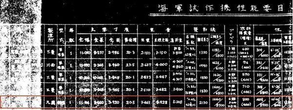
The power and speeds assumed are:
593km/h (266 Knots) at Sea Level - 1730hp
750km/h (405 Knots) at 8700m - 1660hp
So the current C++ simulation model is mirroring this data quite well if you compare this data to the post with simulated speed data I posted in April in this thread.
So again, with more engine power data I could model both WEP and other supercharger variants as well.
But as it is now I don't have such data.
AndersJ
ACCESS: Secret
- Joined
- 7 November 2023
- Messages
- 354
- Reaction score
- 900
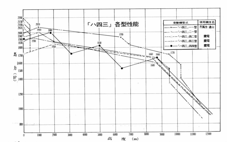
Attached is a figure which I believe shows different versions of the type of engine used in the Shinden?
I believe the dashed power curve marked with 1850 and 1660 is the one for the Ha 43 with two geared supercharger at MIL power?
However, since I can't read Japanese, the meaning of the other curves elude me. However, I do believe that two of the curves are for an engine variant with the three stage supercharger: The solid line with powers 2000 and 1830, and the upper dash dot dot dash lined curve with powers 2070 and 1930?
But this is just guesswork, and if someone proficient is Japanese can help translate the text in the figure that would be helpful.

I believe the dashed power curve marked with 1850 and 1660 is the one for the Ha 43 with two geared supercharger at MIL power?
However, since I can't read Japanese, the meaning of the other curves elude me. However, I do believe that two of the curves are for an engine variant with the three stage supercharger: The solid line with powers 2000 and 1830, and the upper dash dot dot dash lined curve with powers 2070 and 1930?
But this is just guesswork, and if someone proficient is Japanese can help translate the text in the figure that would be helpful.
AndersJ
ACCESS: Secret
- Joined
- 7 November 2023
- Messages
- 354
- Reaction score
- 900
Amazing chart!
I will traslate Japanese text in this figure into English soon.
That would be great! I'm also hoping there is some kind of information there about how long the different power settings could be utilized, e.g. if they are usable for 1, 5, 10 or 30 minutes or something like that.
Also, if there is some kind of variant information there which could tie them to the Shinden or some other Japanese planes.
Hi Anders,
Have you tried to estimate the coefficient of skin friction for the Shinden to see if the high projected speed could be considered plausible?
For benchmarking, here's a graph showing P-35, P-36A, P-40E/F, P-47D and P-51B/F with flat plat area, wetted area, and coefficient of skin fraction:
https://www.google.de/books/edition...rsus wetted area&pg=PA186&printsec=frontcover
Regards,
Henning (HoHun)
And while the Shinden's climb rate at higher altitudes and ceiling certainly were impressive, it looks like even such a standard aircraft as the P-47 D-30 matched it at higher altitudes, and even outperformed it at lower.
Certainly, it was much faster, at least as far as I have been able to gather both from Japanese estimates, and from the simulations I did in April and which is posted above, but the climb rate does not seem to have been that impressive.
Have you tried to estimate the coefficient of skin friction for the Shinden to see if the high projected speed could be considered plausible?
For benchmarking, here's a graph showing P-35, P-36A, P-40E/F, P-47D and P-51B/F with flat plat area, wetted area, and coefficient of skin fraction:
https://www.google.de/books/edition...rsus wetted area&pg=PA186&printsec=frontcover
Regards,
Henning (HoHun)
AndersJ
ACCESS: Secret
- Joined
- 7 November 2023
- Messages
- 354
- Reaction score
- 900
Hi Anders,
Have you tried to estimate the coefficient of skin friction for the Shinden to see if the high projected speed could be considered plausible?
For benchmarking, here's a graph showing P-35, P-36A, P-40E/F, P-47D and P-51B/F with flat plat area, wetted area, and coefficient of skin fraction:
https://www.google.de/books/edition...rsus wetted area&pg=PA186&printsec=frontcover
Regards,
Henning (HoHun)
Hi Henning,
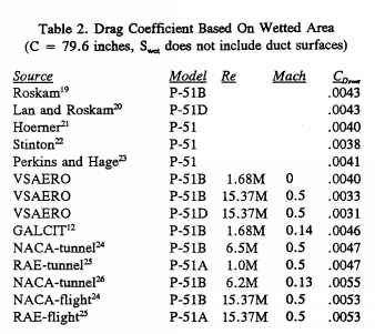
Yes, I have looked into the flat plate drag areas and to me it does seem reasonable that the Shinden has a low value compared to conventional propeller planes:
There is in fact another pusher type aircraft, the XP-55 Ascender, which also seems to have a very low flat plate drag area, about the same as the Shinden’s. And both of these are low, in the order of 5% less than on the P-51D as far as I can tell.
For the Shinden, I would say that the low drag is probably due to it being so cone shaped, which leads to a negative pressure gradient over a larger part of the fuselage which in turn means that the boundary layer build-up is slow and probably laminar on some of the forward parts. And of course, there is no propeller slipstream to trigger boundary layer transition or increase skin friction. And then when the contraction of the fuselage starts, the Shinden’s propeller sucks the boundary layer into the propeller slipstream, which goes a long way to handle the positive pressure gradient and the boundary layer build-up over the fuselage up to this point, and basically eliminates the base drag.
However, on a conventional aircraft like the P-51, the propeller slipstream leads to a turbulent boundary layer over the fuselage from the start, plus that the air’s speed over it is higher than the free-stream velocity, i.e. leading to more drag.
So on the whole, I would say it’s quite reasonable that a well-conceived pusher aircraft has a lower flat plate drag area than a tractor with roughly the same length and wing area.
Finally, can you please post a picture or write out the values from the book you referenced? I get an error message and can’t see any pages in it.
Regards,
Anders
Hi Anders,
Thanks a lot for the detailed discussion! What do you make of the quite unusual exhaust arrangement of the Shiden? If I understand it correctly, the exhausts are set up as ejectors to "pump" cooling air through the engine compartment, which probably means the Shiden doesn't get much in the way of direct exhaust thrust, which might the comparison to types like the P-51, which benefit from substantial amounts of this kind of thrust, a bit difficult.
To my dismay, I don't have access to the linked page anymore, either. I presume Google Books inherently limits the numbers of views for pages from still-copyrighted books - if I'd been aware of that before had, I'd have saved a screenshot at least. My apologies!
Regards,
Henning (HoHun)
For the Shinden, I would say that the low drag is probably due to it being so cone shaped, which leads to a negative pressure gradient over a larger part of the fuselage which in turn means that the boundary layer build-up is slow and probably laminar on some of the forward parts. And of course, there is no propeller slipstream to trigger boundary layer transition or increase skin friction. And then when the contraction of the fuselage starts, the Shinden’s propeller sucks the boundary layer into the propeller slipstream, which goes a long way to handle the positive pressure gradient and the boundary layer build-up over the fuselage up to this point, and basically eliminates the base drag.
Thanks a lot for the detailed discussion!
What do you make of the quite unusual exhaust arrangement of the Shiden? If I understand it correctly, the exhausts are set up as ejectors to "pump" cooling air through the engine compartment, which probably means the Shiden doesn't get much in the way of direct exhaust thrust, which might the comparison to types like the P-51, which benefit from substantial amounts of this kind of thrust, a bit difficult.Finally, can you please post a picture or write out the values from the book you referenced? I get an error message and can’t see any pages in it.
To my dismay, I don't have access to the linked page anymore, either. I presume Google Books inherently limits the numbers of views for pages from still-copyrighted books - if I'd been aware of that before had, I'd have saved a screenshot at least. My apologies!
Regards,
Henning (HoHun)
Seems like it had a poor fineness ratio. All that torque with a short body was probably like driving a Bronco II at the Baja. If it had a prop cowling or something to help self-orient itself via drag then it probably would have been easier to control. People assume the prototype represented the final design and I disagree. I believe they were simply proving the concept with a mind towards producibility. Pretty obvious It had some control flaws. But given time they would have decyphered the lessons.
The modern pusher Airboats were invented in 1915, so probably a good thing the Japanese didn't find inspiration from them. Both trimming and rudder control would have been something they could have engineered solutions with enough time and testing. Using thrust-driven flaps to solve some of the trim and control issues is a solution they probably never considered. But we already know they didn't enjoy the time to find solutions.
The modern pusher Airboats were invented in 1915, so probably a good thing the Japanese didn't find inspiration from them. Both trimming and rudder control would have been something they could have engineered solutions with enough time and testing. Using thrust-driven flaps to solve some of the trim and control issues is a solution they probably never considered. But we already know they didn't enjoy the time to find solutions.
Last edited:
AndersJ
ACCESS: Secret
- Joined
- 7 November 2023
- Messages
- 354
- Reaction score
- 900
Hi Anders,
Thanks a lot for the detailed discussion!
To my dismay, I don't have access to the linked page anymore, either. I presume Google Books inherently limits the numbers of views for pages from still-copyrighted books - if I'd been aware of that before had, I'd have saved a screenshot at least. My apologies!
Regards,
Henning (HoHun)
Good point about the exhaust thrust Henning, and I think I may have been a bit optimistic there since I assumed a default contribution, and with that applied then for the 750 km/h TAS to hold, then the flat plate drag area for the Shinden would have to drop in relation to the XP-55 so it would have had to be smaller. In fact, I too, was skeptical about the Shinden’s low drag, but when I reverse engineered the XP-55, I was not so sure anymore since that turned out to be so low. However, I would not be surprised if the Japanese estimates for the Shinden were optimistic, and given that no Shinden ever flew faster than 250 km/h, I guess we will never know if the Shinden would really have been as fast as projected.
About the book data: No worries, I was just curious about which numbers they had arrived at. I know you do good performance estimates yourself, and as you know, it’s impossible to distinguish if a certain speed is the result of low drag or a well working engine and propeller combination, and the important thing is just to be consistent when doing comparisons.
AndersJ
ACCESS: Secret
- Joined
- 7 November 2023
- Messages
- 354
- Reaction score
- 900
Seems like it had a poor fineness ratio. All that torque with a short body was probably like driving a Bronco II at the Baja. If it had a cowling or something to help self-orient itself via drag then it probably would have been easier to control.
For sure, and based on what I heard about the only 3 test flights totaling 45 min and going no faster than 250 km/h IIRC, there was even so a lot of issues to iron out before they could have taken it to high speed and hard maneuvering trials.

blackkite
Don't laugh, don't cry, don't even curse, but.....
- Joined
- 31 May 2007
- Messages
- 9,515
- Reaction score
- 9,652
Ha43type11:single stage two speed mechanical supercharger+turbo charger
Ha43type42 and 43:single stage single speed mechanical super charger+vulkan coupling drive supercharger
Ha43type44:single stage three speed mechanical supercharger only
Ha43type42 and 43:single stage single speed mechanical super charger+vulkan coupling drive supercharger
Ha43type44:single stage three speed mechanical supercharger only
Last edited:
AndersJ
ACCESS: Secret
- Joined
- 7 November 2023
- Messages
- 354
- Reaction score
- 900
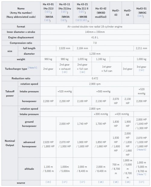
Yes, and apparently there is also a Ha43-51 three speed variant which is the uppermost power curve in the engine power versus altitude chart I posted earlier. And when you cross-reference that chart to the table below (which I translated from Japanese Wikipedia), we can by comparing the power values conclude that the solid line and the dash-dot-dot lines are for the three speed superchargers.
However, does anyone have any information if any of those (the Ha43-44 and/or Ha43-51) were slated to be built into later Shindens? And if so, where can we find information about this?

However, does anyone have any information if any of those (the Ha43-44 and/or Ha43-51) were slated to be built into later Shindens? And if so, where can we find information about this?
AndersJ
ACCESS: Secret
- Joined
- 7 November 2023
- Messages
- 354
- Reaction score
- 900
@HoHun : I have adjusted both the Cdo and the exhaust thrust for the J7W1 in my C++ model and now get about 745 km/h top speed.
In addition, I realize now that the figures I gave you earlier about the flat plate drag area relationship between the Shinden and the Mustang were the low Mach values, and if I go in and look what I get for the Mustang (assuming about 730 km/h in top speed) in my C++ model which accounts for drag creep due to compressibility effects, I see that at these speeds the Shinden's flat plate drag area is actually 11% higher than the Mustang's. Note that the Mustang's values are for M=0.65 and the Shinden's for M=0.68 due to the different altitudes they attain max speed at.
In addition, I realize now that the figures I gave you earlier about the flat plate drag area relationship between the Shinden and the Mustang were the low Mach values, and if I go in and look what I get for the Mustang (assuming about 730 km/h in top speed) in my C++ model which accounts for drag creep due to compressibility effects, I see that at these speeds the Shinden's flat plate drag area is actually 11% higher than the Mustang's. Note that the Mustang's values are for M=0.65 and the Shinden's for M=0.68 due to the different altitudes they attain max speed at.
Hi Anders,
The bright thing about the ejector cooling exhausts is that they cut down on cooling drag. I believe NACA RM No. E6L13a "Flight Comparison of Performance and Cooling Characteristics of Exhaust-Ejector Installation with Exhaust-Collector-Ring Installation", showing the use of the exhaust gases to draw air through the cooler, talks about that:
https://ntrs.nasa.gov/citations/20030063220
Interesting that the Mach influence increases the Shinden's drag so much!
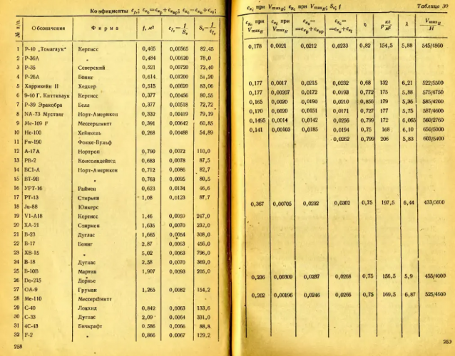
The Google Books link above works again now, so here some numbers, roughly read off the diagram:
P-35, P-40E/F, P-47D: cf = 0.005
P-36A: cf = 0.0044
P-51B: cf = 0.0042
P-51F: cf = 0.0038
Wetted areas (logarithmic scale in the diagram, so I can't make great claims to the accuracy of my readings):
P-35: 7.5 * 10^2 sqft
P-36A, P-40E/F: 8 * 10^2 sqft
P-51B/F: 8.8 * 10^2 sqft
P-47D: 1.02 * 10^3 sqft
Regards,
Henning (HoHun)
@HoHun : I have adjusted both the Cdo and the exhaust thrust for the J7W1 in my C++ model and now get about 745 km/h top speed.
In addition, I realize now that the figures I gave you earlier about the flat plate drag area relationship between the Shinden and the Mustang were the low Mach values, and if I go in and look what I get for the Mustang (assuming about 730 km/h in top speed) in my C++ model which accounts for drag creep due to compressibility effects, I see that at these speeds the Shinden's flat plate drag area is actually 11% higher than the Mustang's. Note that the Mustang's values are for M=0.65 and the Shinden's for M=0.68 due to the different altitudes they attain max speed.
The bright thing about the ejector cooling exhausts is that they cut down on cooling drag. I believe NACA RM No. E6L13a "Flight Comparison of Performance and Cooling Characteristics of Exhaust-Ejector Installation with Exhaust-Collector-Ring Installation", showing the use of the exhaust gases to draw air through the cooler, talks about that:
https://ntrs.nasa.gov/citations/20030063220
Interesting that the Mach influence increases the Shinden's drag so much!
The Google Books link above works again now, so here some numbers, roughly read off the diagram:
P-35, P-40E/F, P-47D: cf = 0.005
P-36A: cf = 0.0044
P-51B: cf = 0.0042
P-51F: cf = 0.0038
Wetted areas (logarithmic scale in the diagram, so I can't make great claims to the accuracy of my readings):
P-35: 7.5 * 10^2 sqft
P-36A, P-40E/F: 8 * 10^2 sqft
P-51B/F: 8.8 * 10^2 sqft
P-47D: 1.02 * 10^3 sqft
Regards,
Henning (HoHun)
AndersJ
ACCESS: Secret
- Joined
- 7 November 2023
- Messages
- 354
- Reaction score
- 900
Hi Anders,
The bright thing about the ejector cooling exhausts is that they cut down on cooling drag. I believe NACA RM No. E6L13a "Flight Comparison of Performance and Cooling Characteristics of Exhaust-Ejector Installation with Exhaust-Collector-Ring Installation", showing the use of the exhaust gases to draw air through the cooler, talks about that:
https://ntrs.nasa.gov/citations/20030063220
Interesting that the Mach influence increases the Shinden's drag so much!
The Google Books link above works again now, so here some numbers, roughly read off the diagram:
P-35, P-40E/F, P-47D: cf = 0.005
P-36A: cf = 0.0044
P-51B: cf = 0.0042
P-51F: cf = 0.0038
Wetted areas (logarithmic scale in the diagram, so I can't make great claims to the accuracy of my readings):
P-35: 7.5 * 10^2 sqft
P-36A, P-40E/F: 8 * 10^2 sqft
P-51B/F: 8.8 * 10^2 sqft
P-47D: 1.02 * 10^3 sqft
Regards,
Henning (HoHun)
Interesting report Henning, thanks for linking. And that there is an ejector function like that makes sense since in order to generate 50-60 kp of exhaust thrust like on the DB 605 at St & Kampf L for example, you need to move a lot of air. And in a suitable duct that will increase the thrust also (e.g like on the AJ 37 and JA 37 Viggen), and in the case of the Shinden decrease the cooling drag.
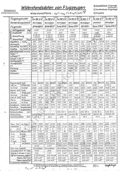
About flat plate drag areas, to add to those you listed, Americas 100 thousand by F Dean, gives 4.1 sqr ft for the P-51D, 5.71 sqr ft for the P-40 and 6.39 sqr ft for the P-47B.

- Joined
- 8 March 2009
- Messages
- 1,169
- Reaction score
- 1,733
4-7% more drag for anything in propwash is a figure I've seen.However, on a conventional aircraft like the P-51, the propeller slipstream leads to a turbulent boundary layer over the fuselage from the start, plus that the air’s speed over it is higher than the free-stream velocity, i.e. leading to more drag.
Regards,
Anders
Wetted areas (logarithmic scale in the diagram, so I can't make great claims to the accuracy of my readings):
P-35: 7.5 * 10^2 sqft
P-36A, P-40E/F: 8 * 10^2 sqft
P-51B/F: 8.8 * 10^2 sqft
P-47D: 1.02 * 10^3 sqft
Regards,
Henning (HoHun)
P-63C | | 914.6 |
F8F-2 | | 891.8 |
P-51B | | 874 |
P-51D | | 882.2 |
Spit IX | | 831.2 |
P-329N | | 773.1 |
Fw-190D-9 | | 761.6 |
Fw-190A-8 | | 735 |
Me-209 V4 | | 468.7 |
FW-190 V1 | | 594 |
F8F-2 | | 877.6 |
BF 109F | | 639 |
He-100D | | 559.3 |
Again, a vulcan coupling is a coupling made out of vulcanized rubber. Such a coupling might have been usefull for the long driveshaft. But here, for thecsupercharger a Voitinger hydraulic coupling with variable filling would have been the much more likely choise (German style).Ha43type11:single stage two speed mechanical supercharger+turbo charger
Ha43type42 and 43:single stage two speed mechanical super charger+vulkan coupling drive supercharger
Ha43type44:single stage three speed mechanical supercharger only
- Joined
- 8 March 2009
- Messages
- 1,169
- Reaction score
- 1,733
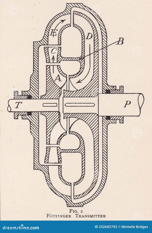
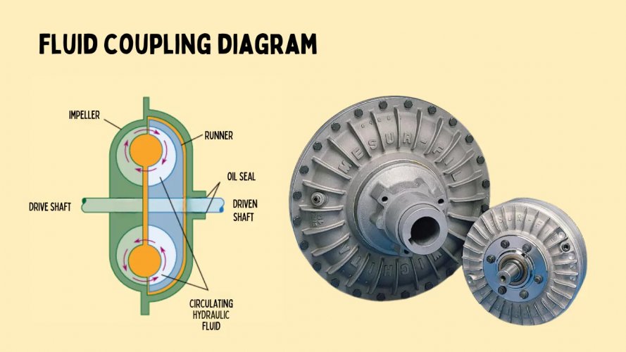
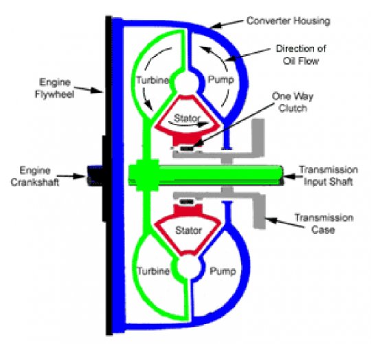
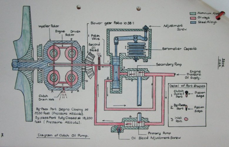
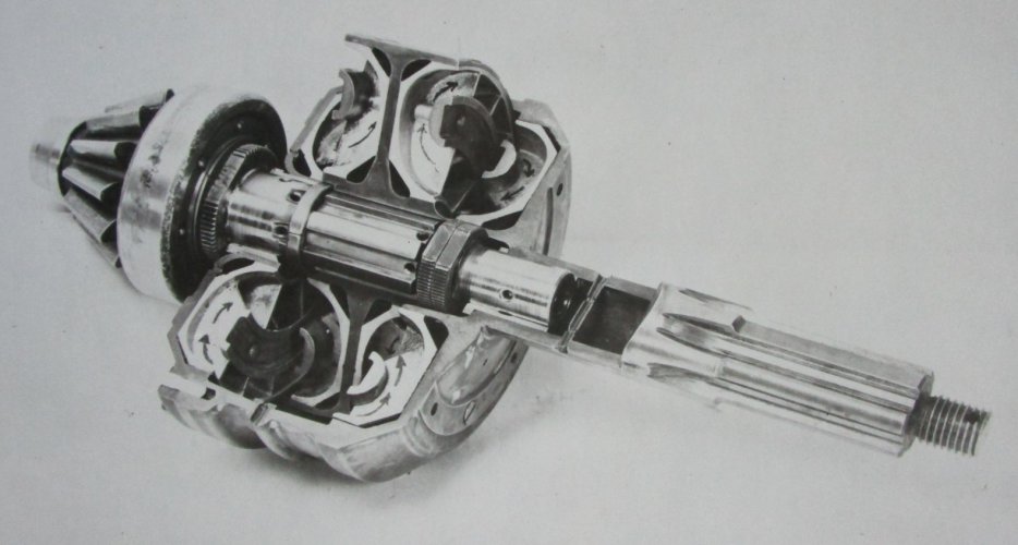
Note some of them are couplings and some are torque converters. The first exampe e.g ''Foetinger transmitter'' is a torque converter with a guiding wheel. The 2nd, 4th and 5th exampels are Foetinger couplingsHi! Fluid coupling.

- Joined
- 11 March 2006
- Messages
- 8,537
- Reaction score
- 4,998
The discussion about the Vulkan/Foettinger coupling was moved to a separate topic here
https://www.secretprojects.co.uk/threads/vulkan-or-foettinger-coupling.50248/
https://www.secretprojects.co.uk/threads/vulkan-or-foettinger-coupling.50248/
blackkite
Don't laugh, don't cry, don't even curse, but.....
- Joined
- 31 May 2007
- Messages
- 9,515
- Reaction score
- 9,652
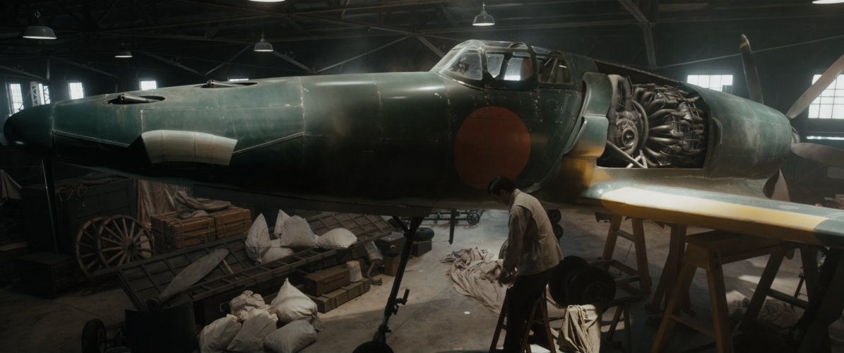
Attachments
Last edited:
blackkite
Don't laugh, don't cry, don't even curse, but.....
- Joined
- 31 May 2007
- Messages
- 9,515
- Reaction score
- 9,652
blackkite
Don't laugh, don't cry, don't even curse, but.....
- Joined
- 31 May 2007
- Messages
- 9,515
- Reaction score
- 9,652
AndersJ
ACCESS: Secret
- Joined
- 7 November 2023
- Messages
- 354
- Reaction score
- 900
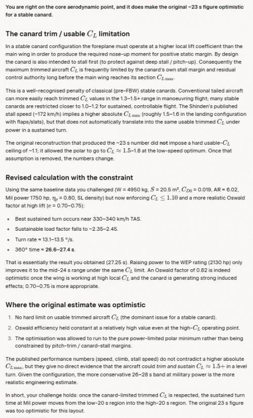
In the WW2Aircraft.net forum, the Shinden's turn performance came up for discussion, and while the J7W1 probably would have been a formidable interceptor, it would most likely not have been a very good dogfighter, since its turn performance would most likely have been quite poor.
Initially however, Grok came back with a rather optimistic estimate for the Shinden's turn time, but when challenged, conceded that the J7W1's trimmed Clmax would probably not be that stellar, but more in line with an estimate of around 1.1 as detailed in an earlier post in this thread.
Grok's revised turn rate estimate:

Initially however, Grok came back with a rather optimistic estimate for the Shinden's turn time, but when challenged, conceded that the J7W1's trimmed Clmax would probably not be that stellar, but more in line with an estimate of around 1.1 as detailed in an earlier post in this thread.
Grok's revised turn rate estimate:
Airborne2001
ACCESS: Secret
- Joined
- 19 June 2020
- Messages
- 377
- Reaction score
- 541
It feels like the Shinden would've been a pure Boom-N-Zoom fighter. A pilot flying the plane would've needed to use its speed to fight primarily over turning. So basically, think of Fw-190s or P-47s. However, the J7W appears to have had higher wing loading than even those types (though it would depend on weapon and fuel loads). One benefit that the japanese would've had is that the J7W being an interceptor means that high fuel loads weren't as big of a priority. In a theoretical encounter with the P-47N and P-82 an experienced pilot behind the J7W could do pretty well, though with a P-51D and especially a P-51H the challenge goes up a bit.In the WW2Aircraft.net forum, the Shinden's turn performance came up for discussion, and while the J7W1 probably would have been a formidable interceptor, it would most likely not have been a very good dogfighter, since its turn performance would most likely have been quite poor.
AndersJ
ACCESS: Secret
- Joined
- 7 November 2023
- Messages
- 354
- Reaction score
- 900
It feels like the Shinden would've been a pure Boom-N-Zoom fighter. A pilot flying the plane would've needed to use its speed to fight primarily over turning. So basically, think of Fw-190s or P-47s. However, the J7W appears to have had higher wing loading than even those types (though it would depend on weapon and fuel loads). One benefit that the japanese would've had is that the J7W being an interceptor means that high fuel loads weren't as big of a priority. In a theoretical encounter with the P-47N and P-82 an experienced pilot behind the J7W could do pretty well, though with a P-51D and especially a P-51H the challenge goes up a bit.
Yes, that's my take as well: I think the Shinden was designed as an interceptor, not a dogfighter and it probably would have excelled at the former since it was both fast and had reasonably good climb. But the big win with the pusher design was in armament I think: The concentration of four 30 mm cannon close together in the nose would have provided a devasting punch even in a high speed pass with short time on target. And I suspect that that was the idea: To be able to make decisive hits on a B-29 and then zoom back up again for another pass. However, when facing other fighters, I think a J7W1 pilot would be wise to avoid dogfighting any US fighters, since it would have been out-turned even by a P-47 Thunderbolt!
Scott Kenny
ACCESS: USAP
- Joined
- 15 May 2023
- Messages
- 19,511
- Reaction score
- 27,957
The best advantage of that is there's no focus cone of fire like with wing guns. The nose guns all fire more or less parallel to each other and give you a much longer effective range than wing guns do.But the big win with the pusher design was in armament I think: The concentration of four 30 mm cannon close together in the nose would have provided a devasting punch even in a high speed pass with short time on target.
The US saw this with P-38s, which were able to get hits on planes at many times the range a P-47 or P-51 could.
AndersJ
ACCESS: Secret
- Joined
- 7 November 2023
- Messages
- 354
- Reaction score
- 900
Exactly. And even in flight sims, you get an idea of how good it is with the cannon in the nose if you fly the Bf 109 with the Mg151 20 mm cannon. Even if it's just one cannon, it's devastating in close because you basically hit with every shell you fire. In addition, in a dogfight deflection shot, you only have to pull enough lead and fire, and then let your opponent fly through the stream of shell irrespective of range. And then there is the advantage for long range shots just as you mentioned. In addition, it's bolted to the engine making it a tac driver. And I think this is why the Germans went went to all that trouble to have an engine cannon: Because it really is the best place for your armament.The best advantage of that is there's no focus cone of fire like with wing guns. The nose guns all fire more or less parallel to each other and give you a much longer effective range than wing guns do.
The US saw this with P-38s, which were able to get hits on planes at many times the range a P-47 or P-51 could.
Hi Anders,
Here's an older post with a quote from a USAAF P-38 pilot who also pointed out the advantages of centreline armament:
https://www.secretprojects.co.uk/th...52-projects-variants.3603/page-10#post-656219
Regards,
Henning (HoHun)
Exactly. And even in flight sims, you get an idea of how good it is with the cannon in the nose if you fly the Bf 109 with the Mg151 20 mm cannon. Even if it's just one cannon, it's devastating in close because you basically hit with every shell you fire. In addition, in a dogfight deflection shot, you only have to pull enough lead and fire, and then let your opponent fly through the stream of shell irrespective of range. And then there is the advantage for long range shots just as you mentioned. In addition, it's bolted to the engine making it a tac driver. And I think this is why the Germans went went to all that trouble to have an engine cannon: Because it really is the best place for your armament.
Here's an older post with a quote from a USAAF P-38 pilot who also pointed out the advantages of centreline armament:
https://www.secretprojects.co.uk/th...52-projects-variants.3603/page-10#post-656219
Regards,
Henning (HoHun)
Similar threads
-
-
Japanese jet transports and bombers in 1940s?
- Started by Norse
- Replies: 24
-
 Yokosuka (Yokosho/Yosho, Kugisho/Kusho) related topics on this forum
- Started by Stargazer
- Replies: 0
-
 IJN Specification 12-Shi (E12/E13, Reconnaissance Seaplane, 1937)
- Started by blackkite
- Replies: 25
-
