
You are using an out of date browser. It may not display this or other websites correctly.
You should upgrade or use an alternative browser.
You should upgrade or use an alternative browser.
Kawasaki Ki-64 ("Rob") Experimental Heavy Fighter
- Thread starter Justo Miranda
- Start date
blackkite
Don't laugh, don't cry, don't even curse, but.....
- Joined
- 31 May 2007
- Messages
- 8,821
- Reaction score
- 7,721
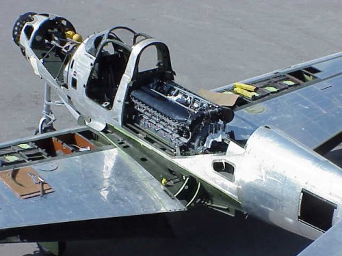
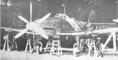
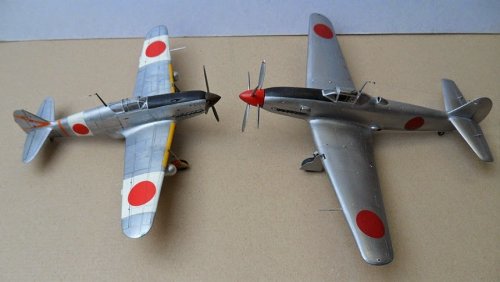
Beautiful! She had skin coolers located outer part of the laminar flow wing. Engines were two modified DB601A.
The chief designer was Takeo Doi(土井武夫,Ki-61 designer) . Skin coolers were designed under the instruction of Heinkel engineer, who came to Japan with He-119 which imported by the IJN.
The chief designer was Takeo Doi(土井武夫,Ki-61 designer) . Skin coolers were designed under the instruction of Heinkel engineer, who came to Japan with He-119 which imported by the IJN.
windswords
ACCESS: Secret
- Joined
- 19 May 2009
- Messages
- 389
- Reaction score
- 218
- Joined
- 1 May 2007
- Messages
- 2,597
- Reaction score
- 1,966
The images 'escanear 12' and 'escanear 13' are from
'Kawasaki's steam-cooled Ki-64 fighter', 'Air International' February 1978, pp.77-80.
There's little further information in the article, but I would hazard a guess that the
underwing duct housed the oil and supercharger coolers for the engines, and the
external elevator hinges incorporated mass balances.
cheers,
Robin.
windswords
ACCESS: Secret
- Joined
- 19 May 2009
- Messages
- 389
- Reaction score
- 218
Not to high jack this thread but according to a source I got from the web the Kawasaki Ki-88 was a simpler derivative of the Ki-64, with the nose engine and the vulnerable surface cooling system removed. It was never built. Does anyone have any official or unofficial drawings of this bird?
Pepe Rezende
ACCESS: Confidential
- Joined
- 3 May 2006
- Messages
- 101
- Reaction score
- 14
Grey Havoc said:I think the armor and gun deletions were field modifications by a few squadrons tasked with intercepting aircraft at higher altitudes.
As I know, this was standard use by Soviet pilots. Remember, they use less firepower than allied pilots and prefer more agile planes. I read a Soviet Airacobra ace interview and, in it's opinion, the lightened P-39 was superior to BF109F planes. I'll look for it to get the right link.
Pepe
blackkite
Don't laugh, don't cry, don't even curse, but.....
- Joined
- 31 May 2007
- Messages
- 8,821
- Reaction score
- 7,721
Oh! Only Russian pilots knew how to use P-39. I think German's fuel quality was very low same as Japanese one at the day, this is one of the reason why P-39 could fight with BF109F. But also I think it's very difficult to use P-39's low initial speed, not straight trajectory 37mm canon against fighters. Russian P-39 drivers had good skill. Honestly speaking, I like P-39. Japan could not built such a complicated aircraft at the day.
blackkite
Don't laugh, don't cry, don't even curse, but.....
- Joined
- 31 May 2007
- Messages
- 8,821
- Reaction score
- 7,721
blackkite said:I think German's fuel quality was very low same as Japanese one at the day, this is one of the reason why P-39 could fight with BF109F.
German fuel quality, while not up to fuel standards set by the Allies, was better than the Japanese's. Going from memory(thus, I might be wrong), the Germans started using 87-octane fuel in large quantities in the 1938-39 time frame, while the Japanese never managed to do that.
Pepe Rezende
ACCESS: Confidential
- Joined
- 3 May 2006
- Messages
- 101
- Reaction score
- 14
blackkite said:Oh! Only Russian pilots knew how to use P-39. I think German's fuel quality was very low same as Japanese one at the day, this is one of the reason why P-39 could fight with BF109F. But also I think it's very difficult to use P-39's low initial speed, not straight trajectory 37mm canon against fighters. Russian P-39 drivers had good skill. Honestly speaking, I like P-39. Japan could not built such a complicated aircraft at the day.
Believe it or not, Soviet aces said the P-39 turned better than BF-109s. By the way, Rob was very complex and was a sucessfull design according to Japanese sources. It's Achilles heel was the cooling system. It was projected a new one with traditional radiators for the series aircraft.
Pepe
Pepe Rezende
ACCESS: Confidential
- Joined
- 3 May 2006
- Messages
- 101
- Reaction score
- 14
Everytime you join an untried engine, with a new airframe and inexperienced pilots you will get a tragedy, but remember that a large part of the Hiens were destroyed at the ground. In my opinion, IJAAF must retain Hiens at Japan for a longer time until they were mature to combat. Another point is the Ha-40. It was lighter than DB601 and they lost reliability in the process to enhance a very complex plant and adapt it to Japanese construction methods. At Ki.64 the plant was mature enough to be used.blackkite said:Hi! Please remember the tragedy of Ki-61 at the southern front.
Cheers
Pepe
blackkite
Don't laugh, don't cry, don't even curse, but.....
- Joined
- 31 May 2007
- Messages
- 8,821
- Reaction score
- 7,721
Hi!
In 25th of April 1943, 13 Hiens tried to fly from Truk Islant to Rabaul, 2 fell, 8 made emergency landing, 2 returned and only 1 arrived to Rabaul.
In 16th of May 1943, 38 Hiens tried to fly from Japan to New Guinea, only 7 arrived to New Guinea.
In 25th of April 1943, 13 Hiens tried to fly from Truk Islant to Rabaul, 2 fell, 8 made emergency landing, 2 returned and only 1 arrived to Rabaul.
In 16th of May 1943, 38 Hiens tried to fly from Japan to New Guinea, only 7 arrived to New Guinea.
Pepe Rezende
ACCESS: Confidential
- Joined
- 3 May 2006
- Messages
- 101
- Reaction score
- 14
You only reinforced what I say above... Untried engine in an untried airframe piloted by inexperienced people...blackkite said:Hi!
In 25th of April 1943, 13 Hiens tried to fly from Truk Islant to Rabaul, 2 fell, 8 made emergency landing, 2 returned and only 1 arrived to Rabaul.
In 16th of May 1943, 38 Hiens tried to fly from Japan to New Guinea, only 7 arrived to New Guinea.
Cheers
Pepe
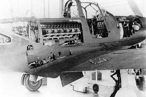
I hope I'm not wandering too far off topic with this, but since the Ki-64's Kawasaki Ha-201 engine was actually two tandem-mounted Ha-40's, which was the Ki-61 engine, I think not: Noting blackkite's loss statistics during Ki-61 deployment, if we are not to attribute this to navigational deficiencies of Japanese Army pilots, then there must have been serious reliability problems with the airplane, most likely its powerplant. Difficulties with the Kawasaki Ha-40, which was based on the Daimler-Benz DB 601A, have been mentioned in Green's Famous Fighters of the Second World War and Francillon's Japanese Aircraft of the Pacific War.
With regard to the preceding, a possible explanation was offered by Cook Cleland, who gained fame as a racing pilot after WW II. Cleland was interviewed by Jay Miller for the Vol. 1, No. 2 issue of the long dufunct magazine Aerophile. In the interview Cleland mentions that he spent the last year of the war at Pax River, Maryland, in its Tactical Test section flying Zeros, Tonys, and Kates. (For those too young to remember, "Tony" was the Allied codename for the Ki-61 Hien.) After his third dead-stick landing in the Ki-61 due to an engine seizure, he allowed the maintenance chief to disassemble the engine. Previously they had just replaced it with one from a stock of captured engines. According to Cleland the propeller on the Ki-61 was a license-built version of a Hamilton Standard type. To get it to work with the DB-601 design, the sense-of-rotation of the crankshaft had to be reversed. In doing so Kawasaki neglected to reverse splash cups on the big ends of the connecting rods which lubricated the cylinder walls. This was critical at high power settings of the engine. After the cups were cut off and rewelded in the reverse position, the engine "ran like a sewing machine".
While this sounds like a logical explanation, I have several difficulties with it. First, why was the Ha-40's crankshaft rotation reversed from that of the DB-601A? The Ha-40 is mounted in the Ki-61 airframe in the same sense as the DB is mounted in the Bf-109, as an inverted V. The propellers of both airplanes rotate in a clockwise sense as viewed by the pilot. Was a gear introduced or deleted which would have changed the engine-to-prop rotation relationship? Second, Cleland says the connecting rods couldn't simply be turned around. Was one rod on each crank throw a forked rod? Third, in an inverted-V engine, the crankcase is not also an oil sump, so what did these "splash cups" dip into? As there probably aren't many Ha-40 engines in existence will we ever really know?
Pepe Rezende
ACCESS: Confidential
- Joined
- 3 May 2006
- Messages
- 101
- Reaction score
- 14
http://www.aeroplanemonthly.com/news/news-archive/188-kawasaki-progressing-in-oz-
The HA-40 was not an exact DB601 copy. It was lightened and more powerful. In all my researchs I didn't found what changes were made by Kawasaki. One strange think is that Atsuta engines didn't seem to be ureliable.
Pepe
The HA-40 was not an exact DB601 copy. It was lightened and more powerful. In all my researchs I didn't found what changes were made by Kawasaki. One strange think is that Atsuta engines didn't seem to be ureliable.
Pepe
blackkite
Don't laugh, don't cry, don't even curse, but.....
- Joined
- 31 May 2007
- Messages
- 8,821
- Reaction score
- 7,721
Hi! I can't find such a description in my books.JimK said:In doing so Kawasaki neglected to reverse splash cups on the big ends of the connecting rods which lubricated the cylinder walls. This was critical at high power settings of the engine. After the cups were cut off and rewelded in the reverse position, the engine "ran like a sewing machine".
HA40 engine had crank shaft strength problems, because the IJA did not allow Kawasaki to use nickel, heat treatment was not proper and shaft surface hardness was insufficient. Sometimes shaft broke.
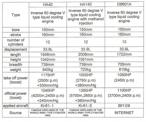
The tolerance of roller bearing surface was 10 times larger than original DB601A, because DB601A's roller bearing was made by machine and HA40's one was made by Japanese young women. Roller bearing often stuck. Fuel injection nozzle was hard to make by Japanese machine at the day. Sometimes water leak occurred at the radiator. Oil leak were common problem for Japanese engines. If only HA44 worked well, Hien was a good fighter. It's dive speed limit was 850km/h while Zero's was 650km/h. High altitude performance was good. In Japan there were enough HA40 parts, many maintenance men compared with southern front, Hien's rate of operation was good. Hien worked well as the interceptor. Over 160 B-29s were shot down by Hien.
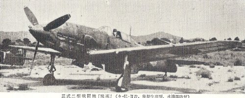
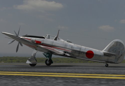
HA140 was a power up version of HA40 for Ki-61-Ⅱ, But reliability was worse. The IJA gave up to use HA140. Ki-61-Ⅱwere converted into Ki-100.There was a skin cooler experimental version of Hien, maximum speed increased 40km/h, but maintenance was hard. Hien(飛燕) means flying swallow.Designer was Takeo Doi.(土井武夫)There was a Hien pilot who overed 1,000km/h in dive, because Hien's speed meter limit was 1,000km/h and the pointer on the scales went off scale. He reported that he experienced transonic event. There were no damage on Hien.
Source:My No.2 bible and internet.
Attachments
-
 doitakeo.jpg6.6 KB · Views: 1,078
 -
 Ki-100-1.jpg35.5 KB · Views: 203
 -
 Ki100-1 initial model.jpg78.7 KB · Views: 190
 -
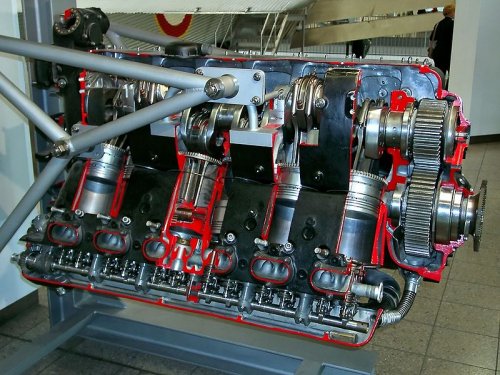 Daimler-Benz-DB 601A.jpg128.1 KB · Views: 510
 -
 Ki-61-Ⅱ.jpg41.1 KB · Views: 564
 -
 Ki-61-Ⅱ kai with bubble canopy.jpg243.1 KB · Views: 580
 -
 PROTOTYPE SKIN COOLER TYPE AND KI-61-Ⅱ.jpg163.3 KB · Views: 687
 -
 HA40 HA140 DB601A0001.jpg269.4 KB · Views: 798
- Joined
- 9 October 2009
- Messages
- 21,979
- Reaction score
- 13,647
blackkite said:Oh! Only Russian pilots knew how to use P-39. I think German's fuel quality was very low same as Japanese one at the day, this is one of the reason why P-39 could fight with BF109F. But also I think it's very difficult to use P-39's low initial speed, not straight trajectory 37mm canon against fighters. Russian P-39 drivers had good skill. Honestly speaking, I like P-39. Japan could not built such a complicated aircraft at the day.
Pepe Rezende said:Believe it or not, Soviet aces said the P-39 turned better than BF-109s. By the way, Rob was very complex and was a sucessfull design according to Japanese sources. It's Achilles heel was the cooling system. It was projected a new one with traditional radiators for the series aircraft.
Pepe
A quick detour: http://www.secretprojects.co.uk/forum/index.php/topic,10781.0.html
Now back to your regularly scheduled programming.
blackkite
Don't laugh, don't cry, don't even curse, but.....
- Joined
- 31 May 2007
- Messages
- 8,821
- Reaction score
- 7,721
Pepe Rezende said:Believe it or not, Soviet aces said the P-39 turned better than BF-109s.
I think P-39's moment of inertia was not so large nevertheless It's heavy weight, because It's engine and radiator were located middle of the plane same as recent F-1 car. Small moment of inertia might be contribute to quick turn in low altitude. Recently I read that P-39 turned quickly at low altitude.
blackkite
Don't laugh, don't cry, don't even curse, but.....
- Joined
- 31 May 2007
- Messages
- 8,821
- Reaction score
- 7,721
Hi!
http://www.cg-site.net/archives/cg_post_old/28172
http://www.cg-site.net/archives/cg_post_old/28172
Attachments
-
 japanese_army_xf-kawasaki_ki-64_002.jpg12.2 KB · Views: 159
 -
 japanese_army_xf-kawasaki_ki-64_003.jpg33.7 KB · Views: 132
 -
 japanese_army_xf-kawasaki_ki-64_004.jpg62.3 KB · Views: 171
 -
 org28172_3_177434.jpg209.4 KB · Views: 182
 -
 org28172_2_177433.jpg355.2 KB · Views: 167
 -
 org28172_1_177432.jpg354.1 KB · Views: 171
 -
 org28172_0_177431.jpg349.6 KB · Views: 183
 -
 Ki-64.jpg57.9 KB · Views: 193
blackkite
Don't laugh, don't cry, don't even curse, but.....
- Joined
- 31 May 2007
- Messages
- 8,821
- Reaction score
- 7,721
blackkite
Don't laugh, don't cry, don't even curse, but.....
- Joined
- 31 May 2007
- Messages
- 8,821
- Reaction score
- 7,721
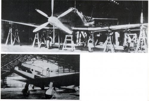
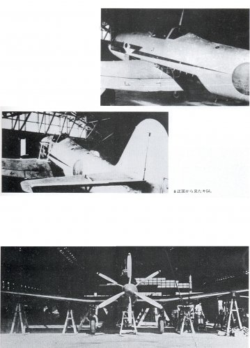
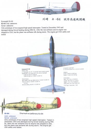
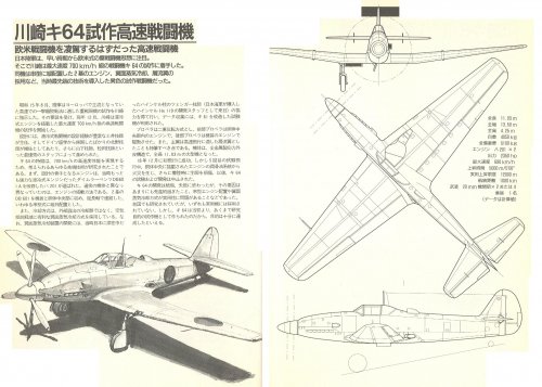
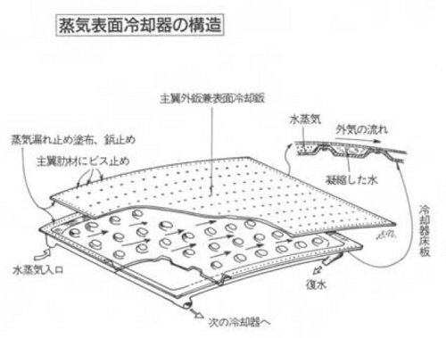
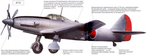
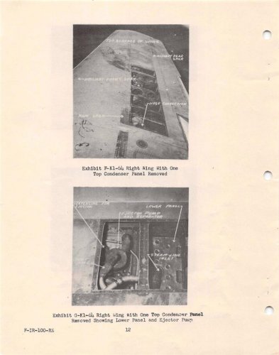
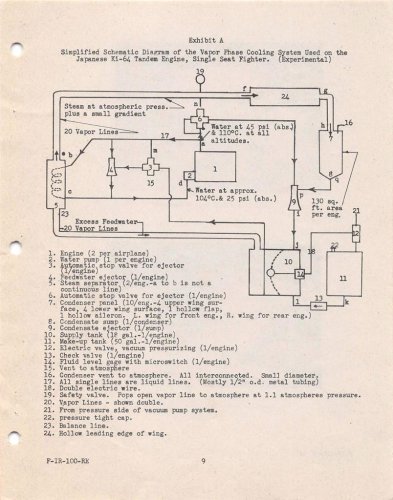
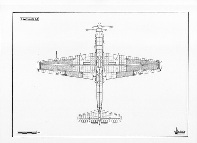
The engine of Ki-64 experimental fighter was cooled by steam surface cooler.
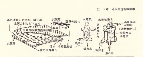
The outer surface of wing was used as steam surface cooler.
The thickness of the outer plate wings was 2 mm to withstand stress and thermal buckling. Spot welding of the 6-mm-deep sole plate was carried out to this outer plate to make the steam passage.
There were eight steam skin coolers in the under surface of the wing, eight coolers in the upper surface of the wing, two coolers in the under surface of the flap and two coolers in the upper surface of the flap. Steam skin coolers were constituted from total of 20 pieces.
With the ordinary engine, although the outlet pressure of a cooling water pump is 1.5 atmospheres(1.5ata), with Ha 201 engine of Ki-64, the outlet pressure of the cooling water pump is set to 4.8 atmospheres(4.8ata) quite highly.
The pressure of cooling water after cooling an engine is 4.2 atmospheres(4.2ata), and temperature is about 110degree centigrade.
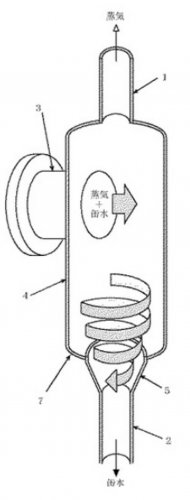
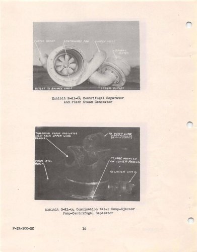
This cooling water's passage of whirlpool type centrifugal steam separator will generate a lot of steam from the center of steam separator.
At this time, cooling water is cooled to 103degree centigrade by steam evaporation latent heat.
The temperature of the steam which occurred at the center of steam separator is 103degree centigrade, pressure is 1.1 atmospheres(1.1ata), with a steam surface cooler, it is cooled and this steam serves as flocculated water.
Flocculated water is pressurized with a small pump and returned to the circulation system of cooling water.
The quantity of the steam which passes a steam surface cooler constitutes 2% of the quantity of the cooling water which circulates through the inside of an engine.
Even if a bullet hits a steam surface cooler, a hole is vacant, a flight is continuable for about 20 minutes.
蒸気 : steam, 水 : water
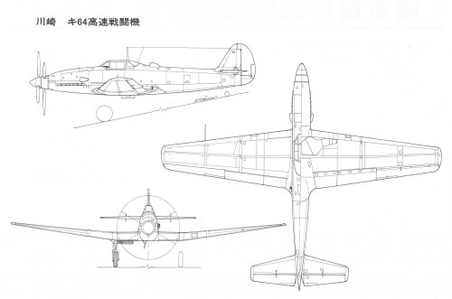
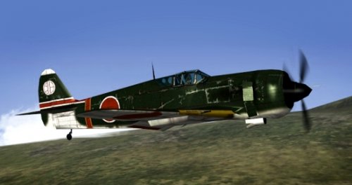
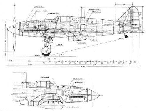
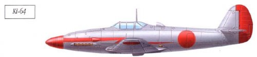
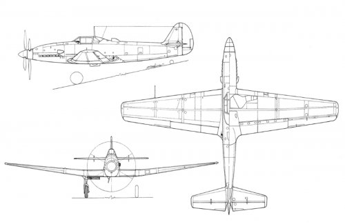
http://www.militaryfactory.com/aircraft/detail.asp?aircraft_id=955
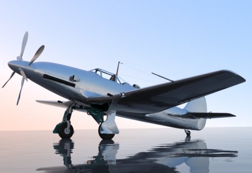
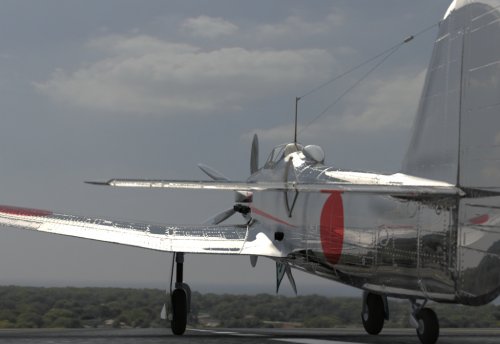
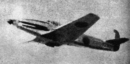
Following 3 side view is very good especially after engine exhaust nozzle.
The outer surface of wing was used as steam surface cooler.
The thickness of the outer plate wings was 2 mm to withstand stress and thermal buckling. Spot welding of the 6-mm-deep sole plate was carried out to this outer plate to make the steam passage.
There were eight steam skin coolers in the under surface of the wing, eight coolers in the upper surface of the wing, two coolers in the under surface of the flap and two coolers in the upper surface of the flap. Steam skin coolers were constituted from total of 20 pieces.
With the ordinary engine, although the outlet pressure of a cooling water pump is 1.5 atmospheres(1.5ata), with Ha 201 engine of Ki-64, the outlet pressure of the cooling water pump is set to 4.8 atmospheres(4.8ata) quite highly.
The pressure of cooling water after cooling an engine is 4.2 atmospheres(4.2ata), and temperature is about 110degree centigrade.
This cooling water's passage of whirlpool type centrifugal steam separator will generate a lot of steam from the center of steam separator.
At this time, cooling water is cooled to 103degree centigrade by steam evaporation latent heat.
The temperature of the steam which occurred at the center of steam separator is 103degree centigrade, pressure is 1.1 atmospheres(1.1ata), with a steam surface cooler, it is cooled and this steam serves as flocculated water.
Flocculated water is pressurized with a small pump and returned to the circulation system of cooling water.
The quantity of the steam which passes a steam surface cooler constitutes 2% of the quantity of the cooling water which circulates through the inside of an engine.
Even if a bullet hits a steam surface cooler, a hole is vacant, a flight is continuable for about 20 minutes.
蒸気 : steam, 水 : water
http://www.militaryfactory.com/aircraft/detail.asp?aircraft_id=955
Following 3 side view is very good especially after engine exhaust nozzle.
Attachments
blackkite
Don't laugh, don't cry, don't even curse, but.....
- Joined
- 31 May 2007
- Messages
- 8,821
- Reaction score
- 7,721
Hi!
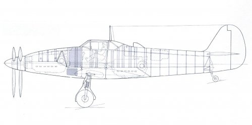
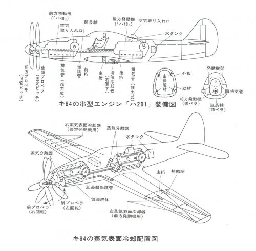
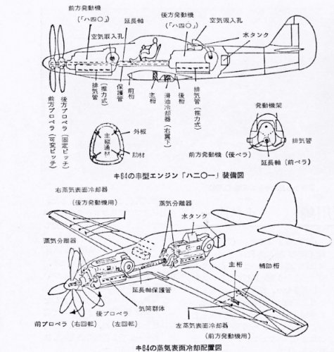
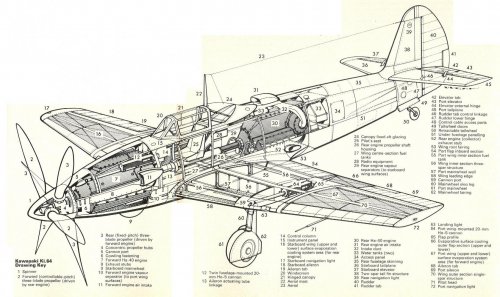
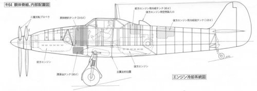
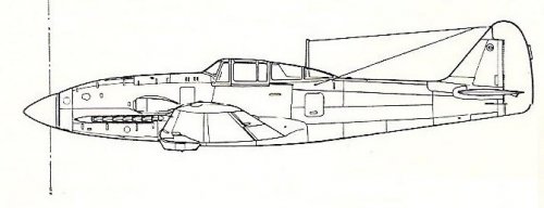
Drawing 1
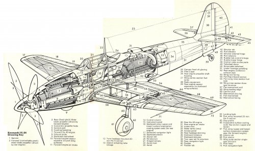
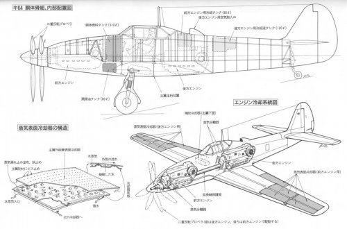
キ64胴体骨組、内部配置図 : Ki-64 Fuselage frame structure and inner general arrangement
胴体燃料タンク : Fuselage fuel tank
潤滑油タンク : Oil tank
前方エンジン用冷却液タンク : Forward engine cooling liquid tank
後方エンジン用冷却液タンク : Aft engine cooling liquid tank
主翼主桁位置 : Main wing main girder position
後方エンジン用空気取入口 : Aft engine air intake
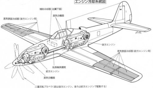
Drawing 2
エンジン冷却系統図 : Engine cooling system diagram
蒸気分離器 : Steam separator
蒸気表面冷却器(後方エンジン用): Steam skin cooler(for aft engine)
延長軸保護筒 : Extension shaft guard cylinder
補助冷却器(右翼下面) : Auxiliary cooler(right wing under side)
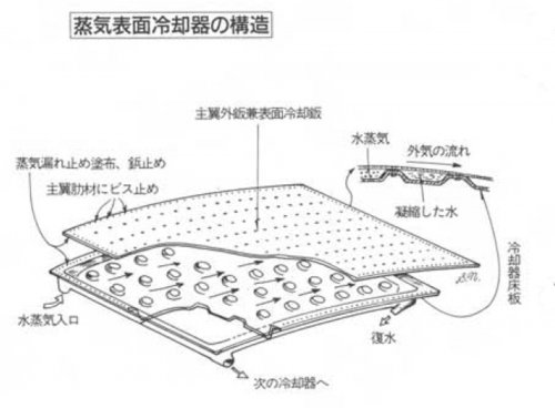
Drawing 3
蒸気表面冷却器の構造 : Steam skin cooler structure
主翼外板兼表面冷却器 : Main wing outer plate/skin cooler
冷却器床板 : Cooler floor plate
水蒸気 : Steam
復水 : Condensate
凝縮した水 : Condenced water
外気の流れ : Outer air stream
水蒸気入口 : Steam inlet
次の冷却器へ : To next cooler
蒸気漏れ止め塗布、鋲止め : Steamy leakage stop application and thumbtack stop
主翼肋材にビス止め : It's screwed on a main plane futtock.
Drawing 1
キ64胴体骨組、内部配置図 : Ki-64 Fuselage frame structure and inner general arrangement
胴体燃料タンク : Fuselage fuel tank
潤滑油タンク : Oil tank
前方エンジン用冷却液タンク : Forward engine cooling liquid tank
後方エンジン用冷却液タンク : Aft engine cooling liquid tank
主翼主桁位置 : Main wing main girder position
後方エンジン用空気取入口 : Aft engine air intake
Drawing 2
エンジン冷却系統図 : Engine cooling system diagram
蒸気分離器 : Steam separator
蒸気表面冷却器(後方エンジン用): Steam skin cooler(for aft engine)
延長軸保護筒 : Extension shaft guard cylinder
補助冷却器(右翼下面) : Auxiliary cooler(right wing under side)
Drawing 3
蒸気表面冷却器の構造 : Steam skin cooler structure
主翼外板兼表面冷却器 : Main wing outer plate/skin cooler
冷却器床板 : Cooler floor plate
水蒸気 : Steam
復水 : Condensate
凝縮した水 : Condenced water
外気の流れ : Outer air stream
水蒸気入口 : Steam inlet
次の冷却器へ : To next cooler
蒸気漏れ止め塗布、鋲止め : Steamy leakage stop application and thumbtack stop
主翼肋材にビス止め : It's screwed on a main plane futtock.
Attachments
windswords
ACCESS: Secret
- Joined
- 19 May 2009
- Messages
- 389
- Reaction score
- 218
Blackite-san,
Thank you for the translations.
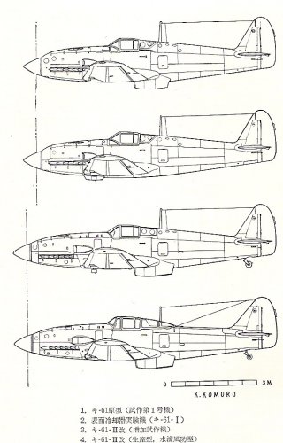
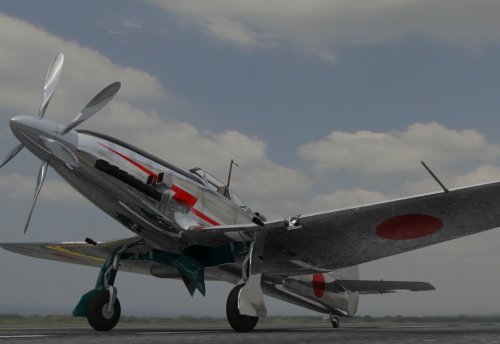
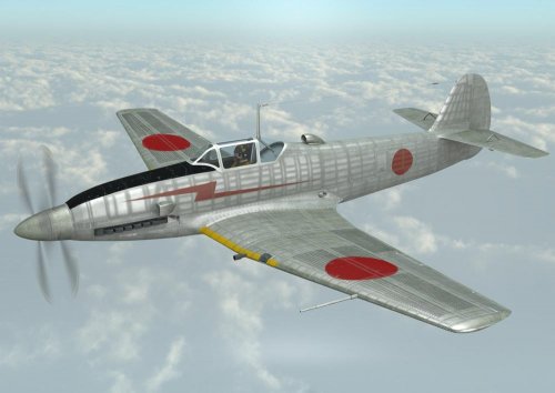
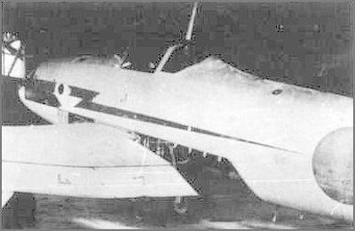
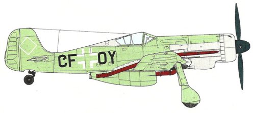
This is a little off topic but your earlier picture of the Ki-61 with prototype wing cooling got me thinking about what the ultimate Ki-61 would look like. So I took parts of the Ki-61 with wing cooling and the Ki-61-II-KAI later version with the "bubble" canopy and made the "Ki-61-III-KAI":
Besides the wing cooling of the experimental prototype I also used the retractable tail wheel of the earlier Hiens. Now, add a turbo supercharger like the Ki-100-II and a 4 bladed propeller (Ki-61-IV?) and you can go hunting for P-51 Mustangs and F8F Bearcats!
Thank you for the translations.
This is a little off topic but your earlier picture of the Ki-61 with prototype wing cooling got me thinking about what the ultimate Ki-61 would look like. So I took parts of the Ki-61 with wing cooling and the Ki-61-II-KAI later version with the "bubble" canopy and made the "Ki-61-III-KAI":
Besides the wing cooling of the experimental prototype I also used the retractable tail wheel of the earlier Hiens. Now, add a turbo supercharger like the Ki-100-II and a 4 bladed propeller (Ki-61-IV?) and you can go hunting for P-51 Mustangs and F8F Bearcats!
Attachments
blackkite
Don't laugh, don't cry, don't even curse, but.....
- Joined
- 31 May 2007
- Messages
- 8,821
- Reaction score
- 7,721
Oh beauty!!
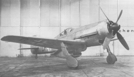
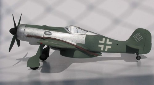
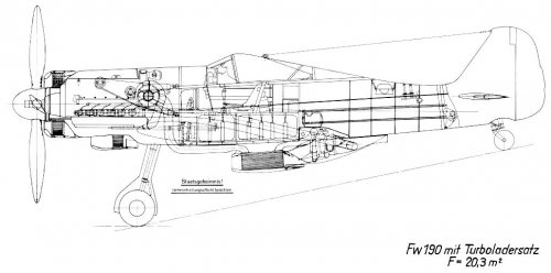
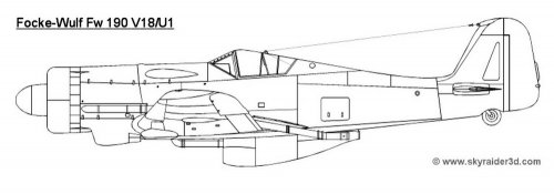
But when Hien had a turbocharger, we imagine very complicated shape like FW190V18/U1. Of course we do not need nose radiator using skin cooler.
Hien, even if it's improved, by no means however suitable it be for P-51 and F8F. ;D
http://modelingmadness.com/scott/axis/luft/fw/190/190v18.htm
But when Hien had a turbocharger, we imagine very complicated shape like FW190V18/U1. Of course we do not need nose radiator using skin cooler.
Hien, even if it's improved, by no means however suitable it be for P-51 and F8F. ;D
http://modelingmadness.com/scott/axis/luft/fw/190/190v18.htm
Attachments

- Joined
- 8 March 2009
- Messages
- 1,057
- Reaction score
- 1,299
Interesting looking report on ebay
http://www.ebay.com/itm/1946-AAF-T-2-JAPANESE-KI-64-FIGHTER-W-2-TANDEM-ENGINES-VAPOR-PHASE-COOLING-CD-/251815405296
http://www.ebay.com/itm/1946-AAF-T-2-JAPANESE-KI-64-FIGHTER-W-2-TANDEM-ENGINES-VAPOR-PHASE-COOLING-CD-/251815405296
Attachments
blackkite
Don't laugh, don't cry, don't even curse, but.....
- Joined
- 31 May 2007
- Messages
- 8,821
- Reaction score
- 7,721
Thanks a lot. Amazing document. 
Yes No.5 device is a steam separator.
Be careful that dotted line in the steam separator isn't a heat transfer tube.
http://www.secretprojects.co.uk/forum/index.php?action=dlattach;topic=10285.0;attach=562061;image
Yes No.5 device is a steam separator.
Be careful that dotted line in the steam separator isn't a heat transfer tube.
http://www.secretprojects.co.uk/forum/index.php?action=dlattach;topic=10285.0;attach=562061;image
Attachments
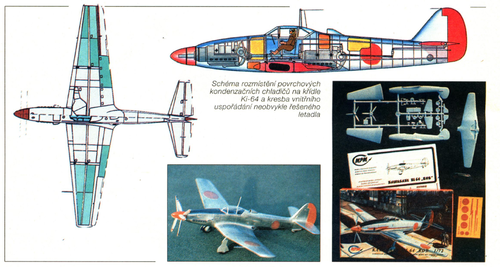
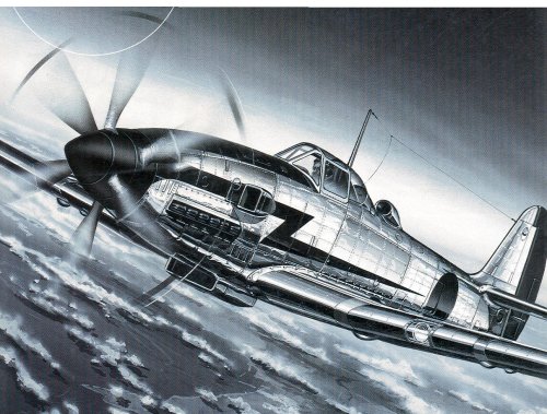
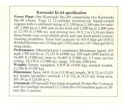
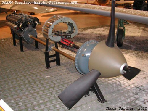
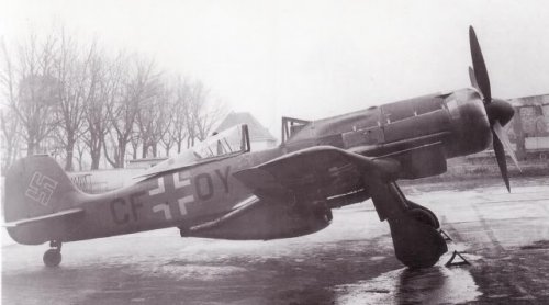
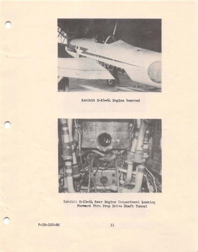
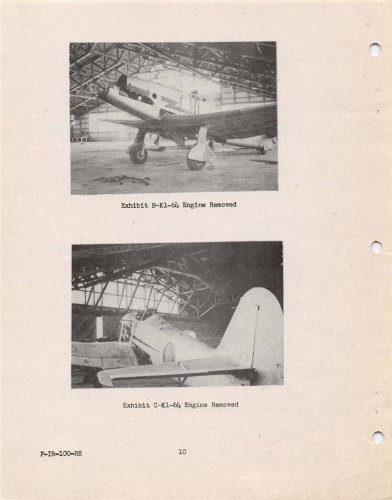
In October 1940, after analysing the new combat tactics used in Europe, the Kawasaki firm started a high-speed aircraft research programme, towards closing the technological gap with the Western World. They used two 1,175 hp Ha-40 (DB 601) engines connected in tandem by a 2 m length DB 615 power shaft and an evaporation cooling system based on the He 100 V8. All necessary information was acquired in Germany by engineer Jun Kitano in 1940.
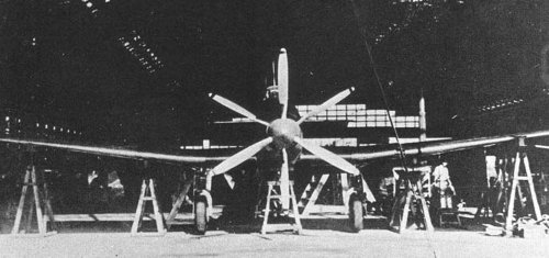
On 23 January 1941, Kawasaki was authorised by the Koku Hombu to start the construction of one experimental prototype that combined both technologies. Engineer Takeo Doi designed the laminar flow wings that would house the cooling system, with 200 litres of pressurised water at 1.1 atmospheres and 103 ºC. An 86 per cent of the wing area would be evaporation surfaces, including flaps. The propulsion system, named Ha-201, drived two contra-rotating airscrews, the front propeller being of fixed-pitch type and the rear propeller being of variable-pitch with Hamilton-Standard hydraulic system.
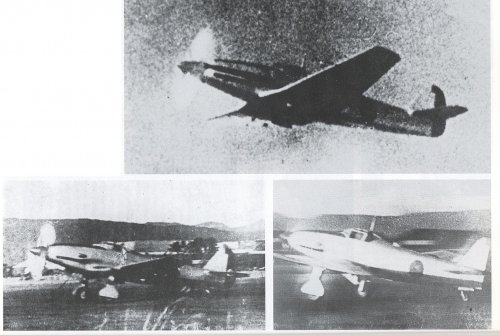
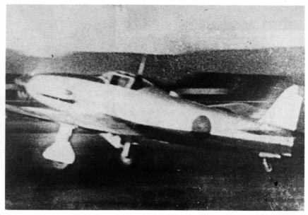
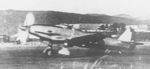
In October 1942 one Ki.61-I fighter was modified to test the effectiveness of the cooling system. The prototype performed 35 flying tests surpassing the top speed of the Ki.61 standard by 40 kph. The prototype was completed in November 1943, receiving the kitai number Ki.64. The flying tests started by the beginning of the month, experimenting vibration problems in the power shaft, malfunctioning of the contra-rotating airscrews and overheating of the rear engine. The engine burnt during the fifth flight and the pilot was forced to make an emergency landing, damaging the prototype that never flew again.
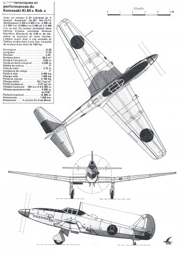
The production version, named Ki.64-Kai, would have been powered by two 1,350 hp Ha-140 turbocharged engines, with Methanol-water injection, driving a VDM/Sumitomo electrically controlled, constant-speed, contra-rotating propellers.
The cooling system was redesigned to operate a 4.8 atmospheres internal pressure and 110ºC, hoping to achieve a max speed of 800 kph. The proposed armament was two nose-mounted and two wing-mounted Ho-5 cannons.
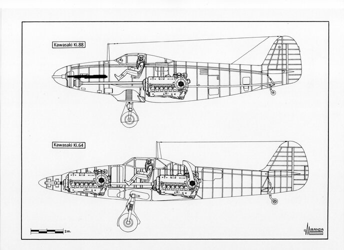
In the run of an unsatisfactory cooling of the rear engine, on February 1943 engineer Takeo Tsuchii started working on the design of the Ki.88, a Ki.61 modified with a Ha-140 engine, mounted behind the cockpit, driving a three-bladed propeller via an extension shaft. The Ki.88 would be fitted with a conventional radiator mounted on the bottom of the fuselage, with the objective to perfectionate an alternative cooling system for the rear engine of the Ki.64.
The prototype was expected to be completed by October 1943, but the smooth functioning of the evaporation cooling system installed on the Ki-61-I in 1942, made the IJA doubt the usefulness of the project. The Kawasaki firm decided to modify the Ki.88 by updating it as a fighter armed with a 37 mm Ho-203 cannon, firing through the propeller hub, and two 20 mm Ho-5 (synchronized) cannons mounted in the nose.
In October 1943, the Ki.88 was dropped by the Koku Hombu due to poor combat results from the P-39 Airacobra, based on the same formula.
On 23 January 1941, Kawasaki was authorised by the Koku Hombu to start the construction of one experimental prototype that combined both technologies. Engineer Takeo Doi designed the laminar flow wings that would house the cooling system, with 200 litres of pressurised water at 1.1 atmospheres and 103 ºC. An 86 per cent of the wing area would be evaporation surfaces, including flaps. The propulsion system, named Ha-201, drived two contra-rotating airscrews, the front propeller being of fixed-pitch type and the rear propeller being of variable-pitch with Hamilton-Standard hydraulic system.
In October 1942 one Ki.61-I fighter was modified to test the effectiveness of the cooling system. The prototype performed 35 flying tests surpassing the top speed of the Ki.61 standard by 40 kph. The prototype was completed in November 1943, receiving the kitai number Ki.64. The flying tests started by the beginning of the month, experimenting vibration problems in the power shaft, malfunctioning of the contra-rotating airscrews and overheating of the rear engine. The engine burnt during the fifth flight and the pilot was forced to make an emergency landing, damaging the prototype that never flew again.
The production version, named Ki.64-Kai, would have been powered by two 1,350 hp Ha-140 turbocharged engines, with Methanol-water injection, driving a VDM/Sumitomo electrically controlled, constant-speed, contra-rotating propellers.
The cooling system was redesigned to operate a 4.8 atmospheres internal pressure and 110ºC, hoping to achieve a max speed of 800 kph. The proposed armament was two nose-mounted and two wing-mounted Ho-5 cannons.
In the run of an unsatisfactory cooling of the rear engine, on February 1943 engineer Takeo Tsuchii started working on the design of the Ki.88, a Ki.61 modified with a Ha-140 engine, mounted behind the cockpit, driving a three-bladed propeller via an extension shaft. The Ki.88 would be fitted with a conventional radiator mounted on the bottom of the fuselage, with the objective to perfectionate an alternative cooling system for the rear engine of the Ki.64.
The prototype was expected to be completed by October 1943, but the smooth functioning of the evaporation cooling system installed on the Ki-61-I in 1942, made the IJA doubt the usefulness of the project. The Kawasaki firm decided to modify the Ki.88 by updating it as a fighter armed with a 37 mm Ho-203 cannon, firing through the propeller hub, and two 20 mm Ho-5 (synchronized) cannons mounted in the nose.
In October 1943, the Ki.88 was dropped by the Koku Hombu due to poor combat results from the P-39 Airacobra, based on the same formula.
Attachments
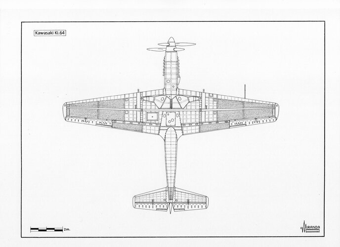
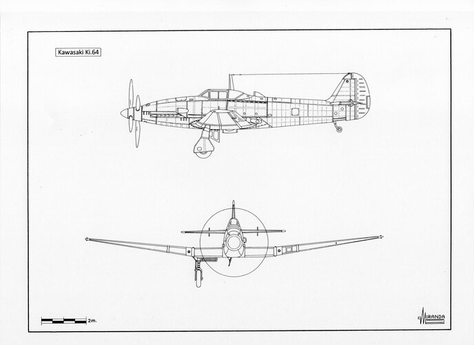
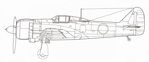
The large external hinge on the elevator, isnt the hinge, but counterweights, you can find them on almost all Kawasaki planes of that time.Here's a another 3 view. Notice the air scoop on the starboard (right) wing just inboard of the landing gear. There appears to a large external hinge on the elevator. Why is it so big?
Similar threads
-
 other less known japanese aircraft projects
- Started by airman
- Replies: 14
-
 Kawasaki Ki-119 Experimental Fighter-Bomber
- Started by blackkite
- Replies: 12
-
-

-
Kawasaki Ki-38 Experimental Two-Seat Twin-Engined Fighter/Ground Attack
- Started by blackkite
- Replies: 5