- Joined
- 11 March 2006
- Messages
- 8,626
- Reaction score
- 3,810

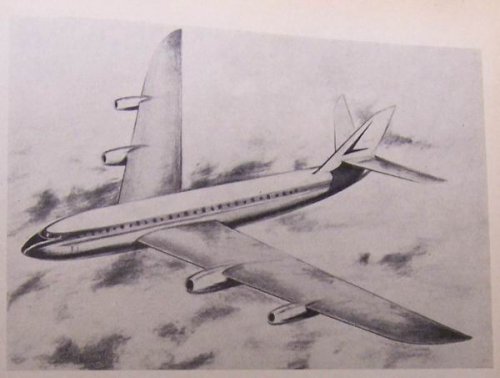
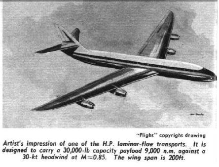
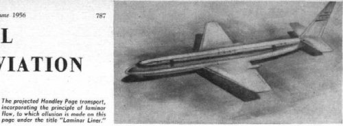
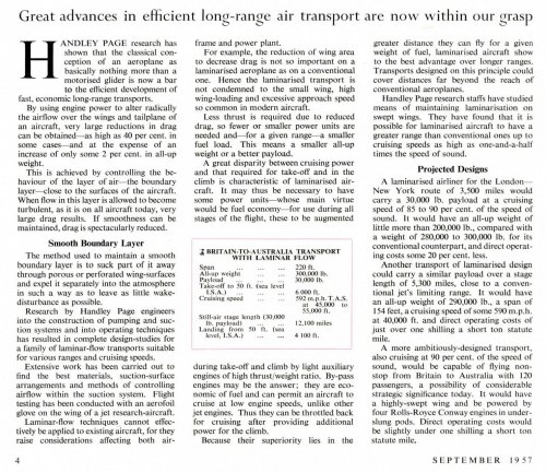
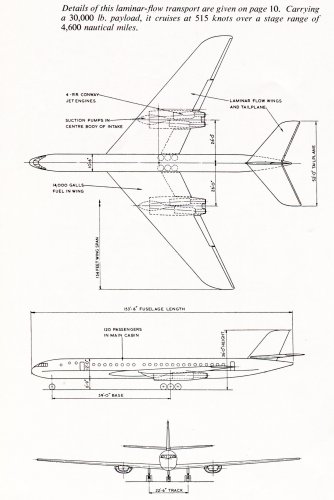
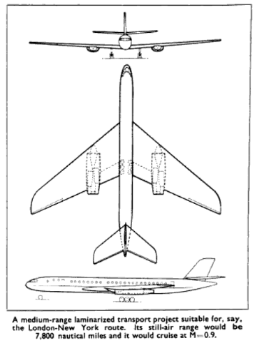
Interesting that the design placed the engines in external pods - I thought that during this period, the British aero industry was still committed to wing-root installations. The plumbing necessary for the suction system would seem like another reason to bury the engines internally and the arrangements of the pods on this design doesn't seem to use them to resist wing twist.Three views of two Laminar Flow projects from the Autumn 1957 Handley Page Bulletin... Project A was designed to cruise at Mach 0.85, Project B (similar to the HP108) at Mach 0.9...
Zeb
Interesting that the design placed the engines in external pods - I thought that during this period, the British aero industry was still committed to wing-root installations. The plumbing necessary for the suction system would seem like another reason to bury the engines internally and the arrangements of the pods on this design doesn't seem to use them to resist wing twist.
But the ducts and pipework would mostly lead to the engines.The wings would be full of ducts and pipework.
Chris