4.1.2 General Dynamics
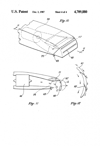
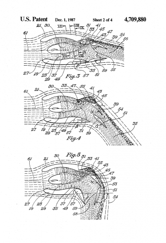
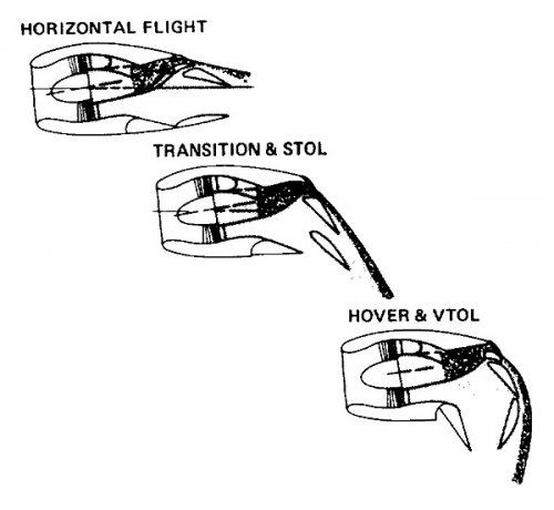
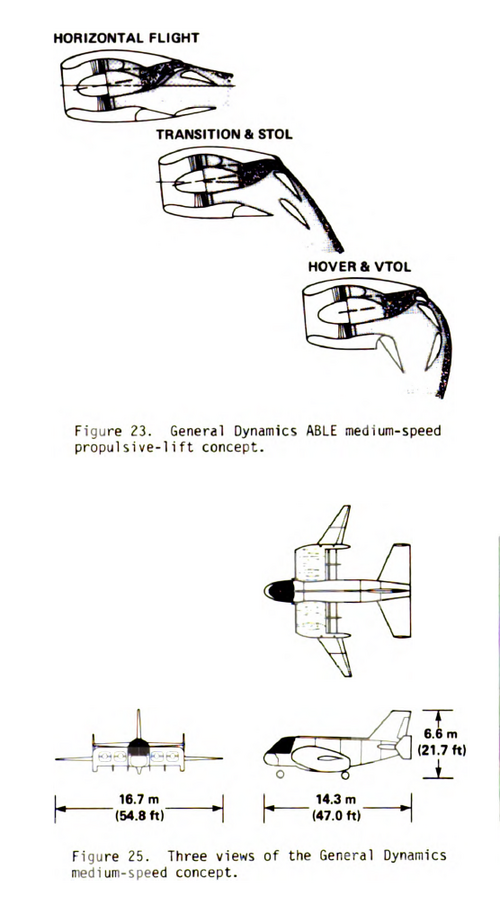
A medium-speed concept studied by General Dynamics, Fort Worth Division, features a powered lift system referred to as ABLE (Advanced Blown Lift Enhancement). The heart of this system is a "lifting nacelle" integrated into the wing that vectors the thrust of turbofan engines by using a series of movable flaps to make up the nozzle as illustrated in Fig. 23. One flap forms the upper surface of the two-dimensional nozzle, and two flaps form the lower surface. The upper flap has two slots. The upper forward slot forms the high-aspect ratio nozzle for the turbine engine exhaust, and the upper aft slot is a boundary layer control slot. The intent is to energize the external boundary layer and thus maintain attached airflow over the "lifting nacelles" to produce significant gains in STOL and transition performance and in aircraft controllability in these modes of flight. In forward flight, the flaps are arranged as shown on the left in Fig. 23, and in transition flight the flaps are deflected into intermediate positions as in the center of the figure. In hover flight (right in Fig. 23) the lower aft flap becomes a part of the aft wall of a vertical-thrust nozzle. The lower forward flap becomes the forward wall of the nozzle and provides a generous radius of the inside of the turn to reduce separation.
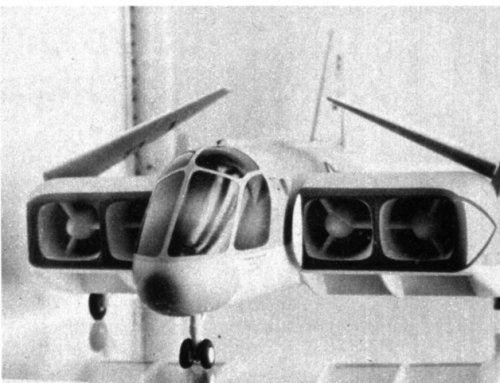
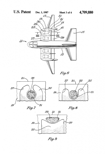
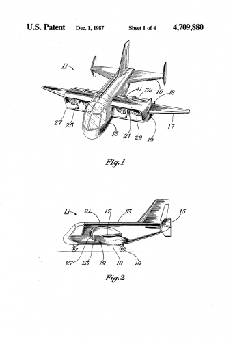
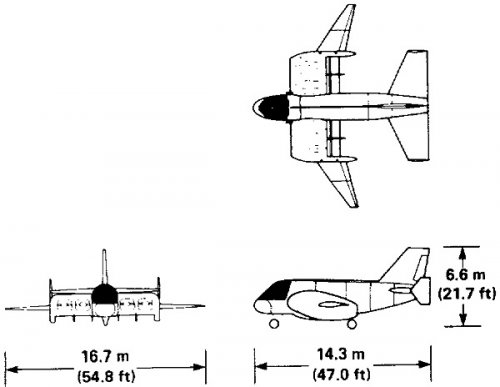
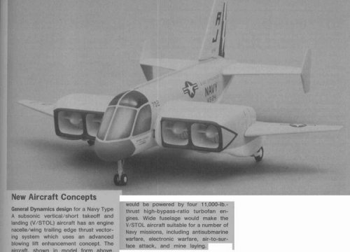
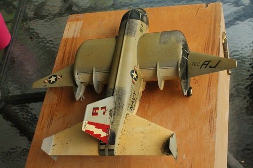
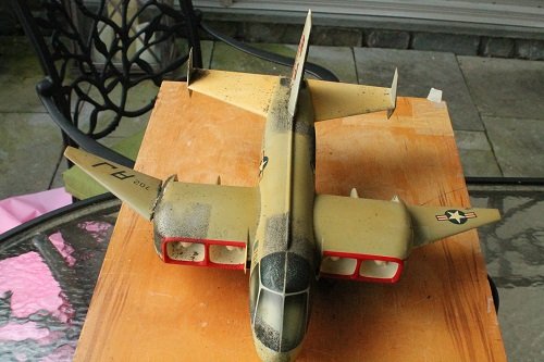
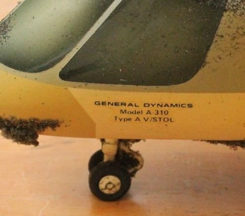
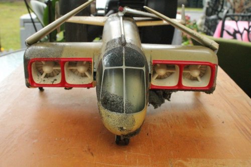
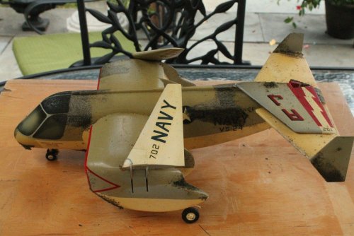
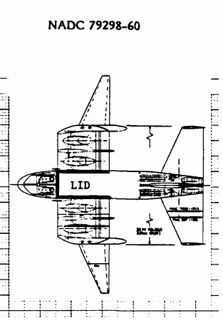
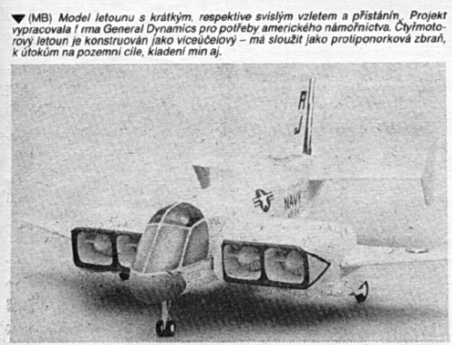
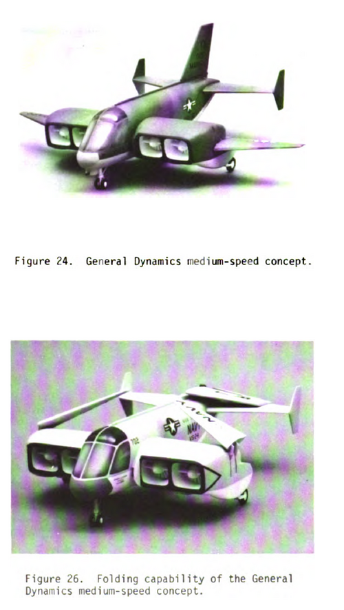
This propulsive lift system has been used in a configuration (A-311) illustrated by the model in Fig. 24. A three-view sketch is shown in Fig. 25, and the means of providing folding capability for a Navy configuration is illustrated in Fig. 26. Reference 3 gives a more complete description of this concept.
Four turbofan engines are used in the lifting nacelles of configuration A-311. The fans are cross-shaftedtogether using bevel gears in the fan nose bullets for engine-out considerations. Two load compressors are mounted between the inboard engines and the fuselage and are driven directly from the cross shaft. These compressors provide co_ressed air to the pitch trim/control system in the aft fuselage. This compressed air drives two air turbines which in turn drive two fans. The fan exhaust passes through dual nozzles which can be aimed up or down using a movable deflection system. Roll control in hover is achieved by biasing the thrust of the main engines either left or right through the cross shaft. Yaw control in hover is achieved by differentially deflecting the main engine nozzle flaps fore and aft on opposite sides of the aircraft.