
You are using an out of date browser. It may not display this or other websites correctly.
You should upgrade or use an alternative browser.
You should upgrade or use an alternative browser.
Flying Saucer as a real spacecraft design - pros&cons
- Thread starter publiusr
- Start date
martinbayer
ACCESS: Top Secret
- Joined
- 6 January 2009
- Messages
- 2,408
- Reaction score
- 2,129
Any "flying saucer" geometry is still one of the silliest spacecraft designs ever in terms of exposed external surface vs. internal volume - what is the underlying cause of your apparently unique fixation with that yesteryear UFO craze shape? Form Follows Function, not the other way round.Well, that may be more purely decorative than even Bono's saucer...
Last edited:
Any "flying saucer" geometry is still one of the silliest spacecraft designs ever in terms of exposed external surface vs. internal volume - what is the underlying cause of your apparently unique fixation with that yesteryear UFO craze shape? Form Follows Function, not the other way round.
The weight also spread over a larger surface,so lower (wing) loading and faster slow down. And more spreaded heatAny "flying saucer" geometry is still one of the silliest spacecraft designs ever in terms of exposed external surface vs. internal volume - what is the underlying cause of your apparently unique fixation with that yesteryear UFO craze shape? Form Follows Function, not the other way round.
Eliminating the bulk of the internal volume. Basically... useless.A saucer is a just a capsule flattened way down.
Eliminating the bulk of the internal volume. Basically... useless.
Somewhat, though to be fair the Apollo Lenticular had pretty much the same internal space, and had the ability to land on an airstrip as well. (Without landing gear
") ) Unfortunate part is it had sucy water landing characteristics but then again so did most "gliding" designs.
) Unfortunate part is it had sucy water landing characteristics but then again so did most "gliding" designs.Randy
A shuttle-C type saucer craft was looked at---pages 6-7
That was a *payload.* And a silly one: whether that was a radar dish, an optical mirror or, more likely, an aerobraking shield, you're far better off shipping it in segments and deploying on orbit.A shuttle-C type saucer craft was looked at---pages 6-7
This one?Somewhat, though to be fair the Apollo Lenticular had pretty much the same internal space,

It also had a diameter of 192 inches to Apollos 154. 38 inches ain't nuthin'. And the
"internal volume" was in the form of a separate external pressurized module.
A newer look.
 falsesteps.wordpress.com
Now in terms of a wide surface area, perhaps the Lenz effect can play a part.
View: https://m.youtube.com/watch?time_continue=12&v=Sq0FsvkPMgo&embeds_referring_euri=https%3A%2F%2Fscitechdaily.com%2F&source_ve_path=Mjg2NjY&feature=emb_logo

You may not need this technology
 en.m.wikipedia.org

 futurism.com
But I could see a cryogenic filled saucer rocket using a field effect sled for a boost.
There is where a wide footprint can help you. We have big magnets thanks to fusion research.
The biggest reason I want something like a Bono saucer is that the payload can be wide and in one piece.
Yes you can assemble things in orbit—but since ISS…I see little being done.
I am under no illusion this would be “anti-gravity:” just a maglev sled that might be a tad simpler….spinning turbopumps perhaps combined with a generator?
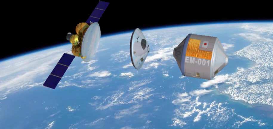
Fuji: Bringing the Mountain to the Masses
What it was: A Japanese proposal to develop a manned space capsule as part of an effort to produce an “open architecture” for space travel, announced to the public in September of 2001. Intended to…
falsesteps.wordpress.com
Now in terms of a wide surface area, perhaps the Lenz effect can play a part.
Defying Gravity: Scientists Solve Mystery of Magnetic Hovering Beyond Classical Physics
Scientists from the Technical University of Denmark (DTU) have confirmed the underlying physics of a newly discovered phenomenon of magnet levitation. In 2021, a scientist from Turkey published a research paper detailing an experiment where a magnet was attached to a motor, causing it to rotate rap
scitechdaily.com
You may not need this technology
Bitter electromagnet - Wikipedia
A tiny magnet just created the world's strongest magnetic field
"This creative technology could lead to small magnets that do big jobs in places like particle detectors, nuclear fusion reactors and diagnostic tools in medicine."
futurism.com
But I could see a cryogenic filled saucer rocket using a field effect sled for a boost.
There is where a wide footprint can help you. We have big magnets thanks to fusion research.
The biggest reason I want something like a Bono saucer is that the payload can be wide and in one piece.
Yes you can assemble things in orbit—but since ISS…I see little being done.
I am under no illusion this would be “anti-gravity:” just a maglev sled that might be a tad simpler….spinning turbopumps perhaps combined with a generator?
Last edited:
martinbayer
ACCESS: Top Secret
- Joined
- 6 January 2009
- Messages
- 2,408
- Reaction score
- 2,129
The theoretically optimum shape of any pressurized spacecraft is a sphere, which has the minimum surface area and associated structural mass to envelop a desired volume and is also the shape of an ideal pressure vessel. If you have an offset center of gravity, you also have a guaranteed foolproof orientation during reentry, which is why this shape was chosen for the Soviet Vostok/Voskhod crewed spacecraft. Saucer shapes lack that inherent aerodynamic reentry stability, as well as the minimum structural mass per volume property. I am truly baffled as to why you seem to assume that any future large single piece payloads would inevitably be in a circular pizza pie shape, rather than for example boxy or cylindrical. As best as I can tell, your line of wishful thinking is a foregone idée fixe solution in search of any even remotely relevant potential problems. That's not how actual real world engineering works though, where you start with cold hard requirements rather than with a favorite pet design.A saucer is a just a capsule flattened way down. Launch edge up to be slippery, then belly on for re-entry.
Last edited:
martinbayer
ACCESS: Top Secret
- Joined
- 6 January 2009
- Messages
- 2,408
- Reaction score
- 2,129
In return I'd encourage you to think outside the discworld paradigm as well - as I stated before in this forum, form follows function, not the other way round. For example, there are flexible/rollable solar cell panels that can nicely fit other form factors than a flat plane, such as say oh a cylinder, which jibes nicely with existing launch vehicles of various sizes and payload capabilities. I just get this sneaking suspicion that you are somehow preoccupied/obsessed with phonorecord/laserdisk shaped payloads for some reason or other...Having simple, wide pieces that can be assembled in space would lend itself to dishes for radar…energy generation, etc.
I like to think outside the tube
Last edited:
In return I'd encourage you to think outside the discworld paradigm as well - as I stated before in this forum, form follows function, not the other way round. For example, there are flexible/rollable solar cell panels that can nicely fit other form factors than a flat plane, such as say oh a cylinder, which jibes nicely with existing launch vehicles of various sizes and payload capabilities. I just get this sneaking suspicion that you are somehow preoccupied/obsessed with phonorecord/laserdisk shaped payloads for some reason or other...
Martin,
You are asking the wrong question.
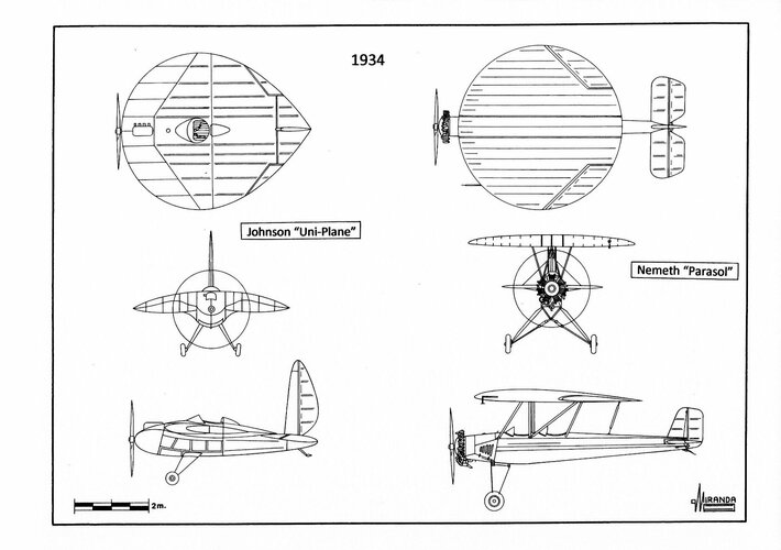
- In 1934 two airplanes fitted with circular wings were flown in the United States: the Johnson Uni-Plane (NX13680) and the Nemeth Parasol Monoplane (NX13851). Both prototypes were profusely described in Popular Aviation Magazine (June 1934, March 1935, and December 1936), Aero Digest (November 1934), Popular Science (March 1934) and Hearts Metrotone Newsreel (June 1934).
Possibly influenced by the American designs, a German aero modeler from Leipzig named Arthur Sack built the Fliegende Bierdeckel AS 1 air model, fitted with a 4 ft. 1 in diameter (NACA 280/2) circular wing, to take part in the National Contest of Aero Models with Combustion Engines held in Leipzig-Mockau in June 1939.
The air model, powered by one 0.65 hp Kratmo F 30B engine, could not even take off by itself, it had to be launched by hand proving to have rather poor flying qualities. However, the Generalluftzeugmeister Ernst Udet, fascinated by the circular wing and without any solid technical reason to base his decision, encouraged Sack to go on with his research and gave him the official support of Messerschmitt Abteilung L, the design team led by Dr. Alexander Lippisch that developed the Me 163 rocket fighter.
Lippisch was a designer specialized in tailless airplanes. Under their supervision Sack built three wind tunnel models (AS 2, AS 3 and AS 4) that were tested at the Aerodynamische Versuchsanstalt Göttingen (AVA) wind tunnel between 1940 and 1941.
The results of the tests were published by E. Hildebrand as ‘Dreikomponentenmessungen an einem Kreisflügel mi zwei klappen, Beritche Nr.40/14/40 vom 3.8.1940 und 41/14/5 vom 21.2.1941’ in 1941.
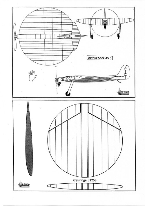
The new wing planform was accepted by the Deutsche Versuchsanstalt für Luftfahrt institute under the codename Messerschmitt-Kreisflügel J 1253.
In 1942 Sack built the AS 5 air model, with 4.1 ft. span and 10 lb. weight. The prototype was demonstrated to Luftwaffe officials early in 1943.
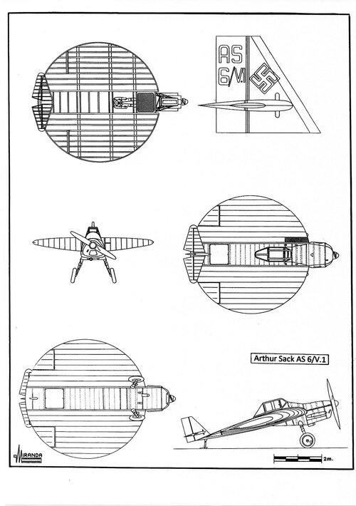
Abteilung L was dissolved in April, but the Luftwaffe Technisches Amt gave Sack permission to proceed with the AS 6, a full-sized manned aircraft. The construction of the prototype by Mitteldeutsche Metallwerke Flugplatz Werkstatt Company, started in December 1943 at Brandis-Waldpolenz airbase.
The airframe was built in wood/plywood, with the engine and the (non-retractable) main landing gear of one Messerschmitt Bf 108 Taifun, the cockpit and the pilot seat were seized from an ex-JFS 1 wrecked Messerschmitt Bf 109 B and the tail plane from an Klemm Kl 35 trainer.
Initial taxying trials were conducted on February 1944 by Rolf Baltabol, the Junkers ATG chief pilot, the airplane was painted in standard Luftwaffe RLM 70/71/65 camouflage pattern with the inscription ‘AS 6/V.1’ in the tailfin. ‘V.1’ came from Versuchmuster 1 (first prototype), it should not be mistaken with ‘V-1’ from Vergeltungswaffe 1 which was the propaganda name for the Fieseler Fi 103 flying bomb.
During the taxying it was verified that the control surfaces did not work, because they were positioned in the aerodynamic shadow generated by the wing. The circular wing planform is extremely inefficient because its low aspect ratio greatly increases the drag, especially at high angles of attack.
Five take off runs were attempted from the 1,200 m. landing strip of Brandis, without success. Sack’s design simply could not have provided adequate control authority once airborne. The right leg was broken during the last try and the Reichsluftfahrtministerium (RLM) lost interest in the project.
Between 1932 and 1935 the aerodynamicist Charles H. Zimmerman tested several types of low aspect ratio wings (with semicircular wingtips and Clark Y airfoils) in the NACA-Langley wind-tunnel, searching a solution to the Air Flivver problem of stall/spin accidents.
The development of a controlled vortex flow allows the low aspect ratio wing to avoid stalling at exceedingly high angle-of-attack and low speed. Zimmerman progressively reduced the center section in the wing of some scale models until it reached zero, with the wingtips forming a circular planform wing.
Their NACA report nº 539: Aerodynamic Characteristics of Several Airfoils of Low Aspect Ratio (1935) became the basis for the V-173 Zimmer Skimmer design of 1939, with U.S. Navy financing and Chance Vought Aircraft Division-Stratford workmanship.
The prototype Bu Aer no. 02978 was constructed with wood framework, plywood/fabric covering and powered by two 80 hp. Continental C-75 engines driving 16 foot 6 in three-bladed, variable pitch propellers, rotating in the opposite direction. These large propellers demanded a long fixed landing gear gave the V-173 a 22.15 degrees nose-high ground angle. Most of the airframe was the wing, which had an aspect ratio of 1:275, with semi-elliptical leading edge and trailing edge joined at a straight quarter-chord line.
The plane was test flown at Stratford on November 23, 1942 performing a take-off run of only 200 ft. at 29 mph, controlled flight at a 45 degrees angle-of-attack and landing in 20 ft. and 15 mph. The propellers were fitted in the wingtips, retaining the high-pressure air below the wing, actively cancelling the drag tip vortex, and providing uniform airflow over the entire wing, for exceptional ‘parachute lift’ effect.
Engine power was delivered to the propellers via a complex set of shafts with right angle gear drives, and a power cross shaft with over-running clutches, that ran behind the cockpit, connecting the engines gearboxes to ensure both propellers turned in a single engine scenario.
Each horizontal stabilizer acted as both aileron and elevator (ailevator).
Originally the pilot was lying in prone position, to promote streamlining, with glazed panels in the lower leading edge but this was changed to an upright seat because of his marginal comfort.
On January 19, 1942 Vought-Sikorsky submitted to the U.S. Navy the VS-315 proposal for a 425 mph STOL fighter. In February, the Navy requested a 1/3 scale wind-tunnel model, the VS-315 receiving the official designation XF5U-1 on September 10, 1942 and the wooden mock-up VS-313 was finished in June 1943.
The projected naval fighter had a lightweight aluminum structure with Metalite (balsa/aluminum sandwich) skin, 20 times as much power that the V-173 and increased top speed/landing speed ratio from a typical 4:1 to 10:1. Using two Pratt & Whitney R-2800-7 radial engines, rated at 1,350 hp. each, was expected a landing speed of 40 mph, a top speed of 425 mph. and a zero-roll take-off with a 25-knot headwind.
Powered by two 1,600 hp. P&W R-2000-2(D) turbo-supercharged engines with water injection, it was expected to reach 20 to 460 mph and 0 to 550 mph using two General Electric T31-GE-3 turboprops with 2,300 shp+600 lbf residual thrust and greater power-to-weight ratio. The proposed turbine-powered model was designated VS-341. With sufficient power, both rotors could generate more lift than weight for vertical take-off and landing operation, just keeping up with the warship forward speed. Powered by two turboprops, the airplane would hover motionless hanging under its rotors like a helicopter.
On July 15, 1944, the Navy signed a contract for two prototypes: one for static testing (Bu Aer nº 33959) and one (Bu Aer nº 33958) for flight evaluation. The XF5U-1 was completed on June 25, 1945 with retractable landing gear, catapult bridle hooks and arresting hook for carrier operation. Their R-2000-7 engines were buried into the wing, two circular air intakes with cooling fans were placed in the wing leading edge and four air exit flaps were opened on both upper and lower wing surfaces.
A pair of Hamilton Standard Hydromatic propellers from two F4U-4 Corsair fighters were installed, but the vibration tests performed on June 29, 1945 showed excessive mechanical vibration between the engine-propeller shafting, gear boxes, and airframe structure.
It was necessary to develop a new type of propellers, with articulated blades, like those used on helicopters. Each rotor consisted of two pair of wooden blades, one mounted ahead the other, that could flap fore and aft to alleviate the vibration at a high angle-of-attack, but the articulated rotors were not available until 1947.
The airplane was taxi tested on February 3, 1947 at Stratford, Connecticut, but, again, showed destructive cyclic forces and heavy loads that had not been acceptable with conventional rigid airscrews. Full flight tests were scheduled for December 1948 at Edwards AFB, but the development of the two-speed gearboxes delayed the program and the U.S. Navy suddenly cancelled the contract on March 17, 1947, with orders to destroy the prototype.
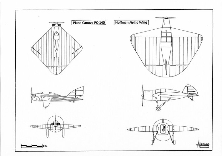
The Piana Canova PC-140, an Italian light plane fitted with rhomboidal wing, was flown in 1931. Three years later flew the Hoffman Flying Wing, an American light plane with rhomboidal/semi-circular composite wing planform. During its flight tests, both planes showed remarkable STOL characteristics at extreme angle-of-attack, proving the usefulness of the extreme low aspect ratio wings.
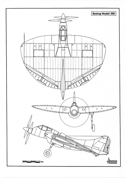
The concept was used by Boeing designers in their projects 390 and 391 high-performance STOL fighters, fitted with semi-elliptical/semi-circular wings, without the over-complication of the Vought rotors system.
The Model 390 was powered by one Pratt & Whitney R-4360-3 air-cooled radial engine, rated at 3,000 hp, driving counter-rotating three-blade propellers by means of a drive shaft. The Model 391was powered by one Pratt & Whitney R-4360-17 with two-stage mechanical supercharger, rated at 3,500 hp. Both engines were mounted in the center of the wing, behind the cockpit.
Boeing submitted its proposals to the US Navy in the spring of 1943, but the project was rejected in favor of the Zimmerman aircraft.
Boeing 390 technical data
Wingspan: 32.8 ft (10 m), length: 33.8 ft (10.3 m), height: 13.7 ft (4.2 m), wing area: 567 sq. ft (51 sq. m), max weight: 14,000 lbs. (6,432 kg), estimated max speed: 414 mph (666 kph), estimated climb rate: 4,250 ft/minute, proposed armament: four wing mounted 20 mm cannon.
Boeing 391 technical data
Wingspan: 32.8 ft (10 m), length: 33.8 ft (10.3 m), height: 13.7 ft (4.2 m), wing area: 567 sq. ft (51 sq. m), max weight: 14,500 lbs (6,569 kg), estimated max speed: 452 mph (727 kph), estimated climb rate: 4,250 ft/minute, proposed armament: four wing mounted 20 mm cannon.
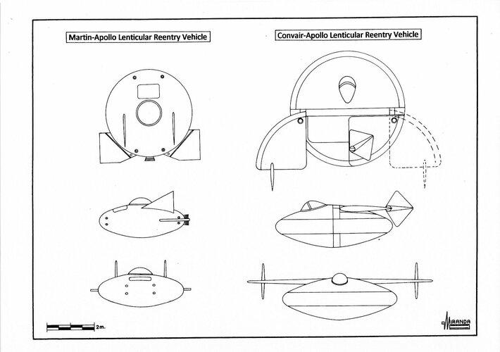
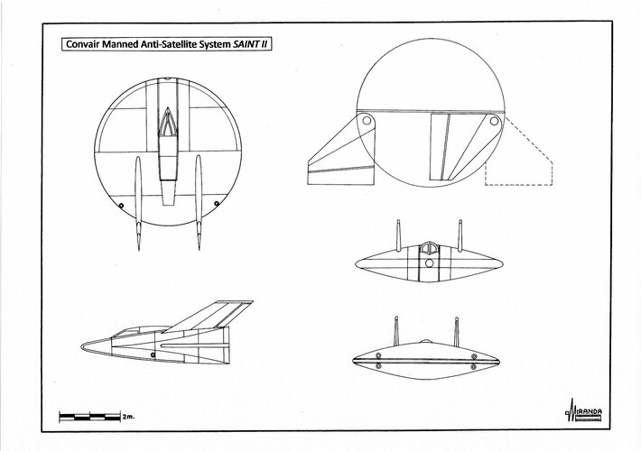
Though the Valkyrie was cancelled, Convair used the aerodynamic and ablative heat shield lessons learned from Pye Wacket to design several lenticular re-entry spaceships. The ultimate derivative of the Pye Wacket project was the Convair Saint II, a Manned Anti-Satellite System (MASS) proposed to the USAF on October 17, 1963.
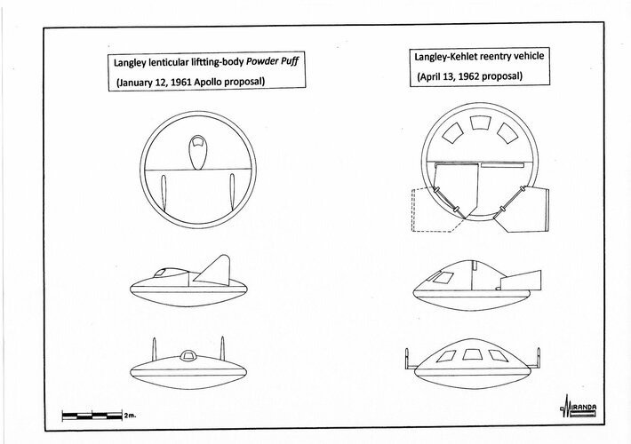
Lenticular shapes were one of three early contenders for manned spacecraft in the Apollo space program.
On January 12, 1961 four lenticular configurations with 3.95 m, 4.9 m, 3.7 m, and 3.3 m of diameter were proposed by NASA-Langley, Convair, Glenn L. Martin and General Electric.
On April 13, 1962, the NASA-Langley engineer Alan B. Kehlet proposed a lenticular vehicle, with foldable aerodynamic flaps, capable to performing orbital missions while possessing atmospheric maneuverability for glide landings.
Lenticular configuration had a lift-to-drag ratio of 2 compared with the 1.0 of the dart configurations, however lenticular concepts were not considered during the Shuttle design studies.
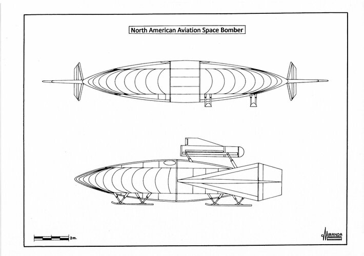
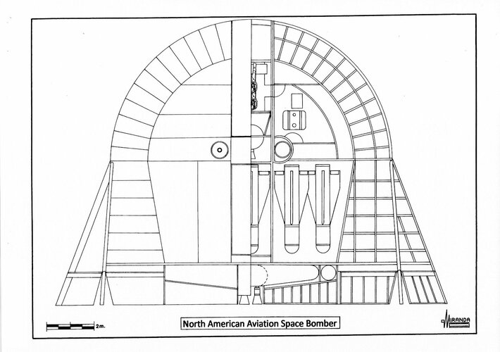
In 1962 North American Aviation proposed their Study 1963, a lenticular space bomber with 12 m diameter, a crew of four and armed with four thermonuclear weapons.
Possibly influenced by the American designs, a German aero modeler from Leipzig named Arthur Sack built the Fliegende Bierdeckel AS 1 air model, fitted with a 4 ft. 1 in diameter (NACA 280/2) circular wing, to take part in the National Contest of Aero Models with Combustion Engines held in Leipzig-Mockau in June 1939.
The air model, powered by one 0.65 hp Kratmo F 30B engine, could not even take off by itself, it had to be launched by hand proving to have rather poor flying qualities. However, the Generalluftzeugmeister Ernst Udet, fascinated by the circular wing and without any solid technical reason to base his decision, encouraged Sack to go on with his research and gave him the official support of Messerschmitt Abteilung L, the design team led by Dr. Alexander Lippisch that developed the Me 163 rocket fighter.
Lippisch was a designer specialized in tailless airplanes. Under their supervision Sack built three wind tunnel models (AS 2, AS 3 and AS 4) that were tested at the Aerodynamische Versuchsanstalt Göttingen (AVA) wind tunnel between 1940 and 1941.
The results of the tests were published by E. Hildebrand as ‘Dreikomponentenmessungen an einem Kreisflügel mi zwei klappen, Beritche Nr.40/14/40 vom 3.8.1940 und 41/14/5 vom 21.2.1941’ in 1941.
The new wing planform was accepted by the Deutsche Versuchsanstalt für Luftfahrt institute under the codename Messerschmitt-Kreisflügel J 1253.
In 1942 Sack built the AS 5 air model, with 4.1 ft. span and 10 lb. weight. The prototype was demonstrated to Luftwaffe officials early in 1943.
Abteilung L was dissolved in April, but the Luftwaffe Technisches Amt gave Sack permission to proceed with the AS 6, a full-sized manned aircraft. The construction of the prototype by Mitteldeutsche Metallwerke Flugplatz Werkstatt Company, started in December 1943 at Brandis-Waldpolenz airbase.
The airframe was built in wood/plywood, with the engine and the (non-retractable) main landing gear of one Messerschmitt Bf 108 Taifun, the cockpit and the pilot seat were seized from an ex-JFS 1 wrecked Messerschmitt Bf 109 B and the tail plane from an Klemm Kl 35 trainer.
Initial taxying trials were conducted on February 1944 by Rolf Baltabol, the Junkers ATG chief pilot, the airplane was painted in standard Luftwaffe RLM 70/71/65 camouflage pattern with the inscription ‘AS 6/V.1’ in the tailfin. ‘V.1’ came from Versuchmuster 1 (first prototype), it should not be mistaken with ‘V-1’ from Vergeltungswaffe 1 which was the propaganda name for the Fieseler Fi 103 flying bomb.
During the taxying it was verified that the control surfaces did not work, because they were positioned in the aerodynamic shadow generated by the wing. The circular wing planform is extremely inefficient because its low aspect ratio greatly increases the drag, especially at high angles of attack.
Five take off runs were attempted from the 1,200 m. landing strip of Brandis, without success. Sack’s design simply could not have provided adequate control authority once airborne. The right leg was broken during the last try and the Reichsluftfahrtministerium (RLM) lost interest in the project.
Between 1932 and 1935 the aerodynamicist Charles H. Zimmerman tested several types of low aspect ratio wings (with semicircular wingtips and Clark Y airfoils) in the NACA-Langley wind-tunnel, searching a solution to the Air Flivver problem of stall/spin accidents.
The development of a controlled vortex flow allows the low aspect ratio wing to avoid stalling at exceedingly high angle-of-attack and low speed. Zimmerman progressively reduced the center section in the wing of some scale models until it reached zero, with the wingtips forming a circular planform wing.
Their NACA report nº 539: Aerodynamic Characteristics of Several Airfoils of Low Aspect Ratio (1935) became the basis for the V-173 Zimmer Skimmer design of 1939, with U.S. Navy financing and Chance Vought Aircraft Division-Stratford workmanship.
The prototype Bu Aer no. 02978 was constructed with wood framework, plywood/fabric covering and powered by two 80 hp. Continental C-75 engines driving 16 foot 6 in three-bladed, variable pitch propellers, rotating in the opposite direction. These large propellers demanded a long fixed landing gear gave the V-173 a 22.15 degrees nose-high ground angle. Most of the airframe was the wing, which had an aspect ratio of 1:275, with semi-elliptical leading edge and trailing edge joined at a straight quarter-chord line.
The plane was test flown at Stratford on November 23, 1942 performing a take-off run of only 200 ft. at 29 mph, controlled flight at a 45 degrees angle-of-attack and landing in 20 ft. and 15 mph. The propellers were fitted in the wingtips, retaining the high-pressure air below the wing, actively cancelling the drag tip vortex, and providing uniform airflow over the entire wing, for exceptional ‘parachute lift’ effect.
Engine power was delivered to the propellers via a complex set of shafts with right angle gear drives, and a power cross shaft with over-running clutches, that ran behind the cockpit, connecting the engines gearboxes to ensure both propellers turned in a single engine scenario.
Each horizontal stabilizer acted as both aileron and elevator (ailevator).
Originally the pilot was lying in prone position, to promote streamlining, with glazed panels in the lower leading edge but this was changed to an upright seat because of his marginal comfort.
On January 19, 1942 Vought-Sikorsky submitted to the U.S. Navy the VS-315 proposal for a 425 mph STOL fighter. In February, the Navy requested a 1/3 scale wind-tunnel model, the VS-315 receiving the official designation XF5U-1 on September 10, 1942 and the wooden mock-up VS-313 was finished in June 1943.
The projected naval fighter had a lightweight aluminum structure with Metalite (balsa/aluminum sandwich) skin, 20 times as much power that the V-173 and increased top speed/landing speed ratio from a typical 4:1 to 10:1. Using two Pratt & Whitney R-2800-7 radial engines, rated at 1,350 hp. each, was expected a landing speed of 40 mph, a top speed of 425 mph. and a zero-roll take-off with a 25-knot headwind.
Powered by two 1,600 hp. P&W R-2000-2(D) turbo-supercharged engines with water injection, it was expected to reach 20 to 460 mph and 0 to 550 mph using two General Electric T31-GE-3 turboprops with 2,300 shp+600 lbf residual thrust and greater power-to-weight ratio. The proposed turbine-powered model was designated VS-341. With sufficient power, both rotors could generate more lift than weight for vertical take-off and landing operation, just keeping up with the warship forward speed. Powered by two turboprops, the airplane would hover motionless hanging under its rotors like a helicopter.
On July 15, 1944, the Navy signed a contract for two prototypes: one for static testing (Bu Aer nº 33959) and one (Bu Aer nº 33958) for flight evaluation. The XF5U-1 was completed on June 25, 1945 with retractable landing gear, catapult bridle hooks and arresting hook for carrier operation. Their R-2000-7 engines were buried into the wing, two circular air intakes with cooling fans were placed in the wing leading edge and four air exit flaps were opened on both upper and lower wing surfaces.
A pair of Hamilton Standard Hydromatic propellers from two F4U-4 Corsair fighters were installed, but the vibration tests performed on June 29, 1945 showed excessive mechanical vibration between the engine-propeller shafting, gear boxes, and airframe structure.
It was necessary to develop a new type of propellers, with articulated blades, like those used on helicopters. Each rotor consisted of two pair of wooden blades, one mounted ahead the other, that could flap fore and aft to alleviate the vibration at a high angle-of-attack, but the articulated rotors were not available until 1947.
The airplane was taxi tested on February 3, 1947 at Stratford, Connecticut, but, again, showed destructive cyclic forces and heavy loads that had not been acceptable with conventional rigid airscrews. Full flight tests were scheduled for December 1948 at Edwards AFB, but the development of the two-speed gearboxes delayed the program and the U.S. Navy suddenly cancelled the contract on March 17, 1947, with orders to destroy the prototype.
The Piana Canova PC-140, an Italian light plane fitted with rhomboidal wing, was flown in 1931. Three years later flew the Hoffman Flying Wing, an American light plane with rhomboidal/semi-circular composite wing planform. During its flight tests, both planes showed remarkable STOL characteristics at extreme angle-of-attack, proving the usefulness of the extreme low aspect ratio wings.
The concept was used by Boeing designers in their projects 390 and 391 high-performance STOL fighters, fitted with semi-elliptical/semi-circular wings, without the over-complication of the Vought rotors system.
The Model 390 was powered by one Pratt & Whitney R-4360-3 air-cooled radial engine, rated at 3,000 hp, driving counter-rotating three-blade propellers by means of a drive shaft. The Model 391was powered by one Pratt & Whitney R-4360-17 with two-stage mechanical supercharger, rated at 3,500 hp. Both engines were mounted in the center of the wing, behind the cockpit.
Boeing submitted its proposals to the US Navy in the spring of 1943, but the project was rejected in favor of the Zimmerman aircraft.
Boeing 390 technical data
Wingspan: 32.8 ft (10 m), length: 33.8 ft (10.3 m), height: 13.7 ft (4.2 m), wing area: 567 sq. ft (51 sq. m), max weight: 14,000 lbs. (6,432 kg), estimated max speed: 414 mph (666 kph), estimated climb rate: 4,250 ft/minute, proposed armament: four wing mounted 20 mm cannon.
Boeing 391 technical data
Wingspan: 32.8 ft (10 m), length: 33.8 ft (10.3 m), height: 13.7 ft (4.2 m), wing area: 567 sq. ft (51 sq. m), max weight: 14,500 lbs (6,569 kg), estimated max speed: 452 mph (727 kph), estimated climb rate: 4,250 ft/minute, proposed armament: four wing mounted 20 mm cannon.
Though the Valkyrie was cancelled, Convair used the aerodynamic and ablative heat shield lessons learned from Pye Wacket to design several lenticular re-entry spaceships. The ultimate derivative of the Pye Wacket project was the Convair Saint II, a Manned Anti-Satellite System (MASS) proposed to the USAF on October 17, 1963.
Lenticular shapes were one of three early contenders for manned spacecraft in the Apollo space program.
On January 12, 1961 four lenticular configurations with 3.95 m, 4.9 m, 3.7 m, and 3.3 m of diameter were proposed by NASA-Langley, Convair, Glenn L. Martin and General Electric.
On April 13, 1962, the NASA-Langley engineer Alan B. Kehlet proposed a lenticular vehicle, with foldable aerodynamic flaps, capable to performing orbital missions while possessing atmospheric maneuverability for glide landings.
Lenticular configuration had a lift-to-drag ratio of 2 compared with the 1.0 of the dart configurations, however lenticular concepts were not considered during the Shuttle design studies.
In 1962 North American Aviation proposed their Study 1963, a lenticular space bomber with 12 m diameter, a crew of four and armed with four thermonuclear weapons.
Attachments
Rhinocrates
ACCESS: Top Secret
- Joined
- 26 September 2006
- Messages
- 2,140
- Reaction score
- 4,543
Attachments
Rhinocrates
ACCESS: Top Secret
- Joined
- 26 September 2006
- Messages
- 2,140
- Reaction score
- 4,543
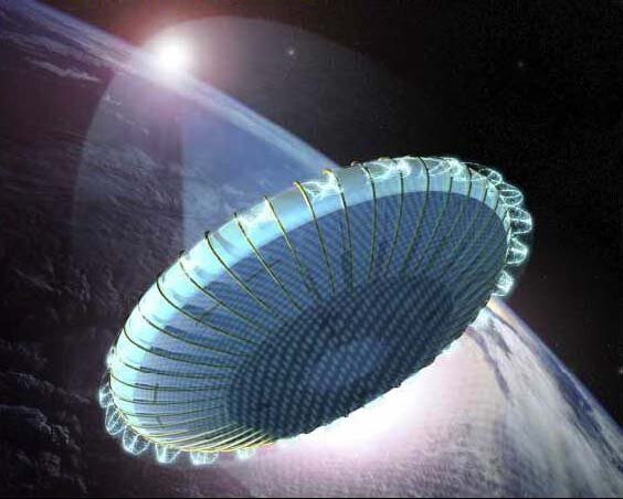
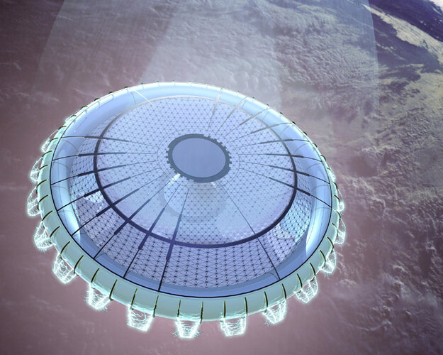
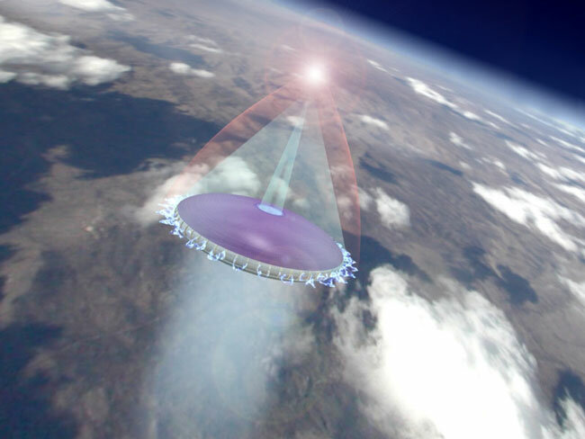
How big a spacecraft? If it doesn't have to land anywhere, imagine a torus spinning to generate 1/3-1 g at the perimeter, inflate an oblate spheroid in the middle and use it as a droplet radiator (heated coolant is ejected at the axis, centrifugal force drives the dropets down the membrane, loosing heat as they go, then it's collected in a gutter at the perimeter and pumped back up), stick a reactor on a long stick through the axis. The result looks like a fat umbrella. If one side's tough enough, it can be used for aerocapture manoeuvres. It would be a more compact version of this with the habs around the rim rather than on the stick:
Attachments

Last edited:
Rhinocrates
ACCESS: Top Secret
- Joined
- 26 September 2006
- Messages
- 2,140
- Reaction score
- 4,543
Then there are various lightsail concepts. Update on Starshot by Anton Petrov here.
View: https://www.youtube.com/watch?v=HwPTF_TZvWY
I imagine some of the methods used for BWBs can be used for rigid saucers.
Unlike spheres, which are best for holding higher volumes, a disk can present a lower profile when speed is needed…and being wide and filled with cryogenics, can allow more even support if we can get any maglev sleds built…perhaps any tuning needed for active cooling can double as coils….allowing something like this:
View: https://m.youtube.com/watch?v=AWojYBhvfjM&vl=en
Unlike spheres, which are best for holding higher volumes, a disk can present a lower profile when speed is needed…and being wide and filled with cryogenics, can allow more even support if we can get any maglev sleds built…perhaps any tuning needed for active cooling can double as coils….allowing something like this:
not viable. Not a good shape for pressure containment and too much surface area for cryogens.I imagine some of the methods used for BWBs can be used for rigid saucers.
Unlike spheres, which are best for holding higher volumes, a disk can present a lower profile when speed is needed…and being wide and filled with cryogenics,
Interior tankage might be different…it all depends on what materials at hand…just keep the cryos in just long enough to build speed as Hyperion was to…knife-edge up…then return empty.
The sledway is energized for return. Perhaps landing gear or chopsticks are no longer needed.
Surface area need not always be looked at as an enemy.
The sledway is energized for return. Perhaps landing gear or chopsticks are no longer needed.
Surface area need not always be looked at as an enemy.
Scott Kenny
ACCESS: Above Top Secret
- Joined
- 15 May 2023
- Messages
- 6,179
- Reaction score
- 5,032
For space ships? I'm having a hard time seeing the point. You're best off using a separate lander because your space drives don't have the raw thrust for takeoff (assuming that you can build an SSTO lander, of course).
Probably the two most reasonable "flying saucer" aircraft designs are the XF5U and Pye Wacket.
The XF5U needed turboprop engines to be viable, but would make a good STOL or even STOVL aircraft with enough horsepower. The DARPA TERN program really should have looked at the XF5U planform, the two had basically the same requirements in terms of performance.
Pye Wacket bomber defense missiles could be launched at any direction relative to the heading of the aircraft carrying them. So I could see that design returning with later generation aircraft that are using defensive missiles of some type.
martinbayer
ACCESS: Top Secret
- Joined
- 6 January 2009
- Messages
- 2,408
- Reaction score
- 2,129
In my worldview, there are no wrong questions whatsoever, but please enlighten/correct me with respect to my perceived logical misstep(s).Martin,
You are asking the wrong question.
Last edited:
martinbayer
ACCESS: Top Secret
- Joined
- 6 January 2009
- Messages
- 2,408
- Reaction score
- 2,129
The mere fact that lenticular aerospace vehicle designs have been proposed, discussed, or even occasionally tested before does not validate their superiority, since evidently they have never been adopted for any actual mainstream aerospace systems.- In 1934 two airplanes fitted with circular wings were flown in the United States: the Johnson Uni-Plane (NX13680) and the Nemeth Parasol Monoplane (NX13851). Both prototypes were profusely described in Popular Aviation Magazine (June 1934, March 1935, and December 1936), Aero Digest (November 1934), Popular Science (March 1934) and Hearts Metrotone Newsreel (June 1934).
Possibly influenced by the American designs, a German aero modeler from Leipzig named Arthur Sack built the Fliegende Bierdeckel AS 1 air model, fitted with a 4 ft. 1 in diameter (NACA 280/2) circular wing, to take part in the National Contest of Aero Models with Combustion Engines held in Leipzig-Mockau in June 1939.
The air model, powered by one 0.65 hp Kratmo F 30B engine, could not even take off by itself, it had to be launched by hand proving to have rather poor flying qualities. However, the Generalluftzeugmeister Ernst Udet, fascinated by the circular wing and without any solid technical reason to base his decision, encouraged Sack to go on with his research and gave him the official support of Messerschmitt Abteilung L, the design team led by Dr. Alexander Lippisch that developed the Me 163 rocket fighter.
Lippisch was a designer specialized in tailless airplanes. Under their supervision Sack built three wind tunnel models (AS 2, AS 3 and AS 4) that were tested at the Aerodynamische Versuchsanstalt Göttingen (AVA) wind tunnel between 1940 and 1941.
The results of the tests were published by E. Hildebrand as ‘Dreikomponentenmessungen an einem Kreisflügel mi zwei klappen, Beritche Nr.40/14/40 vom 3.8.1940 und 41/14/5 vom 21.2.1941’ in 1941.
The new wing planform was accepted by the Deutsche Versuchsanstalt für Luftfahrt institute under the codename Messerschmitt-Kreisflügel J 1253.
In 1942 Sack built the AS 5 air model, with 4.1 ft. span and 10 lb. weight. The prototype was demonstrated to Luftwaffe officials early in 1943.
Abteilung L was dissolved in April, but the Luftwaffe Technisches Amt gave Sack permission to proceed with the AS 6, a full-sized manned aircraft. The construction of the prototype by Mitteldeutsche Metallwerke Flugplatz Werkstatt Company, started in December 1943 at Brandis-Waldpolenz airbase.
The airframe was built in wood/plywood, with the engine and the (non-retractable) main landing gear of one Messerschmitt Bf 108 Taifun, the cockpit and the pilot seat were seized from an ex-JFS 1 wrecked Messerschmitt Bf 109 B and the tail plane from an Klemm Kl 35 trainer.
Initial taxying trials were conducted on February 1944 by Rolf Baltabol, the Junkers ATG chief pilot, the airplane was painted in standard Luftwaffe RLM 70/71/65 camouflage pattern with the inscription ‘AS 6/V.1’ in the tailfin. ‘V.1’ came from Versuchmuster 1 (first prototype), it should not be mistaken with ‘V-1’ from Vergeltungswaffe 1 which was the propaganda name for the Fieseler Fi 103 flying bomb.
During the taxying it was verified that the control surfaces did not work, because they were positioned in the aerodynamic shadow generated by the wing. The circular wing planform is extremely inefficient because its low aspect ratio greatly increases the drag, especially at high angles of attack.
Five take off runs were attempted from the 1,200 m. landing strip of Brandis, without success. Sack’s design simply could not have provided adequate control authority once airborne. The right leg was broken during the last try and the Reichsluftfahrtministerium (RLM) lost interest in the project.
Between 1932 and 1935 the aerodynamicist Charles H. Zimmerman tested several types of low aspect ratio wings (with semicircular wingtips and Clark Y airfoils) in the NACA-Langley wind-tunnel, searching a solution to the Air Flivver problem of stall/spin accidents.
The development of a controlled vortex flow allows the low aspect ratio wing to avoid stalling at exceedingly high angle-of-attack and low speed. Zimmerman progressively reduced the center section in the wing of some scale models until it reached zero, with the wingtips forming a circular planform wing.
Their NACA report nº 539: Aerodynamic Characteristics of Several Airfoils of Low Aspect Ratio (1935) became the basis for the V-173 Zimmer Skimmer design of 1939, with U.S. Navy financing and Chance Vought Aircraft Division-Stratford workmanship.
The prototype Bu Aer no. 02978 was constructed with wood framework, plywood/fabric covering and powered by two 80 hp. Continental C-75 engines driving 16 foot 6 in three-bladed, variable pitch propellers, rotating in the opposite direction. These large propellers demanded a long fixed landing gear gave the V-173 a 22.15 degrees nose-high ground angle. Most of the airframe was the wing, which had an aspect ratio of 1:275, with semi-elliptical leading edge and trailing edge joined at a straight quarter-chord line.
The plane was test flown at Stratford on November 23, 1942 performing a take-off run of only 200 ft. at 29 mph, controlled flight at a 45 degrees angle-of-attack and landing in 20 ft. and 15 mph. The propellers were fitted in the wingtips, retaining the high-pressure air below the wing, actively cancelling the drag tip vortex, and providing uniform airflow over the entire wing, for exceptional ‘parachute lift’ effect.
Engine power was delivered to the propellers via a complex set of shafts with right angle gear drives, and a power cross shaft with over-running clutches, that ran behind the cockpit, connecting the engines gearboxes to ensure both propellers turned in a single engine scenario.
Each horizontal stabilizer acted as both aileron and elevator (ailevator).
Originally the pilot was lying in prone position, to promote streamlining, with glazed panels in the lower leading edge but this was changed to an upright seat because of his marginal comfort.
On January 19, 1942 Vought-Sikorsky submitted to the U.S. Navy the VS-315 proposal for a 425 mph STOL fighter. In February, the Navy requested a 1/3 scale wind-tunnel model, the VS-315 receiving the official designation XF5U-1 on September 10, 1942 and the wooden mock-up VS-313 was finished in June 1943.
The projected naval fighter had a lightweight aluminum structure with Metalite (balsa/aluminum sandwich) skin, 20 times as much power that the V-173 and increased top speed/landing speed ratio from a typical 4:1 to 10:1. Using two Pratt & Whitney R-2800-7 radial engines, rated at 1,350 hp. each, was expected a landing speed of 40 mph, a top speed of 425 mph. and a zero-roll take-off with a 25-knot headwind.
Powered by two 1,600 hp. P&W R-2000-2(D) turbo-supercharged engines with water injection, it was expected to reach 20 to 460 mph and 0 to 550 mph using two General Electric T31-GE-3 turboprops with 2,300 shp+600 lbf residual thrust and greater power-to-weight ratio. The proposed turbine-powered model was designated VS-341. With sufficient power, both rotors could generate more lift than weight for vertical take-off and landing operation, just keeping up with the warship forward speed. Powered by two turboprops, the airplane would hover motionless hanging under its rotors like a helicopter.
On July 15, 1944, the Navy signed a contract for two prototypes: one for static testing (Bu Aer nº 33959) and one (Bu Aer nº 33958) for flight evaluation. The XF5U-1 was completed on June 25, 1945 with retractable landing gear, catapult bridle hooks and arresting hook for carrier operation. Their R-2000-7 engines were buried into the wing, two circular air intakes with cooling fans were placed in the wing leading edge and four air exit flaps were opened on both upper and lower wing surfaces.
A pair of Hamilton Standard Hydromatic propellers from two F4U-4 Corsair fighters were installed, but the vibration tests performed on June 29, 1945 showed excessive mechanical vibration between the engine-propeller shafting, gear boxes, and airframe structure.
It was necessary to develop a new type of propellers, with articulated blades, like those used on helicopters. Each rotor consisted of two pair of wooden blades, one mounted ahead the other, that could flap fore and aft to alleviate the vibration at a high angle-of-attack, but the articulated rotors were not available until 1947.
The airplane was taxi tested on February 3, 1947 at Stratford, Connecticut, but, again, showed destructive cyclic forces and heavy loads that had not been acceptable with conventional rigid airscrews. Full flight tests were scheduled for December 1948 at Edwards AFB, but the development of the two-speed gearboxes delayed the program and the U.S. Navy suddenly cancelled the contract on March 17, 1947, with orders to destroy the prototype.
The Piana Canova PC-140, an Italian light plane fitted with rhomboidal wing, was flown in 1931. Three years later flew the Hoffman Flying Wing, an American light plane with rhomboidal/semi-circular composite wing planform. During its flight tests, both planes showed remarkable STOL characteristics at extreme angle-of-attack, proving the usefulness of the extreme low aspect ratio wings.
The concept was used by Boeing designers in their projects 390 and 391 high-performance STOL fighters, fitted with semi-elliptical/semi-circular wings, without the over-complication of the Vought rotors system.
The Model 390 was powered by one Pratt & Whitney R-4360-3 air-cooled radial engine, rated at 3,000 hp, driving counter-rotating three-blade propellers by means of a drive shaft. The Model 391was powered by one Pratt & Whitney R-4360-17 with two-stage mechanical supercharger, rated at 3,500 hp. Both engines were mounted in the center of the wing, behind the cockpit.
Boeing submitted its proposals to the US Navy in the spring of 1943, but the project was rejected in favor of the Zimmerman aircraft.
Boeing 390 technical data
Wingspan: 32.8 ft (10 m), length: 33.8 ft (10.3 m), height: 13.7 ft (4.2 m), wing area: 567 sq. ft (51 sq. m), max weight: 14,000 lbs. (6,432 kg), estimated max speed: 414 mph (666 kph), estimated climb rate: 4,250 ft/minute, proposed armament: four wing mounted 20 mm cannon.
Boeing 391 technical data
Wingspan: 32.8 ft (10 m), length: 33.8 ft (10.3 m), height: 13.7 ft (4.2 m), wing area: 567 sq. ft (51 sq. m), max weight: 14,500 lbs (6,569 kg), estimated max speed: 452 mph (727 kph), estimated climb rate: 4,250 ft/minute, proposed armament: four wing mounted 20 mm cannon.
Though the Valkyrie was cancelled, Convair used the aerodynamic and ablative heat shield lessons learned from Pye Wacket to design several lenticular re-entry spaceships. The ultimate derivative of the Pye Wacket project was the Convair Saint II, a Manned Anti-Satellite System (MASS) proposed to the USAF on October 17, 1963.
Lenticular shapes were one of three early contenders for manned spacecraft in the Apollo space program.
On January 12, 1961 four lenticular configurations with 3.95 m, 4.9 m, 3.7 m, and 3.3 m of diameter were proposed by NASA-Langley, Convair, Glenn L. Martin and General Electric.
On April 13, 1962, the NASA-Langley engineer Alan B. Kehlet proposed a lenticular vehicle, with foldable aerodynamic flaps, capable to performing orbital missions while possessing atmospheric maneuverability for glide landings.
Lenticular configuration had a lift-to-drag ratio of 2 compared with the 1.0 of the dart configurations, however lenticular concepts were not considered during the Shuttle design studies.
In 1962 North American Aviation proposed their Study 1963, a lenticular space bomber with 12 m diameter, a crew of four and armed with four thermonuclear weapons.
Last edited:
No, it doesn't work. Having a tanks and an external skin is just wasted makeInterior tankage might be different…it all depends on what materials at hand…just keep the cryos in just long enough to build speed as Hyperion was to…knife-edge up…then return empty.
The sledway is energized for return. Perhaps landing gear or chopsticks are no longer needed.
Surface area need not always be looked at as an enemy.
Sledways don't work for return. Also, they are none starters due to a fixed launch azimuth
Surface area is always an enemy except for radiators and solar arrays.
In my worldview, there are no wrong questions whatsoever, but please enlighten/correct me with respect to my perceived logical misstep(s).
Well then, how about this? All of those reports, including by military personnel, of circular aircraft. What do you make of them?
martinbayer
ACCESS: Top Secret
- Joined
- 6 January 2009
- Messages
- 2,408
- Reaction score
- 2,129
That would depend on the individual reports on a case by case basis.Well then, how about this? All of those reports, including by military personnel, of circular aircraft. What do you make of them?
paralay
ACCESS: Top Secret
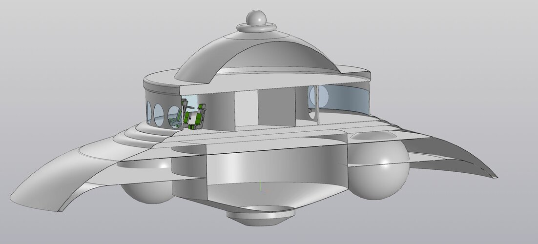
The smallest known German dish with a diameter of 25 m. The weight of the structure (duralumin) is 80 tons. The crew is 12 people. There are three layers of screens under the floor of the passenger compartment that save the crew from electromagnetic radiation. In the center is a generator and three anti-gravity emitters.
Attachments
Has there ever been a disk shape flying animal? Why do they all have wings?
But not to forgett, even the public broadcasting (yes those without any fakenews...) have been promoting flying saucers presented by a mad scientist...
View: https://www.youtube.com/watch?v=rbqeRh1mjlU&ab_channel=Hibernate2012
But not to forgett, even the public broadcasting (yes those without any fakenews...) have been promoting flying saucers presented by a mad scientist...
Scott Kenny
ACCESS: Above Top Secret
- Joined
- 15 May 2023
- Messages
- 6,179
- Reaction score
- 5,032
In the case of the XF5U, it was superseded by jet engines and turboprops weren't there yet. For giving a small ship a VTOL or STOVL aircraft that has much greater speed than a helicopter, it's still one of the best available designs. Crud, if you look at the general planform of the DARPA TERN proposals, they're Salmon/Pogos all over again.The mere fact that lenticular aerospace vehicle designs have been proposed, discussed, or even occasionally tested before does not validate their superiority, since evidently they have never been adopted for any actual mainstream aerospace systems.
That would depend on the individual reports on a case by case basis.
A little history. In 1947, flying disc reports were being evaluated at Wright Field. These included reports coming in from civilians and military personnel. A series of Projects to handle civilian reports soon began: Project Saucer which was changed to Project Sign, followed by Project Grudge and then Project Blue Book. No explanations were forthcoming.
For military personnel, the situation was much different. Along with CIRVIS (Communication Instructions for Reporting Vital Intelligence Sightings), there was JANAP or Joint Army Navy Air Publication directives. This applied across North America. Military personnel were prohibited from reporting what became known as UFO sightings. This was followed by restrictions on commercial pilots. In other words, those trained to navigate the air, and with a background in common and not so common, aerial anomalies, could say little, if anything, about sightings, even at close range.
Meanwhile, Lockheed also did research into a circular aircraft design.
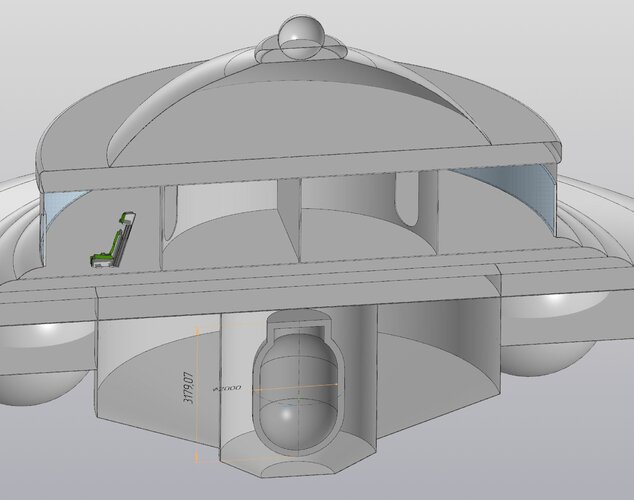
paralay
ACCESS: Top Secret
Let's assume a nuclear reactor as an energy source. The diameter is 2 meters, the height is 3 meters. The ball from above is probably not a radar, but a braking engine and at the same time a device for entering four-dimensional space
It is required to estimate the power of such a reactor
It is required to estimate the power of such a reactor
Attachments
- Joined
- 6 November 2010
- Messages
- 4,240
- Reaction score
- 3,185
If this is still about
Fantasy?
... I have a hard time swallowing the notion that WW2 German engineers were contemplating nuclear-powered (!) flying saucers.The smallest known German dish
Fantasy?
Dilandu
I'm dissatisfied, which means, I exist.
Newsflash: our space is four-dimensional. Don't forget the time.The ball from above is probably not a radar, but a braking engine and at the same time a device for entering four-dimensional space
Dilandu
I'm dissatisfied, which means, I exist.
Pure and clear. In reality, the only disk-shaped aircraft Germans actually build during WW2 as a small propeller-driven Sack AS-6, build from parts of worn-out fighters. And it wasn't even able to fly, merely hop... I have a hard time swallowing the notion that WW2 German engineers were contemplating nuclear-powered (!) flying saucers.
Fantasy?
The smallest known German dish with a diameter of 25 m. The weight of the structure (duralumin) is 80 tons. The crew is 12 people. There are three layers of screens under the floor of the passenger compartment that save the crew from electromagnetic radiation. In the center is a generator and three anti-gravity emitters.
That's Adamski's flying saucer.
View: https://twitter.com/marianotomatis/status/509112716016246784
Yet N-1 used them...had the engines/electronics been a bit better it could have been successful.No, it doesn't work. Having a tanks and an external skin is just wasted (space)
I don't buy antigravity tech now let alone in the 1940s.
Dilandu
I'm dissatisfied, which means, I exist.
Considering that gravity is the weakest of four known fundamental interactions - about 10e38 times weaker than electromagnetic - it's a safe bet that even if antigravity tech is possible, it would have rather limited use, mostly for highly specific purposes. The flying car with photon lifters (300 Mwt per 1H) would still be 38 orders of magnitude more economical than anti-gravity one.I don't buy antigravity tech now let alone in the 1940s.
A. no, it didn't. Because it had spherical tanks, it had very long intertanks.Yet N-1 used them...had the engines/electronics been a bit better it could have been successful.
b. It had a poor mass fraction because it. That and the use of hydrogen was why the Saturn V could send more to the moon.
Similar threads
-

-

-

-
-
 Really Top Secret Projects (Ben Rich remark to Jim Goodall)
- Started by flateric
- Replies: 245