FATE and ICE studies

Does anyone know whether the studies showed that you could achieve comparable control / roll rates etc. with a tailless design if you got the fly by wire software right or were there performance trade offs?

Obviously there are big drag and stealth advantages so it seems like a obvious next step in fighter design if you can achieve comparable maneuverability.
 
Sundog said:
Hmmm, I think it looks like a horrible reentry vehicle, but an excellent tailless fighter. ;)

It's nice being able to see the bottom and the inlet design.

I wonder if the seller acquired the model in an estate sale. It's entertaining sometimes what these sellers believe the model to be.
 
phrenzy said:
Does anyone know whether the studies showed that you could achieve comparable control / roll rates etc. with a tailless design if you got the fly by wire software right or were there performance trade offs?

Obviously there are big drag and stealth advantages so it seems like a obvious next step in fighter design if you can achieve comparable maneuverability.

My understanding is that the X-36 had an amazing roll rate. I don't recall the exact number at this time, though.
 
Effective Design of Highly Maneuverable Tailless Aircraft -Richard Colgren and Robert Loschke ( Lockheed Martin)

https://www.scribd.com/doc/274449281/Colgren-Loschke-Lockheed-Tailless-Aircraft

On YTV

Given the difficulty of finding suitable aerodynamic yaw controls, the designer of low aspect ratio tailless aircraft is usually forced into considering the use of yaw thrust vectoring (YTV) as a yaw control device. The primary advantage of YTV is that it retains its effectiveness in flight regimes where conventional aerodynamic yaw controls are ineffective, for example, at low airspeeds or high . YTV is also very effective in controlling the yawing moment due to an engine failure on a multi-engine aircraft having the engines mounted close to the centerline. The YTV can force the thrust vector of the remaining engine or engines to pass very close to or through the c.g. This eliminates, or at least minimizes, the yawing moment created by the failed engine.

There are two primary disadvantages of YTV. First, the engine power setting and the limited angular deflection of the thrust vector limits the total control power. Second, except for mechanical panels that are inserted directly into the exhaust jet, methods that have been developed and tested to change the direction of the engine’s exhaust typically have a lower bandwidth capability than conventional aerodynamic effectors.
Because aircraft are typically optimized to reduce the aerodynamic drag to a minimum, and the removal of conventional vertical tails reduces drag still further, the thrust required for cruise is also minimized. Combined with the limited angular deflection of the thrust vector, the yaw control power attainable with YTV is sometimes severely limited. In any case, the aircraft must remain under control at any point within the permissible flight envelope for any possible engine power setting. This includes the case of the total loss of engine thrust due to compressor stalls during high- maneuvers, fuel starvation due to fuel system malfunctions, etc. Control must be maintained for some period of time sufficient for engine restart or the clearance of malfunctions. Consequently, some aerodynamic yaw control device must be available to provide the necessary control power until the YTV can be restored.
Depending on how the thrust vectoring mechanism is implemented, the attainable bandwidth for YTV is typically limited to approximately 1.0–1.5 Hz for deflections in the range of plus or minus 50% of maximum deflection. This is entirely satisfactory for use as steady-state yaw trim devices or for slow, gentle maneuvers. However, it is not fast enough to provide the good lateral-directional handling qualities required for the rapid, large-amplitude maneuvers used by fighter aircraft. Once again, some high-bandwidth aerodynamic yaw control device is required to supplement the YTV.
For fighter aircraft with a high thrust-to-weight ratio, the use of thrust vectoring is beneficial for rapid, large-amplitude maneuvers at speeds up to about 250 kt calibrated airspeed. This corresponds to the upper left-hand corner of the Mach–altitude flight envelope. Fortunately, this is the part of the flight envelope where very high- maneuvering takes place and where the engine would typically be operating at maximum power settings. In the case of the F-22, the use of thrust vectoring is of most benefit in the pitch axis, where it is used to prevent pitch up during high- rolls. This unloads the horizontal tails and allows them to be used as both roll and yaw effectors to provide high rolling performance [2–4]. If the aircraft is designed to have neutral aerodynamic stability, the aerodynamic moments to be overcome during maneuvers are reduced to a minimum. Then thrust vectoring can be used for quasi-steady-state low-amplitude maneuvering throughout the flight envelope. For rapid, large- amplitude maneuvering at high airspeeds, aerodynamic control effectors must be used. Their effectiveness continues to increase as the square of the airspeed.
It is seen that YTV can be a useful yaw control for a tailless aircraft, but it can never be the primary or only yaw control device. Some type of aerodynamic control device is still always required, because control must be maintained even if all thrust is lost due to engine failure.

Summary and Conclusions

The design of a supersonic air superiority fighter without vertical tails is possible. To accomplish this, some traditional fighter aircraft features will almost certainly have to be abandoned. New technologies will also need to be substituted. For example, the conventional forward-mounted bubble canopy with its large forward side area must be made significantly smaller or eliminated entirely.

An F-15B-based simulation was used to demonstrate the destabilizing effects of these features without traditional vertical stabilizers. A “virtual reality” cockpit, incorporating sensor fusion to provide situational awareness for the pilot, could replace the bubble canopy. Many other novel features must be incorporated into the airframe to make it safe to fly and yet have good mission capability, including nontraditional control effectors. A number of new aerodynamic yaw effectors have to be investigated, developed, and incorporated into the airframe design so that the FBW FCS can provide good handling qualities. These will need to be evaluated using CFD codes, wind-tunnel tests, and motion-based handling qualities simulators. Eventually, these will need to be verified in flight.

The combination of so many new features increases the development risk. It requires a thorough analysis and a detailed simulation program to be initiated very early in the conceptual design phase. The cost of correcting errors at this stage is about 1% of the cost of fixing them in the fligh-test stage. This justifies the up-front costs associated with the wind-tunnel testing required to provide a good aerodynamic database. The mathematical models used in the simulation must be rigorous. They must include second-order effects that can be critical to the understanding of the potential interactions between the many novel design concepts. Uncertainties in the aerodynamic characteristics must be systematically studied to be certain that there is an adequate design margin before proceeding into detail design. The most important failure modes should be simulated and system redundancy requirements defined. Finally, an evaluation of concept feasibility must be made. The ultimate objective of the concept definition phase is the accurate identification of the real penalties in weight, complexity, and costs associated with the removal of the vertical tails. This is necessary to avoid modifications to the design concept in later phases of the program, resulting in cost overruns and schedule delays
 
Demonstration of Fluidic Throat Skewing for Thrust Vectoring in Structurally Fixed Nozzles - Lockheed Martin Aeronautics Company

https://www.scribd.com/doc/274451266/Demonstration-of-Fluidic-Throat-Skewing-for-Thrust-Vectoring-in-Structurally-Fixed-Nozzles?secret_password=6mN2y4CLrZBrvuAlo5Rl
 
Good stuff.
It seems like one of the advantage of yaw vectoring, namely the elimination of parasitic drag and weight of aerodynamic yaw effectors, cannot be fully realized lest control be lost in the event of engine failure. Maybe you can still use smaller surfaces and supplement them with yaw vectoring? In that case, in non-maneuvering flight, yaw vectoring could be used and the aerodynamic control surfaces kept undeflected to improve RCS. Of course you would have to revert to using both where high pitch/yaw rates were required.
 
AeroFranz said:
Good stuff.
It seems like one of the advantage of yaw vectoring, namely the elimination of parasitic drag and weight of aerodynamic yaw effectors, cannot be fully realized lest control be lost in the event of engine failure. Maybe you can still use smaller surfaces and supplement them with yaw vectoring? In that case, in non-maneuvering flight, yaw vectoring could be used and the aerodynamic control surfaces kept undeflected to improve RCS. Of course you would have to revert to using both where high pitch/yaw rates were required.

Problem is that single-engine aircraft still have the occasional flame-out. Then what do you do?
 
AeroFranz said:
Good stuff.
It seems like one of the advantage of yaw vectoring, namely the elimination of parasitic drag and weight of aerodynamic yaw effectors, cannot be fully realized lest control be lost in the event of engine failure. Maybe you can still use smaller surfaces and supplement them with yaw vectoring? In that case, in non-maneuvering flight, yaw vectoring could be used and the aerodynamic control surfaces kept undeflected to improve RCS. Of course you would have to revert to using both where high pitch/yaw rates were required.


My understanding was that on the X-36, the split ailerons provided the static stability in yaw and the TV provided the dynamic stability in Yaw. Don't quote me on it, it's been a long time since the engineers on that program gave their lecture. However, if that is the case, it would seem to me that the aerodynamic flight controls could take over some of the dynamic stability, it just wouldn't be as powerful. As long as you have two separate flight control surfaces on each side of the trailing edge of the wing, it would seem to me you could maintain enough control to get a vehicle down safely.
 
https://www.flightglobal.com/news/articles/lockheed-martin-has-eyes-on-fate-designs-1474/ (Jan 97')

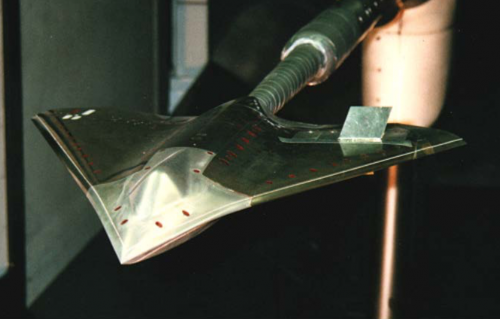
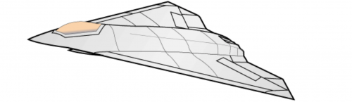
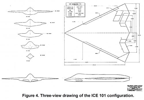
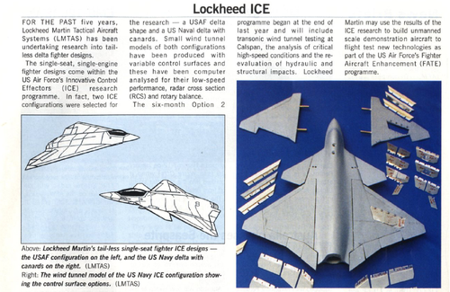
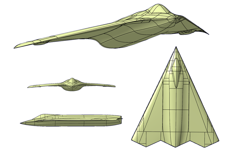
Lockheed Martin plans to offer a tailless-delta design for the US Air Force's planned Fighter Aircraft Enhancement (FATE) programme to build pilotless demonstrators to flight-test new technologies. The company has been working on the tailless-fighter design since 1991, most recently under the Air Force's Innovative Control Effectors (ICE) research programme. Produced by Lockheed Martin Tactical Aircraft Systems of Fort Worth, Texas, the design, dubbed Configuration 101 (http://www.secretprojects.co.uk/forum/index.php/topic,3547.msg190000.html#msg190000) , is for a single-seat, single-engined fighter with a 65 degree sweep delta planform

https://www.flightglobal.com/news/a...r-demonstrator-study-contracts-awarded-11408/ (July 97')

FOUR COMPANIES HAVE been awarded three-month, $300,000 US Air Force contracts to begin work on the Future Air-craft Technology Enhancement (FATE) unmanned, subscale fighter demonstrator. Under the study contracts, Boeing, Lockheed Martin, McDonnell Douglas and Northrop Grumman will determine which aerodynamic, flight-control, subsystem and structures technologies should be incorporated in the FATE vehicle for flight testing around 2001
 
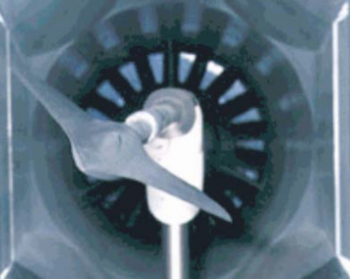
Innovative Control Effectors (pdf). These are the same Lockheed designs shown up thread, but with more detail on the structure and the effector schemes tested.

BTW, thanks BIO for the references regarding the X-36's controls.
 
A Tailless Fighter Aircraft Model for Control-Related Research and Development

Niestroy, M.A1, Dorsett, K.M.2, and Markstein, K.3
Lockheed Martin Aero, Fort Worth, TX, 76101

https://arc.aiaa.org/doi/abs/10.2514/6.2017-1757
 

Attachments

  • Lockheed IR&D001.png
    Lockheed IR&D001.png
    666.9 KB · Views: 760
  • Lockheed IR&D 005.png
    Lockheed IR&D 005.png
    668 KB · Views: 723
  • Lockheed IR&D ICE.png
    Lockheed IR&D ICE.png
    191.7 KB · Views: 797
...
 

Attachments

  • LM ICE 101.jpg
    LM ICE 101.jpg
    335 KB · Views: 701
Last edited:

Similar threads

Back
Top Bottom