- Joined
- 29 July 2009
- Messages
- 1,770
- Reaction score
- 2,479
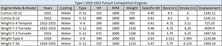
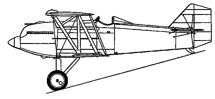
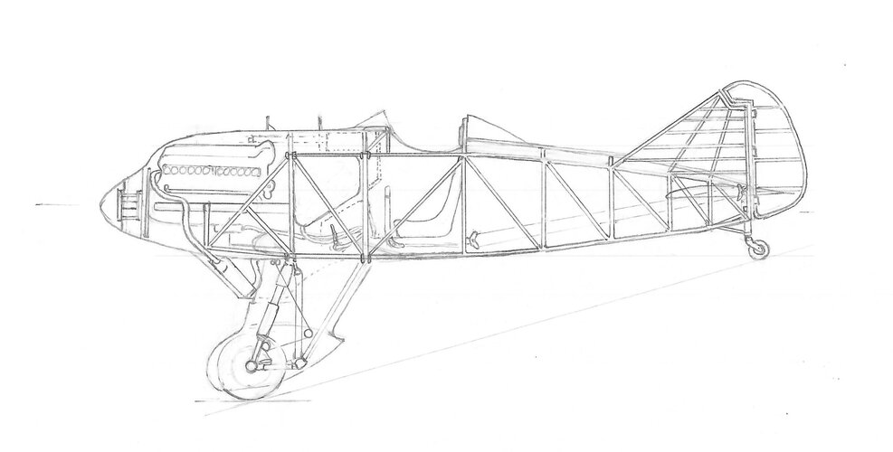
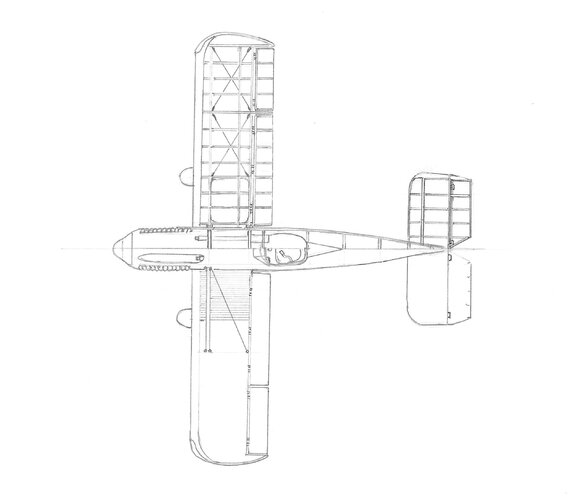
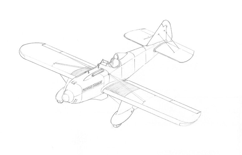
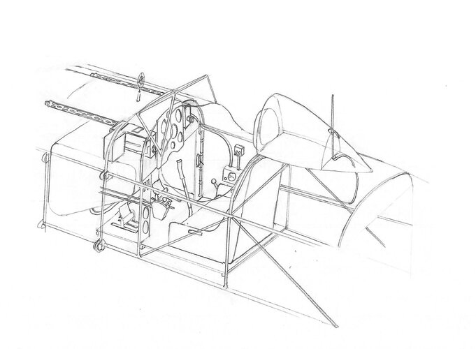
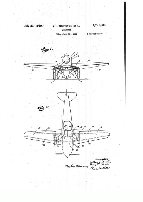
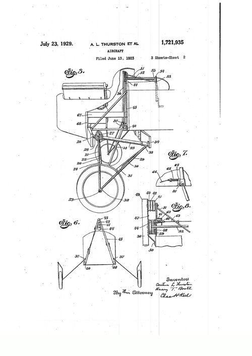
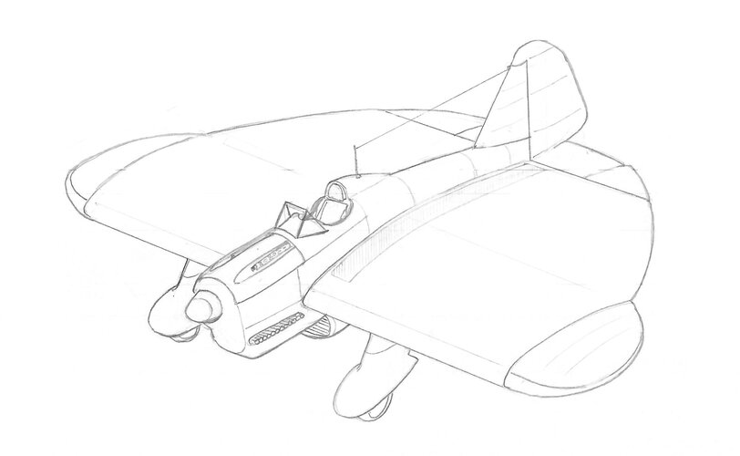
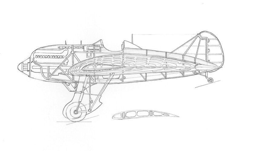
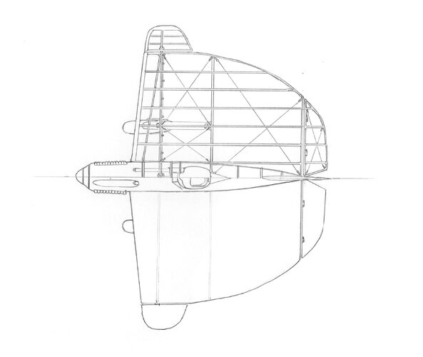
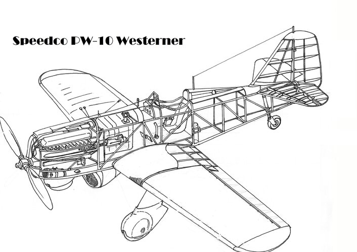
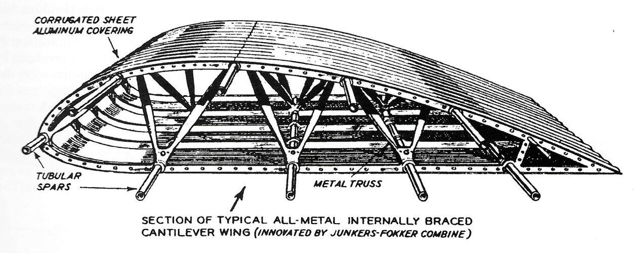
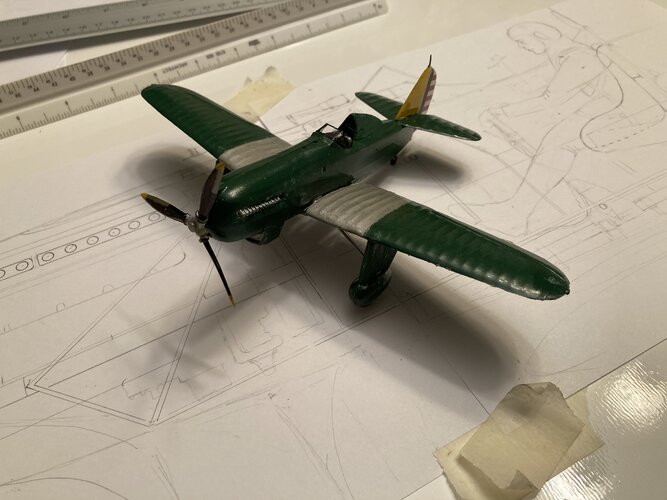
Using 1919 aircraft design examples, era engines, weapons, and early post-WWI aircraft construction techniques, an interesting exercise can be made in responding to the 1919 US Army Air Service requirements for a Type I water cooled pursuit aircraft. The original specifications are listed below. Its competition was the Engineering Division's PW-1, Loening PW-2, Orenco PW-3, Gallaudet PW-4, Fokker's PW-5/PW-6/PW-7, Curtis PW-8, and Boeing's PW-9, which were developed between 1919-1923. Using these and other aircraft for historical weight fractions, NACA airfoil data, Woodhouse's 1919 publications on aircraft design and construction, and various encyclopedias on era engines and systems, a preliminary design can be created.
Type I Requirements:
Single Seat Day Pursuit Aircraft
Water cooled engine
Maximum speed of 145 mph at 15,000 ft.
Climb to 20,000 ft. in 21 minutes
Service Ceiling of 23,750 ft.
Endurance of 2.5 hours at 15,000 ft., with an additional half hour at sea level
Useful load of 525 lbs.
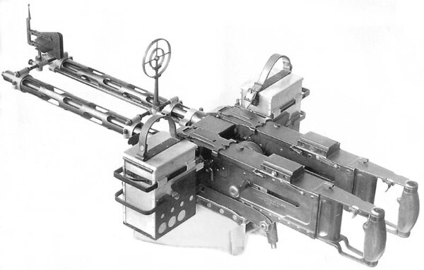
Fixed armament of .30 caliber or .50 caliber machine guns
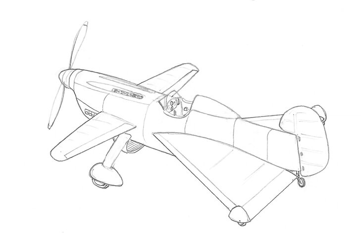
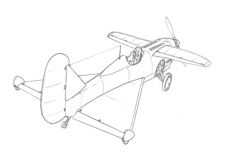
Conceptual design effort:
To understand and respond to the Type I mission requirements
To use state-of-the-art technologies for the 1919-1923 time period as practical as possible
To find creative ways to integrate the technologies to make it a formidable and sustainable design
To consider the materials, manufacturing processes and design tools used in the same period
From this preliminary design effort the hope is to generate:
Configuration
Weight estimation
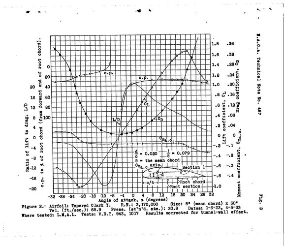
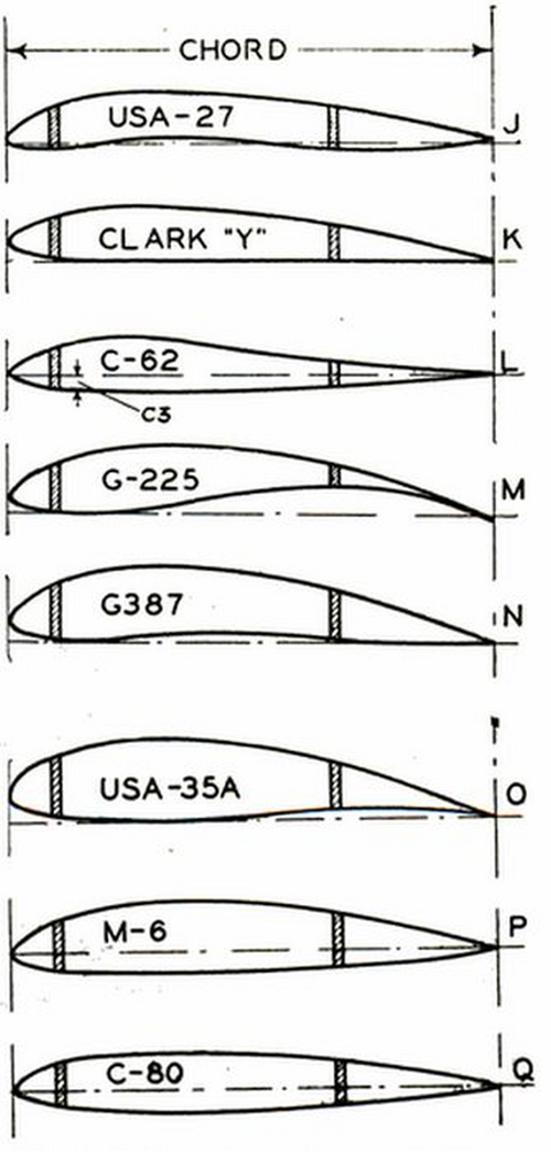
Airfoil selection
Wing loading and thrust loading
Wing design
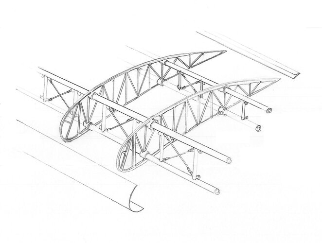
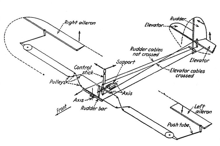
Fuselage, landing gear, and control surface design
System and armament placement
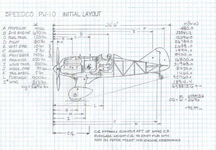
CG Calculations
Performance estimates
Preliminary stability data
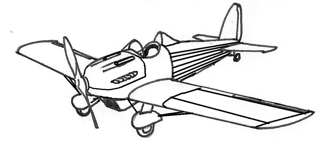
For fun, the aircraft company name is SPEEDCO for Secret Projects-Forum Engineering Evaluation and Design Company and it's designation is PW-10.
Type I Requirements:
Single Seat Day Pursuit Aircraft
Water cooled engine
Maximum speed of 145 mph at 15,000 ft.
Climb to 20,000 ft. in 21 minutes
Service Ceiling of 23,750 ft.
Endurance of 2.5 hours at 15,000 ft., with an additional half hour at sea level
Useful load of 525 lbs.
Fixed armament of .30 caliber or .50 caliber machine guns
Conceptual design effort:
To understand and respond to the Type I mission requirements
To use state-of-the-art technologies for the 1919-1923 time period as practical as possible
To find creative ways to integrate the technologies to make it a formidable and sustainable design
To consider the materials, manufacturing processes and design tools used in the same period
From this preliminary design effort the hope is to generate:
Configuration
Weight estimation
Airfoil selection
Wing loading and thrust loading
Wing design
Fuselage, landing gear, and control surface design
System and armament placement
CG Calculations
Performance estimates
Preliminary stability data
For fun, the aircraft company name is SPEEDCO for Secret Projects-Forum Engineering Evaluation and Design Company and it's designation is PW-10.
Last edited: