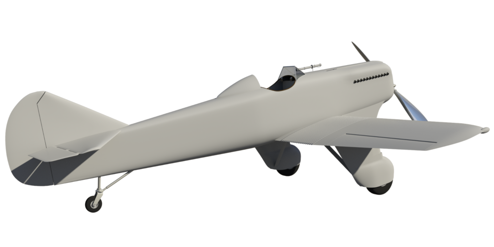
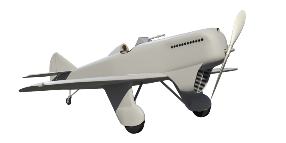
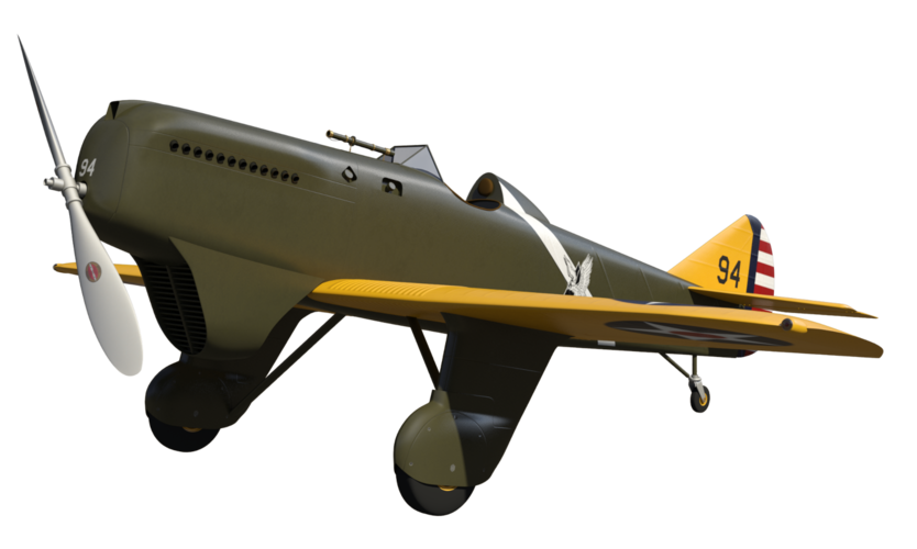
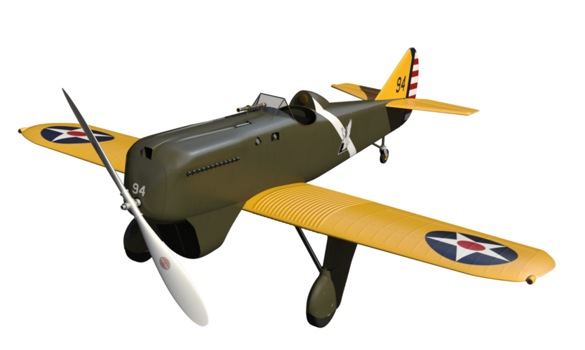
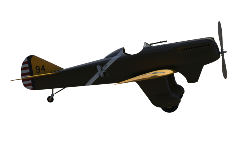
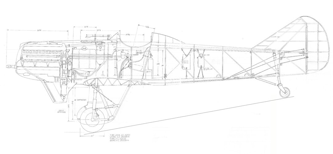
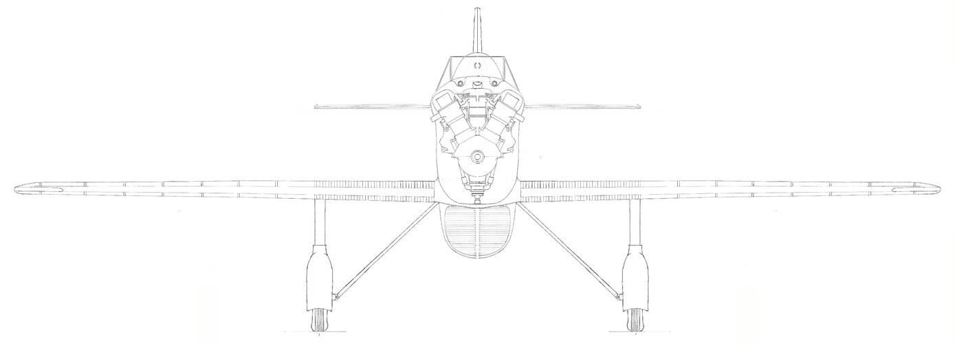
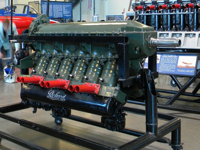
I'd concentrate as much weight as close to the center of mass as possible by going engine behind the pilot. Main wing above the engine and behind the pilot. The engine block would offer the pilot a bit of protection from rear attacks. The radiator would be coils running inside the leading edge of the main wing.
The nose would contain the guns, preferably rigged to fire separately. Rationing bullets was important in that era. A nose-mounted spotlight in-line with the guns would help the pilot judge nose aim. This could be helpful in dusk and dawn attacks. While maybe not as useful in air-to-air, it would give the pilot a sense of aim during strafe runs. Having a diffuser that can get flipped in and out of the light would aid in wide-angle vision.
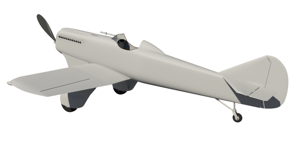
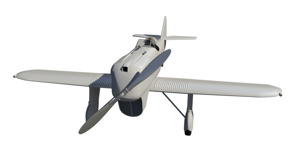
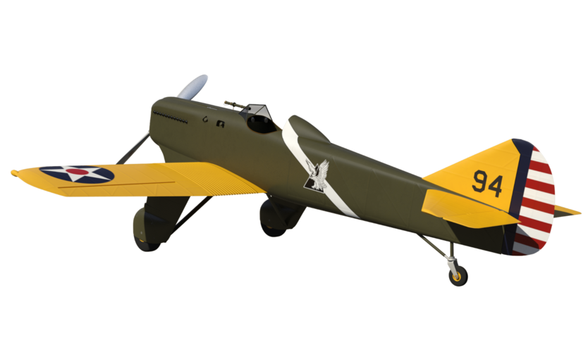
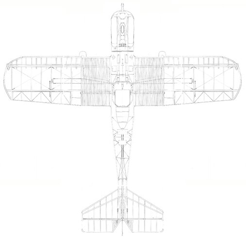
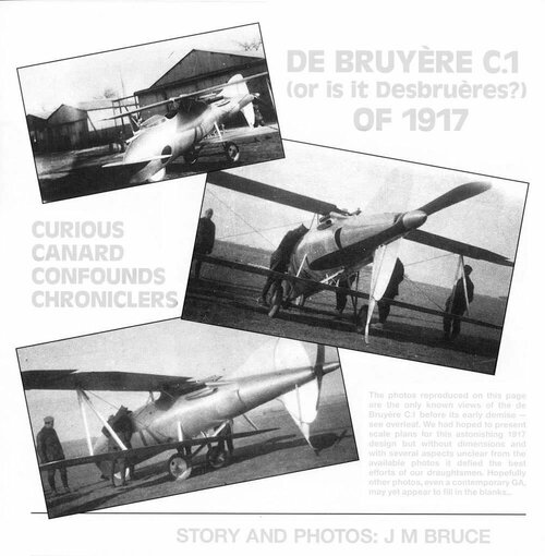
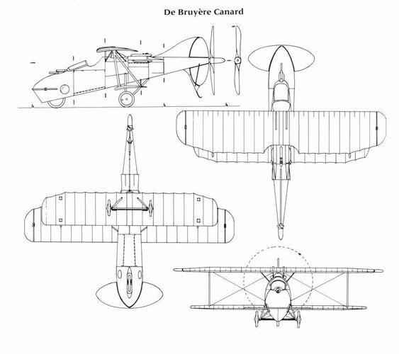
There would be a stiff, all-moving canard plane in the front of the cose section, and a stub wing in the back, much smaller than the main wing. The stub wing would have small trailing counter-flaps. The combination of the two would act similar to a conventional tail. Pitch of the canard and trailing stub wing flaps would be controlled by the pilot's feet and a small wheel in front of pilot, one for each side, to dial in trim. The pedals that control the canard would be far apart, leaving space for a second pedal for each foot in between for rudder controls. The rudders would be on the main wings and linked to rudder vanes that are washed by the prop, like on an airboat.
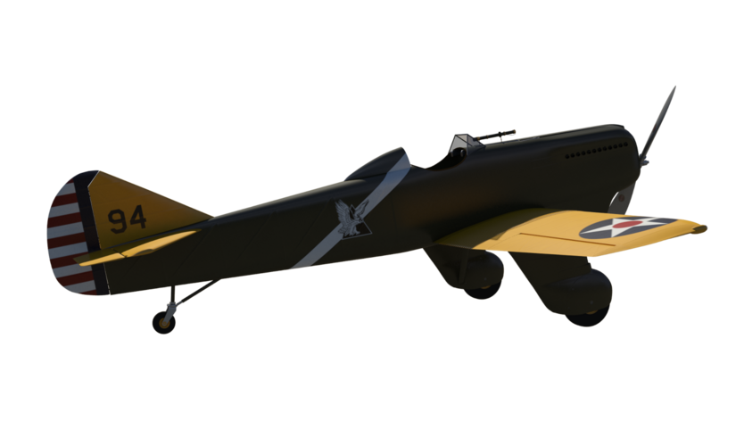
Вместо одной палки я хочу по одной для каждой руки и расположенной по бокам кокпита. К каждой рукоятке рукояти будут прикреплены спусковые крючки, связанные с пистолетом с той же стороны. Я бы управлял закрылками с помощью стиков. Потянув назад или толкнув вперед, закрылок будет перемещаться вверх и вниз по крылу. Однако рычаги управления будут связаны торсионной пружиной, что позволит одной ручке управлять обоими закрылками, что может быть полезно в аварийной ситуации, например, при разрыве тяги ручки управления. Пружина кручения позволяла скручивать закрылки друг от друга для крена, но (из-за напряжения пружины) пыталась выровняться по мере ослабления скручивающих сил. Палки также позволяли бы ограниченное движение из стороны в сторону, что помогло бы придать пружине скручивание, чтобы облегчить маневры с перекатыванием. Палки также будут связаны с задним набором горизонтальных лопастей, омываемых винтом. При максимальном вращении винта пилот получит значительную обратную связь в своих органах управления. Все это сделало бы возможным базовые маневры, выполняемые одной рукой, что, я считаю, было бы важно.
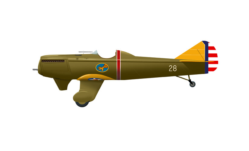
И чуть не забыл, весь мой маркетинг будет сосредоточен на европейских партнерах. Ни за что, черт возьми, армия на самом деле не использовала бы эту конструкцию с обратной задницей. Думаю, ими могут заинтересоваться шведы, британцы, французы и испанцы.

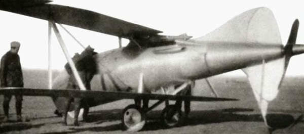
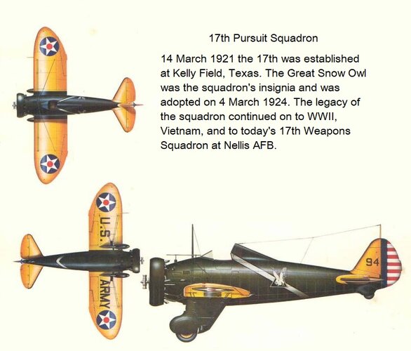
")