- Joined
- 29 July 2009
- Messages
- 1,518
- Reaction score
- 1,512
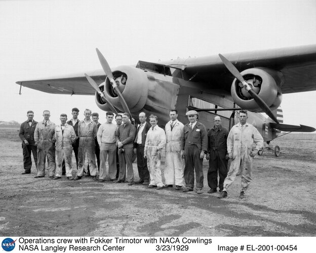
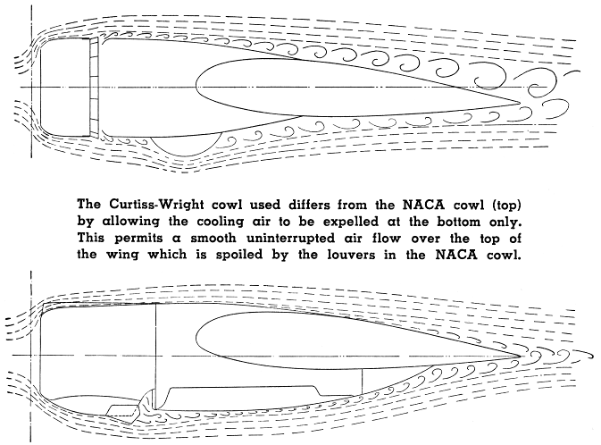
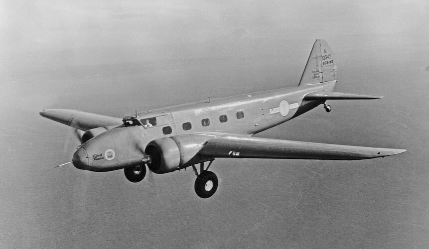
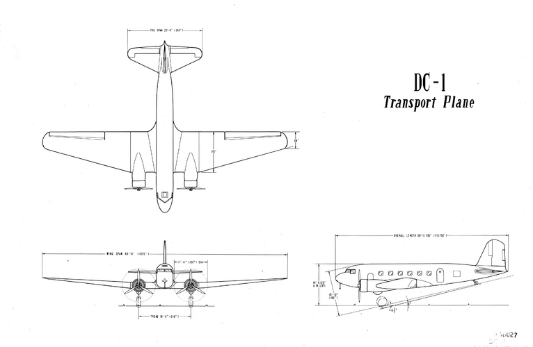
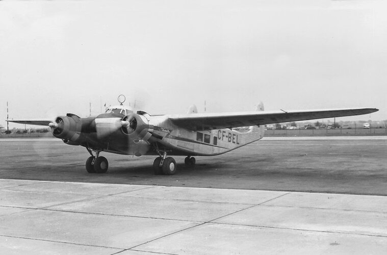
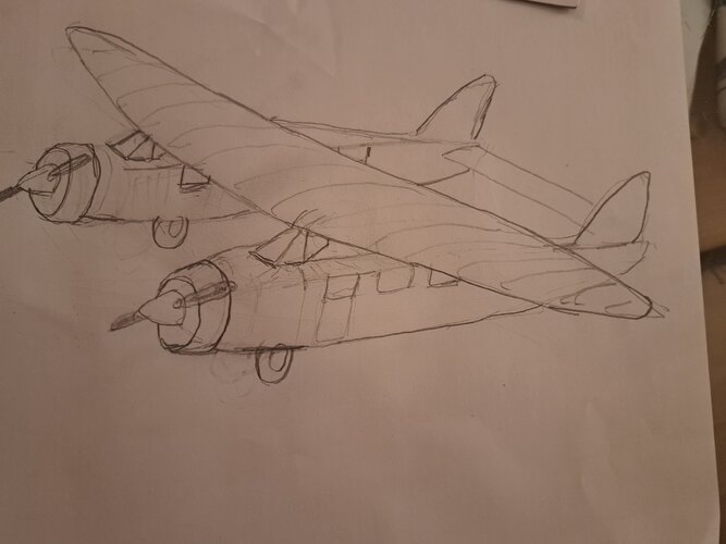
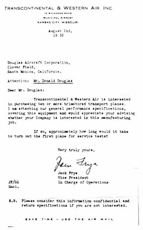
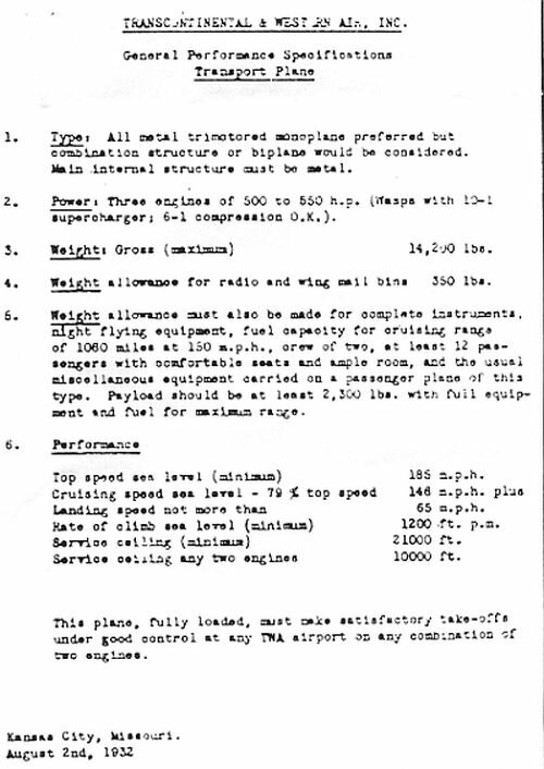
In a now famous letter sent from Transcontinental and Western Airlines (TWA) executive Jack Frye to Donald Douglas of the Douglas Aircraft Corporation (provided below), Frye attempted to buy the modern Boeing 247, which was a state-of-the-art airline design that ushered in all metal construction, retractable landing gear, and NACA designed cowlings, however United Airlines secured a deal with Boeing that would tie up production of the B-247 until 60 aircraft were built. This gave United a competitive edge over all of the other airlines who were still flying the biplane Curtiss Condors (American Airlines) and Boeing B-80 and the slow Fokker and Ford trimotors (Eastern, American and TWA). The letter from Frye requested a trimotor design monoplane that could seat 12 passengers and cruise in excess of 145 mph. Douglas went to work on designing an aircraft that could meet Fryes expectations, but instead developed a design that would go on to become the legendary DC-3. (The DC-1 being a prototype of the DC-2 and its DST version, the DC-3)
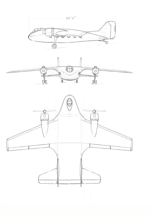
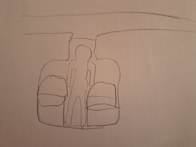
As a fun exercise, using historical data and references, to design an aircraft that meets or exceeds Jack Frye's request for an airliner that can compete against the Boeing 247 and possibly even to exceed the performance of the DC-1/D-2 using era available technologies. This is strictly a fun exercise in conceptual and preliminary design to provide the opportunity to converse, research and design a classic airliner of the early 1930s, an era know for it's luxury airline travel and pioneering aviation achievements.
As a fun exercise, using historical data and references, to design an aircraft that meets or exceeds Jack Frye's request for an airliner that can compete against the Boeing 247 and possibly even to exceed the performance of the DC-1/D-2 using era available technologies. This is strictly a fun exercise in conceptual and preliminary design to provide the opportunity to converse, research and design a classic airliner of the early 1930s, an era know for it's luxury airline travel and pioneering aviation achievements.
Attachments
Last edited: