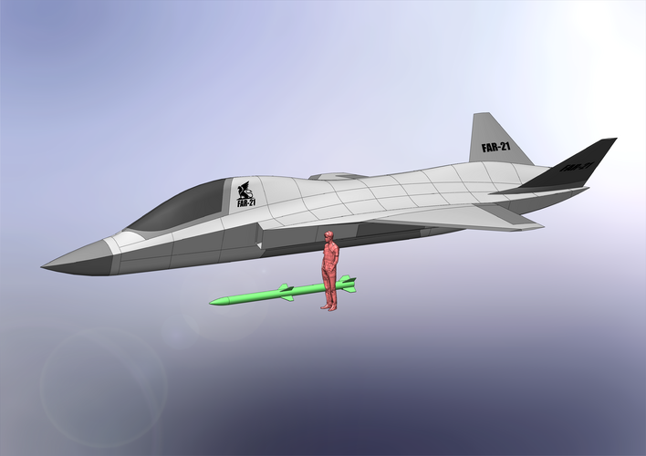
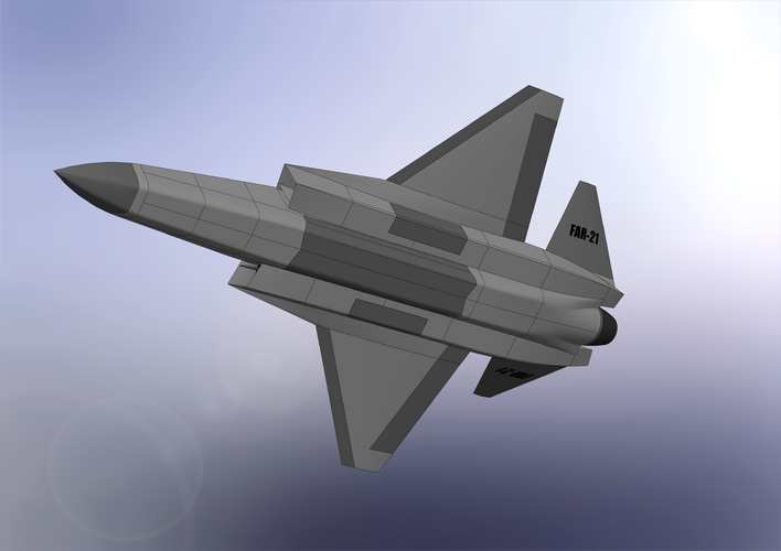
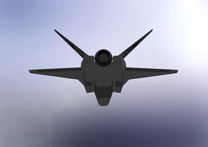
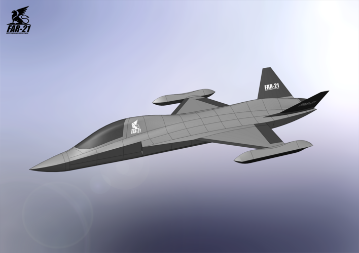
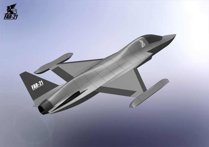
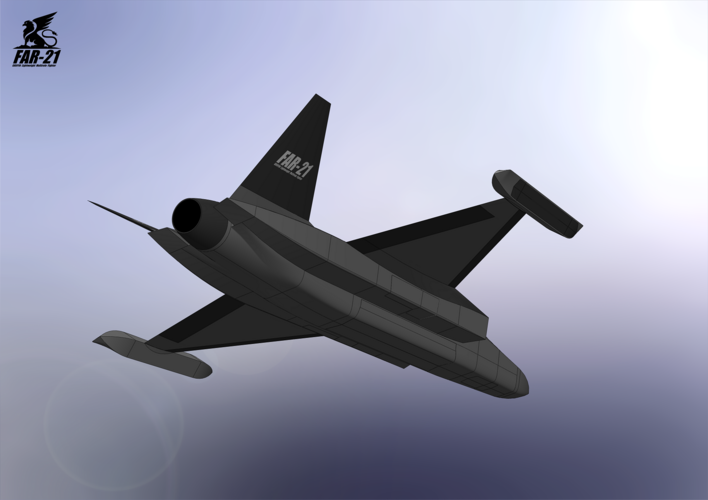
When will you submit the drawing?Here we go, the FAR-21 Griffin is born. One can guess what FAR stands for")

You are using an out of date browser. It may not display this or other websites correctly.
You should upgrade or use an alternative browser.
You should upgrade or use an alternative browser.
Design Challenge: Lightweight Multirole Fighter (LMF)
- Thread starter VTOLicious
- Start date
Would spine across the fuselage from cockpit to the engine better than a hump above the engine? Also it will has benefit for more fuel.Thank you. I like the F-20 analogy.Superb work. A true son of the mighty F-20 Tigershark.
If you want it to more closely follow the area rule, you'll certainly have to replace the aft positioned ruddervator with a vertical (think M2K) or fill the gap b/w the wing trailing edge with a section increase of some sort.
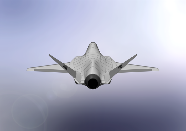
In regards of area rule: Have a close look. It actually has a "hump" to fill the gap between wing an V-tail.
View attachment 672398
Last edited:
- Joined
- 24 November 2008
- Messages
- 1,549
- Reaction score
- 2,612
I have to tweak the 3D model a little more. In particular the rear, where the fuselage meets the nozzle. Not entirely happy with the current geometry.When will you submit the drawing?Here we go, the FAR-21 Griffin is born. One can guess what FAR stands for
- Joined
- 24 November 2008
- Messages
- 1,549
- Reaction score
- 2,612
Nope. The intention is drag reduction at transonic speeds. See Whitcomb area rule: https://en.wikipedia.org/wiki/Area_ruleWould spine across the fuselage from cockpit to the engine better than a hump on above the engine? Also it will has benefit for more fuel.Thank you. I like the F-20 analogy.Superb work. A true son of the mighty F-20 Tigershark.
If you want it to more closely follow the area rule, you'll certainly have to replace the aft positioned ruddervator with a vertical (think M2K) or fill the gap b/w the wing trailing edge with a section increase of some sort.
In regards of area rule: Have a close look. It actually has a "hump" to fill the gap between wing an V-tail.
View attachment 672398

What level of design detail are you working towards?
Are you gonna design/include gear/control surfaces/other systems?
How are you gonna calculate the fuel space?
I think that you could reach a pretty highly detailed design fairly easily through this method!
You might just have inspired me to do something similar...
Are you gonna design/include gear/control surfaces/other systems?
How are you gonna calculate the fuel space?
I think that you could reach a pretty highly detailed design fairly easily through this method!
You might just have inspired me to do something similar...
- Joined
- 24 November 2008
- Messages
- 1,549
- Reaction score
- 2,612
What level of design detail are you working towards?
Are you gonna design/include gear/control surfaces/other systems?
How are you gonna calculate the fuel space?
I think that you could reach a pretty highly detailed design fairly easily through this method!
You might just have inspired me to do something similar...
The level of detail is dependent on time and effort I can (or wanna) spend on this
In general I wanna keep it on a conceptual level and add only items which are of importance for the internal arrangement. I may add landing gears next. One of the main tasks is to find sufficient space for at least 2800 liters of fuel. To do so I'm gonna model fuel tanks (solid 3d objects) and measure the volume of each one. 27 m³ is the estimated aircraft volume requirement.
Great if I have inspired you! Go for it! I would love to see someone come up with another LMF concept model.
Last edited:
- Joined
- 19 July 2016
- Messages
- 4,279
- Reaction score
- 3,462
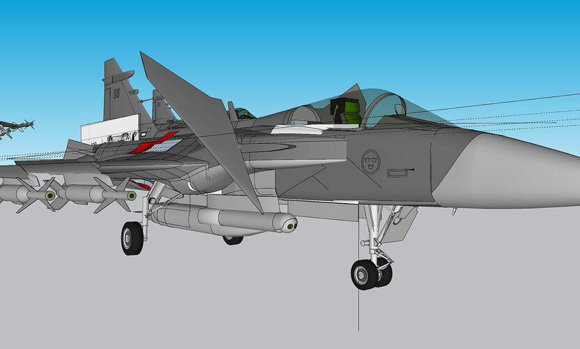
I am playing around with a Gripen with rear intakes. Four in all which will partially move into and out of the airframe. I know but I got bored and next thing I know there is a Gripen facing surgery. Think kindly of the poor beast.
- Joined
- 24 November 2008
- Messages
- 1,549
- Reaction score
- 2,612
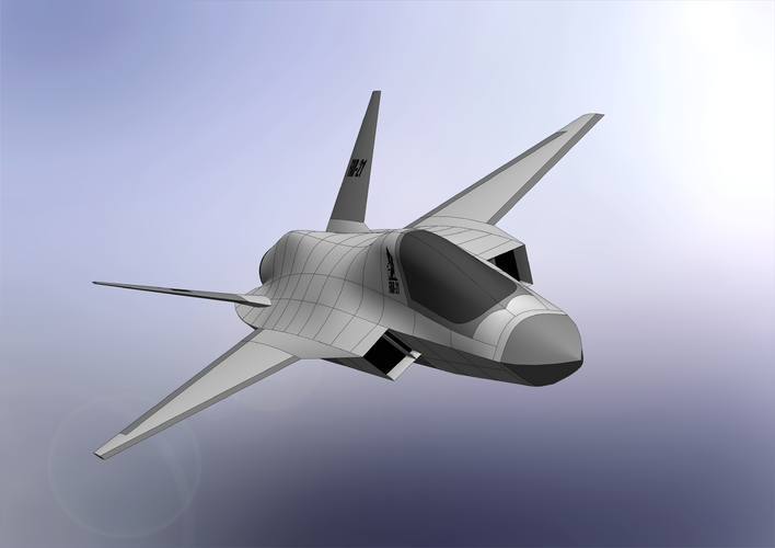
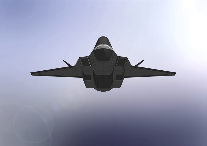
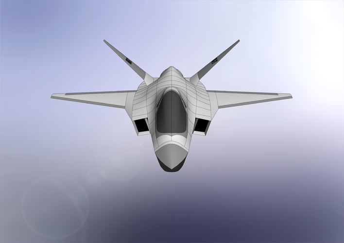
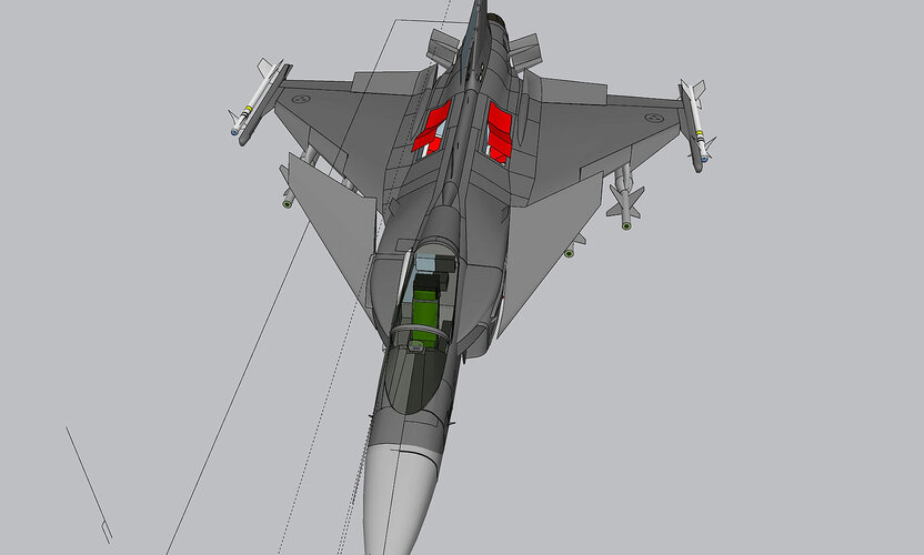
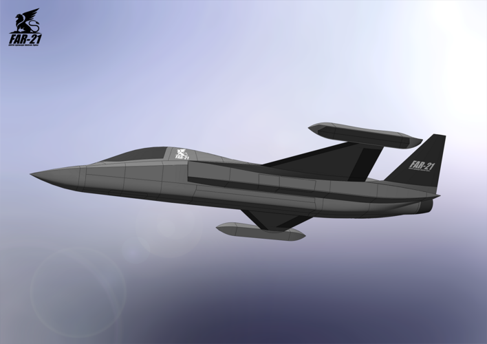
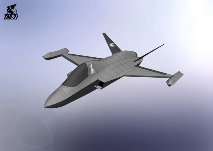
Canopy reworked, rear section reworked, wing shifted 0,3 m aft and I've tweaked the 3d model towards 27 m³ total volume,... some "panel lines" added for better visualization of the fuselage shape.
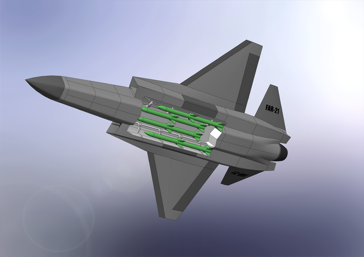
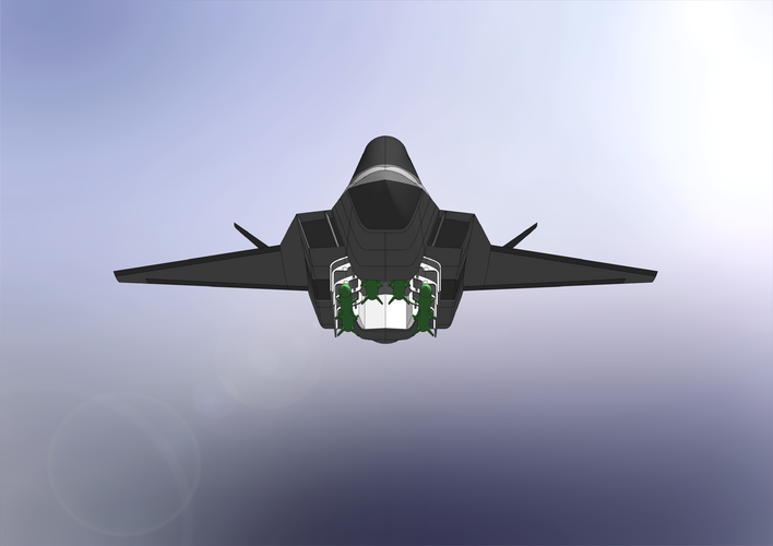
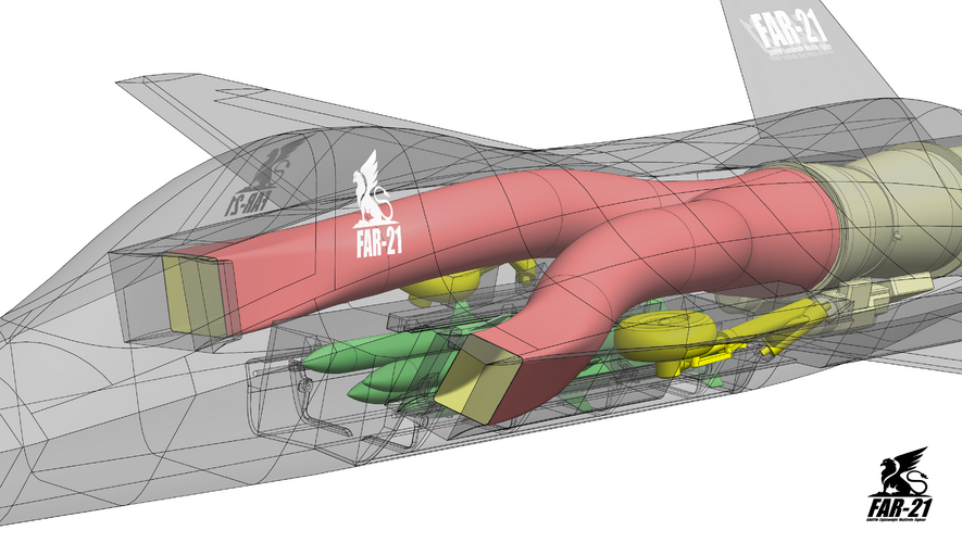
And the IWB is fully integrated now! Including moveable doors with AIM-120 attached to it.
Next task: Landing gears!
And the IWB is fully integrated now! Including moveable doors with AIM-120 attached to it.
Next task: Landing gears!
Attachments
- Joined
- 24 November 2008
- Messages
- 1,549
- Reaction score
- 2,612
- Joined
- 21 May 2006
- Messages
- 3,002
- Reaction score
- 2,278
Congratulations VTOLicious, very impressive!!
I only have one immediate concern, which is the lack of rear visibility of your cockpit/canopy arrangement.
Regards
Pioneer
I only have one immediate concern, which is the lack of rear visibility of your cockpit/canopy arrangement.
Regards
Pioneer
Last edited:
- Joined
- 24 November 2008
- Messages
- 1,549
- Reaction score
- 2,612
Congratulations VTOLicious, very impressive!!
I only have one immediate concern, which is the lack of rear visibility of your cockpit/canopy arrangement.
Regards
Pioneer
Thank you!
I assume DAS+HMD provides sufficient situational awareness:
- Joined
- 24 November 2008
- Messages
- 1,549
- Reaction score
- 2,612

,
Last edited:
- Joined
- 24 November 2008
- Messages
- 1,549
- Reaction score
- 2,612
Current weapons bay volume: ~2,8 m³
27 m³ - 24 m³ = 3 m³

27 m³ - 24 m³ = 3 m³

Last edited:
- Joined
- 24 November 2008
- Messages
- 1,549
- Reaction score
- 2,612
31.1 m3 according to my formula
maximum take-off weight 15500 kg
normal 13146 kg
empty 7800 kg
fuel 4600 kg
weapon 3200 kg
"aerodynamic quality" - 12.8
the permissible capacity of weapon bays is not more than 31.3 m3 * 0.135 = 4.23 m3
thrust-to-weight ratio 0.71 kgf/kg
wing load 470 kg/m2
Not too bad for an estimation based on a 3-view, but 31,1 m³ is 15% off.
What is "aerodynamic quality"?
- Joined
- 11 March 2012
- Messages
- 3,249
- Reaction score
- 3,179
Great detailed sketches, but they are converging on the Sukhoi LTS Checkmate configuration.
Not a criticism because if you design two airplanes for the same mission, they are likely to look the same.
- Joined
- 24 November 2008
- Messages
- 1,549
- Reaction score
- 2,612
Great detailed sketches, but they are converging on the Sukhoi LTS Checkmate configuration.
Not a criticism because if you design two airplanes for the same mission, they are likely to look the same.
Sure, Su-75 is single engine and has wings as well
,
Last edited:
- Joined
- 27 December 2005
- Messages
- 17,748
- Reaction score
- 26,414
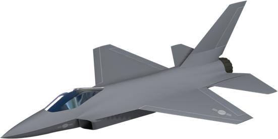
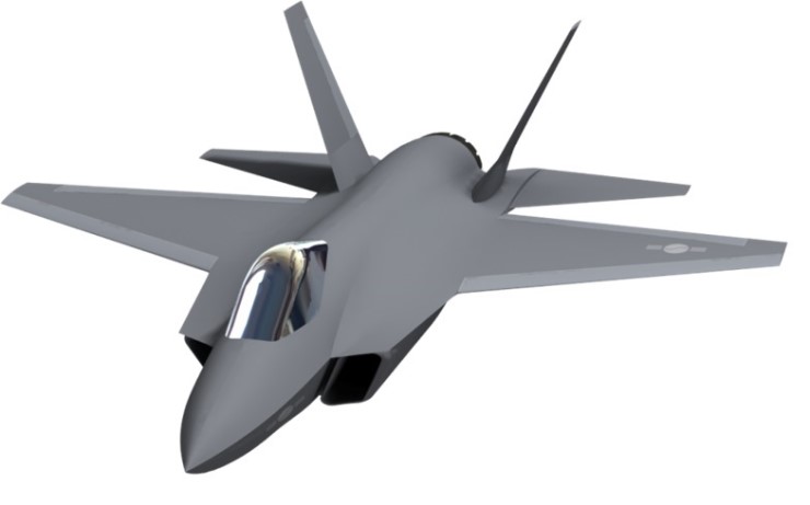
If you want to improve the RCS, take some tips from the Northrop/McDD/BAe JSF.

Increase wing sweep to 45 or more (you want the wing return out of the front quadrant). This probably takes you to a delta (hello Su-75) or lambda wing.
Intake angled at the same angle as the wing leading edge.
Strake should continue rearwards to tail.
Sides and the lower fuselage are very boxy and too close to 90 deg. You really want some more angle on them if possible.
- Joined
- 24 November 2008
- Messages
- 1,549
- Reaction score
- 2,612
If you want to improve the RCS, take some tips from the Northrop/McDD/BAe JSF.
View attachment 672801
Increase wing sweep to 45 or more (you want the wing return out of the front quadrant). This probably takes you to a delta (hello Su-75) or lambda wing.
Intake angled at the same angle as the wing leading edge.
Strake should continue rearwards to tail.
Sides and the lower fuselage are very boxy and too close to 90 deg. You really want some more angle on them if possible.
Thx for your input!
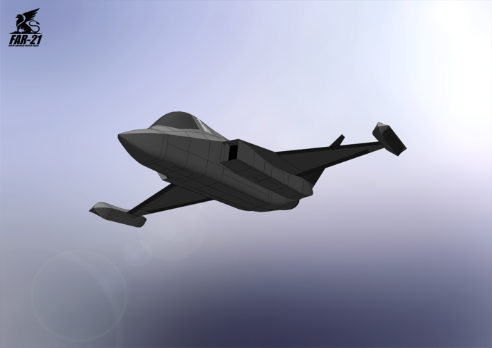
To find the right balance between various (and often conflicting) requirements is not an easy task. You will always find yourself forced to compromise one or the other (e.g. stealth vs. aerodynamic performance).
Having said that, I think the current layout is reasonable and does not feature any fundamental flaws that would disqualify it being a light fifth-generation low-observable fighter. I consider this as the baseline-layout. I may do another variant in the future, but for now I will proceed and see where it gets me. I'm especially keen to see if I will find the required space for the desired minimum amount of fuel.
Last edited:
- Joined
- 24 November 2008
- Messages
- 1,549
- Reaction score
- 2,612
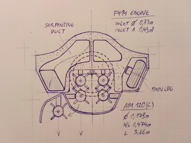
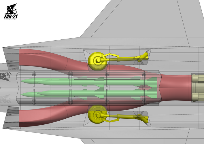
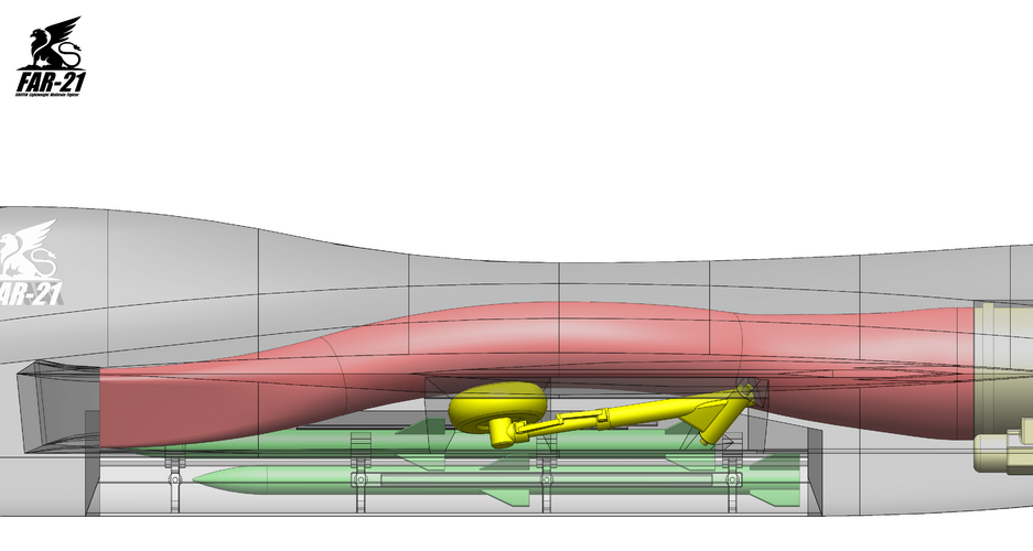
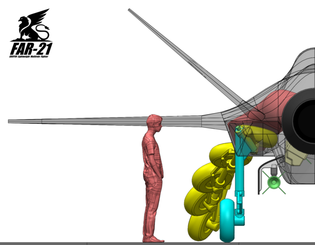
Landing gears... quite challenging and lots of work. Now that I managed to squeeze the wheels behind the air inlet face I'm relieved. And I'm quite happy that the arrangement of the four main items worked out as desired. It all started with a simple sketch
I think ground clearance and distance to the legs is sufficient to allow weapons bay loading with a dedicated trolley.
I think ground clearance and distance to the legs is sufficient to allow weapons bay loading with a dedicated trolley.
Attachments
Last edited:
- Joined
- 29 November 2010
- Messages
- 1,775
- Reaction score
- 3,479
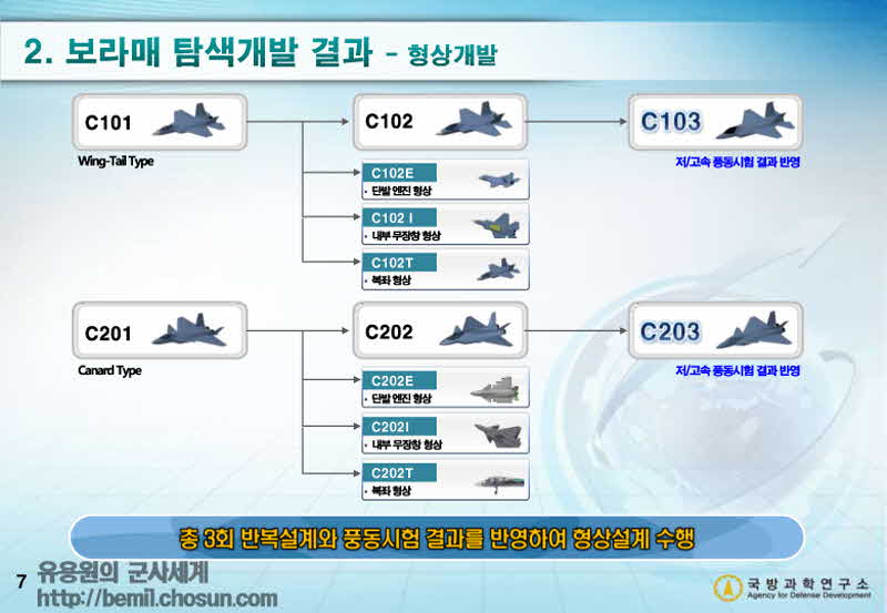
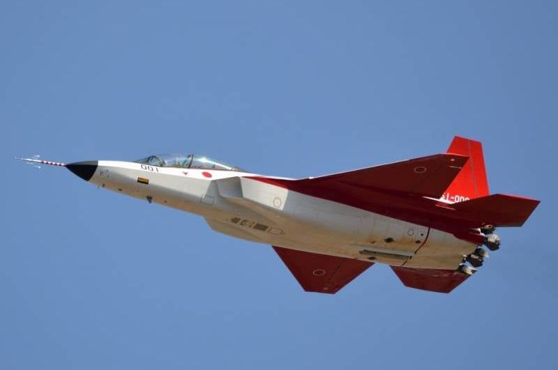
worth noting that before KAI decided on the KF-21s final design..
in the past they considered a single engined lighter fighter in the very early stages
first with twin tails and another with single tails. This was supposed to be more of a straight up F-16 sized replacement
I don't know if this one has space for bays like the other proposals
in the past they considered a single engined lighter fighter in the very early stages
first with twin tails and another with single tails. This was supposed to be more of a straight up F-16 sized replacement
I don't know if this one has space for bays like the other proposals
- Joined
- 24 November 2008
- Messages
- 1,549
- Reaction score
- 2,612
worth noting that before KAI decided on the KF-21s final design..
in the past they considered a single engined lighter fighter in the very early stages
first with twin tails and another with single tails. This was supposed to be more of a straight up F-16 sized replacement
I don't know if this one has space for bays like the other proposals
The influence of the F-16 is unmistakable.
Do you know the dimensions and which powerplant it was supposed to have?
Last edited:
- Joined
- 29 November 2010
- Messages
- 1,775
- Reaction score
- 3,479
i couldn't find any dimensions or specific powerplant.worth noting that before KAI decided on the KF-21s final design..
in the past they considered a single engined lighter fighter in the very early stages
first with twin tails and another with single tails. This was supposed to be more of a straight up F-16 sized replacement
I don't know if this one has space for bays like the other proposals
The influence of the F-16 is unmistakable.
Do you know the dimensions and which powerplant it was supposed to have?
but i did find that the single engined proposal had no internal bay
so the C102E and C202E were single engined (one is canard the other is wing tail).
the I version means it has an internal bay. In this round, the single engined proposal was eliminated and the I model chosen
i guess it would be safe to assume they were intending for a single engined F414 or EJ2000
- Joined
- 24 November 2008
- Messages
- 1,549
- Reaction score
- 2,612
i couldn't find any dimensions or specific powerplant.worth noting that before KAI decided on the KF-21s final design..
in the past they considered a single engined lighter fighter in the very early stages
first with twin tails and another with single tails. This was supposed to be more of a straight up F-16 sized replacement
I don't know if this one has space for bays like the other proposals
The influence of the F-16 is unmistakable.
Do you know the dimensions and which powerplant it was supposed to have?
but i did find that the single engined proposal had no internal bay
so the C102E and C202E were single engined (one is canard the other is wing tail).
the I version means it has an internal bay. In this round, the single engined proposal was eliminated and the I model chosen
i guess it would be safe to assume they were intending for a single engined F414 or EJ2000
Don't you think the single engined proposals would have rather be designed around a PW F100-PW-229 (KF-16)?
Last edited:
- Joined
- 24 November 2008
- Messages
- 1,549
- Reaction score
- 2,612
I found an Flight Global article from 2013 that says:
"...KAI did not state the powerplant for either aircraft, but one source says that it is likely to require similar power to the Pratt & Whitney F100 or General Electric F110, the engines for the F-16 fighter..."
https://www.flightglobal.com/pictures-kai-shows-off-two-designs-for-kfx-fighter/111514.article

- Joined
- 19 July 2016
- Messages
- 4,279
- Reaction score
- 3,462
- Joined
- 21 May 2006
- Messages
- 3,002
- Reaction score
- 2,278
VTOLicious, I've said it once and I'll say it again, very very impressive work!!Landing gears... quite challenging and lots of work. Now that I managed to squeeze the wheels behind the air inlet face I'm relieved. And I'm quite happy that the arrangement of the four main items worked out as desired. It all started with a simple sketch
I think ground clearance and distance to the legs is sufficient to allow weapons bay loading with a dedicated trolley.
Regards
Pioneer
- Joined
- 24 November 2008
- Messages
- 1,549
- Reaction score
- 2,612
Thank you!VTOLicious, I've said it once and I'll say it again, very very impressive work!!Landing gears... quite challenging and lots of work. Now that I managed to squeeze the wheels behind the air inlet face I'm relieved. And I'm quite happy that the arrangement of the four main items worked out as desired. It all started with a simple sketch
I think ground clearance and distance to the legs is sufficient to allow weapons bay loading with a dedicated trolley.
Regards
Pioneer
- Joined
- 24 November 2008
- Messages
- 1,549
- Reaction score
- 2,612
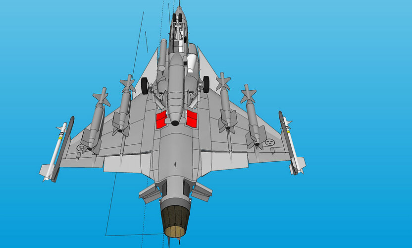
Now it gets interesting, the moment of truth has come!
To model integral fuel tanks I've used a copy of the solid model, cut it into the desired pieces and finally shrinked each one to 85% of the original volume. I've read that's a common method to estimate the volume of integral fuel tanks. As you can see in the pictures, this leaves plenty of space to the outer skin / internal components and accounts for the space required by internal structure as well.

Well, that results in a total fuel tank volume of approximately 3920 liters (3136 kg). Not bad at all!
That's about 1100 liters more than Gripen "L" (2800 l / 2240 kg) and not too far away from Gripen "NG" (4200 l / 3360 kg).
Btw, I've adjusted the front and aft tank's volume so that they are equal to keep the aircraft in balance. Furthermore, I have left plenty of space behind the cockpit to account for avionics, ECS, etc., did not extent the aft tank all the way to the end and didn't fill each tiny space with fuel.

To model integral fuel tanks I've used a copy of the solid model, cut it into the desired pieces and finally shrinked each one to 85% of the original volume. I've read that's a common method to estimate the volume of integral fuel tanks. As you can see in the pictures, this leaves plenty of space to the outer skin / internal components and accounts for the space required by internal structure as well.


Well, that results in a total fuel tank volume of approximately 3920 liters (3136 kg). Not bad at all!
That's about 1100 liters more than Gripen "L" (2800 l / 2240 kg) and not too far away from Gripen "NG" (4200 l / 3360 kg).
Btw, I've adjusted the front and aft tank's volume so that they are equal to keep the aircraft in balance. Furthermore, I have left plenty of space behind the cockpit to account for avionics, ECS, etc., did not extent the aft tank all the way to the end and didn't fill each tiny space with fuel.

- Joined
- 29 November 2010
- Messages
- 1,775
- Reaction score
- 3,479
awesome!
i have a question
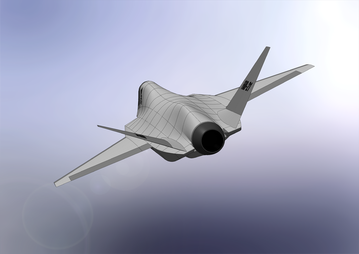
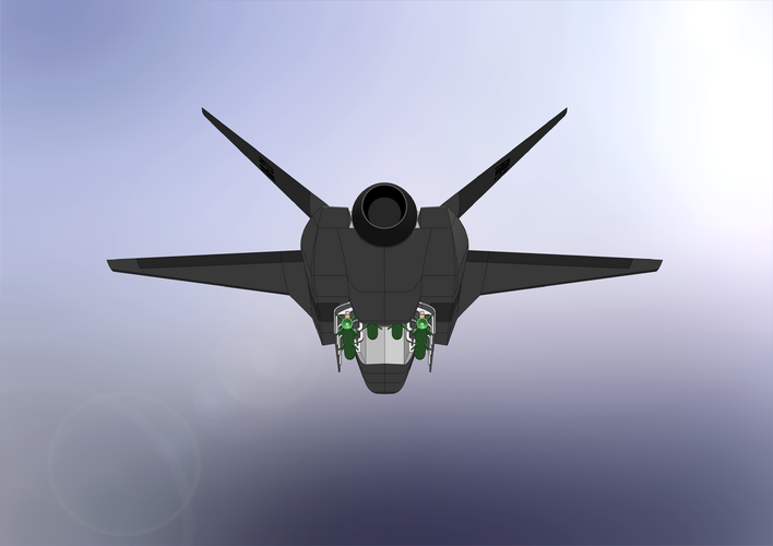
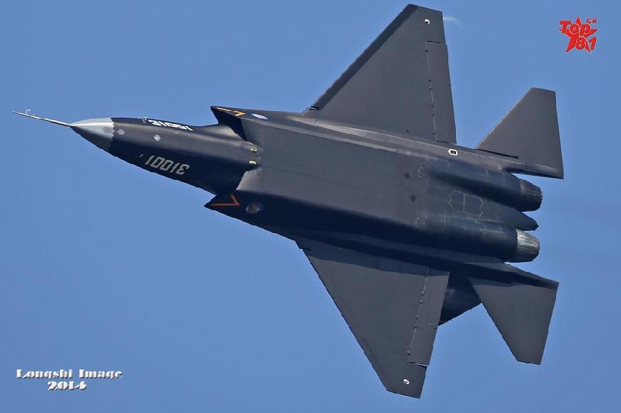
For your design, why did you opt not to have the intakes and bottom fueselage flush with each other?
for example, the F-22 and FC-31, the sides of the intake area and main airframe are flush/flat
the X-2 intakes start off highers like yours,
but eventually merges down to be flush with the bottom (but the internal intakes goes upwards).
yours just stays straight rather than merging with the bottom. Are there any pros and cons to these design aspects?
i have a question
For your design, why did you opt not to have the intakes and bottom fueselage flush with each other?
for example, the F-22 and FC-31, the sides of the intake area and main airframe are flush/flat
the X-2 intakes start off highers like yours,
but eventually merges down to be flush with the bottom (but the internal intakes goes upwards).
yours just stays straight rather than merging with the bottom. Are there any pros and cons to these design aspects?
- Joined
- 24 November 2008
- Messages
- 1,549
- Reaction score
- 2,612
awesome!
i have a question
For your design, why did you opt not to have the intakes and bottom fueselage flush with each other?
for example, the F-22 and FC-31, the sides of the intake area and main airframe are flush/flat
the X-2 intakes start off highers like yours,
but eventually merges down to be flush with the bottom (but the internal intakes goes upwards).
yours just stays straight rather than merging with the bottom. Are there any pros and cons to these design aspects?
The answer is simple: Intake layout was dictated by the IWB-layout I chose. Those doors swing to the sides!

See also:
https://www.secretprojects.co.uk/th...eight-multirole-fighter-lmf.38539/post-506704
https://www.secretprojects.co.uk/th...eight-multirole-fighter-lmf.38539/post-506735
Last edited:
- Joined
- 24 November 2008
- Messages
- 1,549
- Reaction score
- 2,612
Btw, wingtip weapons pods are shown in "Flying Wings and Radical Things" page 256
I've drafted wingtip-pods which can accommodate short range AAM's.
Those pods are in addition to the main bay ( 4x AIM-120) and are intended to be detachable/ interchangeable. The missile would be deployed with a "trapeze launcher", similar to the on used in the F-22's side bays.
Furthermore, those wingtip-pods could also be utilized to house EW- or ISR-equipment, or may be used as additional fuel tanks.
What do you guys think?
Depicted: AIM-132 ASRAAM
Length: 2,9 m
Diameter: 0,166 m
Wingspan: 0,45 m


- Joined
- 24 November 2008
- Messages
- 1,549
- Reaction score
- 2,612
,
Last edited:
The volume of the pod would radically affect the wing tip aerodynamics given that's where your airfoil chord is the shortest.
Either you could investigate adding some extra surface b/w the wing tip and the pod to alter the flow perturbations or use the canoe solution like found on the Felon, pushing your pod inboard where the wing can easier accept such a large volume?
Either you could investigate adding some extra surface b/w the wing tip and the pod to alter the flow perturbations or use the canoe solution like found on the Felon, pushing your pod inboard where the wing can easier accept such a large volume?
- Joined
- 11 March 2012
- Messages
- 3,249
- Reaction score
- 3,179
Can we speculate about a short-range, air-to-air missile with folding fins?
Folding fins could vastly reduce the volume of wing-tip pods.
Square cross-section or hexagonal to allow folded fins to lay flat on the missiles' fuselage.
OTOH your wing-tip pods are a good size to carry extra fuel.
Maybe leave the bad guys guessing as to whether you are carrying extra fuel or extra weapons?????????
- Joined
- 24 November 2008
- Messages
- 1,549
- Reaction score
- 2,612
The volume of the pod would radically affect the wing tip aerodynamics given that's where your airfoil chord is the shortest.
Either you could investigate adding some extra surface b/w the wing tip and the pod to alter the flow perturbations or use the canoe solution like found on the Felon, pushing your pod inboard where the wing can easier accept such a large volume?
Rather large wing tip tanks were used before. Think F-104, F-5,...
However, I do agree that it is necessary to adapt the layout of LE and TE flaps to enable a better connection to the wing's structure.
Last edited:
- Joined
- 24 November 2008
- Messages
- 1,549
- Reaction score
- 2,612
Another option for the internal carriage of SRAAM's would be conformal pods above the air inlets. Similar to the bump on the F-35A, which houses the gatling gun.

Such a conformal pod may provide a solution for an optional gun as well, but I would need to free up some internal space for the ammunition.

Such a conformal pod may provide a solution for an optional gun as well, but I would need to free up some internal space for the ammunition.
Similar threads
-
-
-
-
 Lockheed CL-1200 / X-27 Lancer
- Started by overscan (PaulMM)
- Replies: 84
-
NVLAD by Joint Soviet Fighter
- Started by Joint Soviet Fighter
- Replies: 5