Next steps…
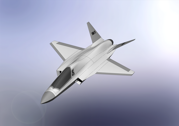
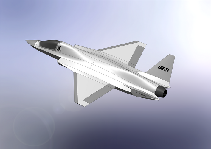
To be able to determine the location of the main landing gear and proceed with the fuselage design I have to decide on a wing and tail layout. Here is what I have so far:
Reference Wing:
Span: 8,4 m (Gripen L)
Reference Area: 27,93 m² (approx. F-16)
Aspect Ratio: 2,53
LE Sweep: 40° (F-16)
TE Angle: 15°
Reference Tail:
Span: 5,1 m
Reference Area: 9,75 m²
Aspect Ratio: 2,67
Ruddervators (V-Tail):
Dihedral Angle: 45°
True Area: 3,99 m² (each) => approx. 29% of wing reference area
Projected Area: 2,82 m² (each) => approx. 20% of wing reference area
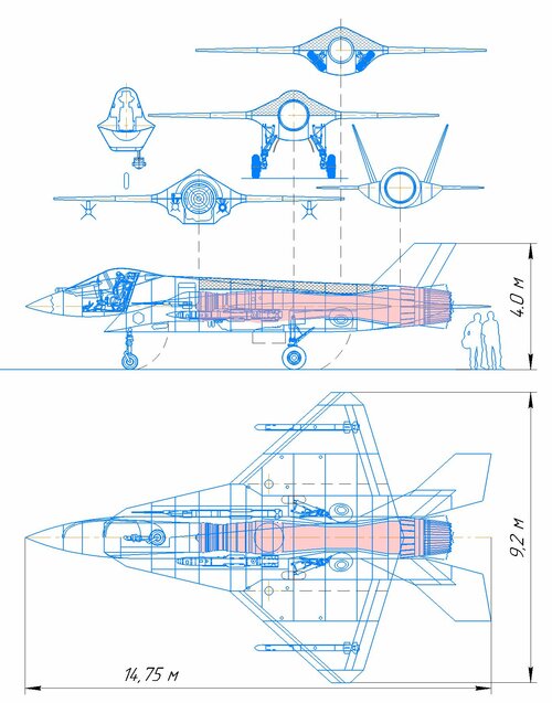
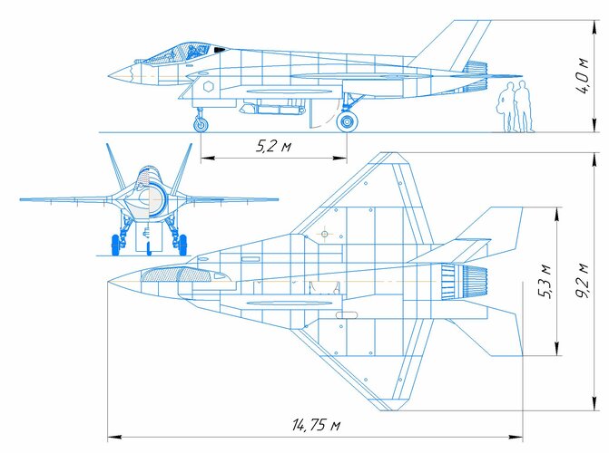
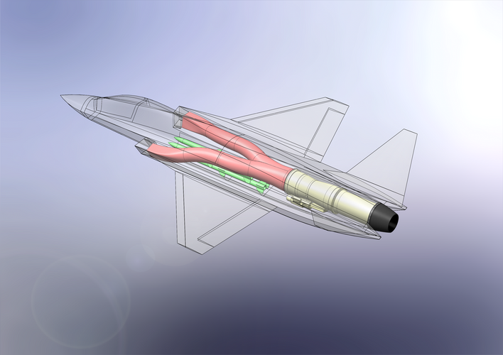
Fuselage Length: 14,5 m
Location of MAC-Wing relative to the Nose: 7,9 m (54,5% of fuselage length)
Distance MAC-Wing to MAC-Tail: 4,705 m
And for the sake of completeness:
Empty Weight: 7600 kg (Gripen NG)
Max. Weight: 16500 kg (Gripen NG)
Wing Loading (Empty): 272 kg/m²
Wing Loading (Max.): 591 kg/m²
Internal Fuel: 2821 l (2268kg @ 0,8kg/l) (Gripen L)
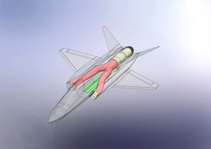
Engine: GE F414 (Gripen NG)
Thrust without AB: 63,47 kN
Thrust with AB: 97,99 kN
All of that is preliminary parameters. Comments welcome!
View attachment 671290

")