Dassault Rafale Avionics

E

Exit

Guest
Dassault Rafale

Some pics of avionics interface from Global Punch video:

Rafale_avionics1.jpg

Rafale_avionics2.jpg

Rafale_avionics3.jpg

Rafale_avionics4.jpg

Rafale_avionics5.jpg

Rafale_avionics6.jpg

Rafale_avionics7.jpg

Rafale_avionics8.jpg
 
http://www.armees.com/Tir-MICA-depuis-un-Rafale-F2-quand-le-chasseur-devient-la-cible,22155.html

Sorry this is in French.

On 11 of June the french CEAM (military air experimentation centre) successfully tested a new kind of shooting.
A Rafale F2 shot a target behind him (and killed it) thanks to data transmitted from another Rafale with Link 16.
The missile used was a Mica EM (active radar seeker). This missile has thrust vector control and can be fitted indeferently with IIR or active radar seeker, and can be shot BVR (30 NM, maybe more, depending on launch conditions) or in close combat with a helmet cueing system.

The Rafale has also recently demonstrated that it has multitarget capability in air to ground role, with AASM. It can shoot at 6 different targets in one pass. One of the firing was nearly 90° of aircraft flight path.
The AASM is a kit with GPS guidance and rocket engine, fitted on Mk 82 bomb, giving it around 15 km range on low level firing and more than 50 km at high altitude.
 
The Rafale features a fully integrated digital avionics suite with a modulare core architecture:

MDPU:
The modulare data processing unit (MDPU) form the heart of the Rafale's avionics. It's a modulare mission computer cmprising 18 processor modules. The MDPU is said to be 50 times faster than the Mirage 2000-5s mission computer and hosts the software for most of the aircraft's systems and avionics.

Networking:
The avionics integration is assured by linked the various systems to each other via at least 4 digital MIL STD 1553B databusses and at least 1 optical STANAG 3910 datbus. Communication between the aircraft's onboard systems and its weapons is enabled by 2 digital MIL STD 1760 databusses.

Recording:
The Rafale's recording systems include a Thales ESPAS digital solit state flight data recorder and a OTA 1320 CCD TV camera plus recorder for HuD video footage. The recording systems record maintainance data as well.

IUHMS:
The integrated usuage and health monitoring system (IUHMS) features fully integrated and automated built in test equipment (BITE) along with sensors and digital recorders for airframe structure and engine components life monitoring.

Navigation:
The Rafale's navigation suite includes two Sagem RL-90 LINS platforms with embedded NSS-100 GPS receivers. The LINS allows flight plans with up to 600 waypoints being programmed and stored.
Addiotnal navigation equippment includes the NC-12E TACAN radio navigation system, the TLS-2020 multimode receiver which includes VOR and ILS/MLS functions, a digital map generator (DMG), a digital terrain reference navigation system (TRN) and the digital AHV 2930 radar altitmeter which is optimised for discretion and high performance at very low altitudes. The radar altimeter works at altitudes up to 3200 m.

Communication:
The communication equipment comprises EAS TRA 2020 V-/UHF radios for civil communication and secured TRA 6032 V-/UHF radios for tactical military communication, compatible with HQ I & II and SATURN standards. The aircraft additionally features the MIDS-LVT/LINK16 bi-directional data link terminal for secured and jamming resistent near real time communication and data exchange.

Autopilot:
The known Autopilot modes include:
- Flight path tracking
- Altitude hold modes
- AoA hold mode
- Auomatic terrain following
- Auto throttle

Self Defence:
The Rafale's SPECTRA (Système de Protection et d'Evitement des Conduites de Tir du Rafale – Self Protection Equipment Countering Threats of Rafale Aircraft) is one of the most advanced EW suites ever created for a combat aircraft. Being of a modulare design, SPECTRA is controlled by the GIC computer (Gestion de l'Interface et Compatibilité) comprising 3 processors.
The SPECTRA components include:
- 3 digital RWR antennas with each 120° azimuth coverage and a frequency coverage of 2 - 40 GHz mounted on the airlift intakes and at the rear of the SPECTRA fin tip pod. Functions/characteristics include:
- detection localisation, identification and priorisation of radar emitters at distances up to 200 km+
- Bearing accuracy below 1° in azimuth using interferometry
- Weapon cueing against ground based emitters
- ELINT/SIGINT

- Active ECM system with DRFM and AESA antennas in the canard roots and in the tail pod at the base of the fin, with offensive, defensive and stealthy jamming modes. Pencil thin jamming beams are directed towards threat emitters

- DDM (Détecteur infrarouge de Départ de Missiles) missile approach warning system based on dual-band midwave IR sensors which are located on each side of the SPECTRA fin tip pod, providing 360° atimuth coverage

- 3 DAL (Detecteur d’Alerte Laser) laser warning receivers with sensors on the fuselage sides and the rear of the SPECTRA fin tip pod

- 4 vertical firing flare/decoy dispensers on the top of the fuselage near the wing trailing edges and 2 chaff dispensers on the rear fuselage sides behind the wings

Note:
The RWR and ECM systems are integrated as the DBEM (Détection et Brouillage Electromagnétique) sub-system.

Radar:
Thales RBE2 (Radar a Balayage Electronique – deux plans) is a modulare designed monopulse-doppler X-band multimode fire control radar system. It features 4 LRI including:
- ~60 cm PESA antenna
- 4 channel receiver
- transmitter
- programmable signal processor with at least 2 bln flow point operations/second

The RBE2 provides a +/- 60° azimuth and elevation coverage and includes the SB-25A MkXII compatible IFF interrogator/transponder with Mode-S capability. The IFF system uses phased array antennas.

Air to Air modes/functions include:
- Long range search
- Multi target track and engagement
- Air combat modes
- NCTR
- RAM
- Look down/shoot down

In AA mode the RBE2 offers a tracking range beyond 100 km against a 3 sqm target with detection ranges up to 130-140 km. The radar can track and prioritise up to 40 targets simultaneously, engage up to 8 of them and provides McG for up to 4 missiles. It includes LPI characteristics and as capable of track here while scan there.

Air to Ground modes includes:
- DBS mapping
- SAR mapping
- FTT
- SEA surface search and TWS
- GMTI/T
- TA
- AG ranging

Terrain following and avoidance modes can be combined to generate 3-D radar maps, which enable automatic terrain following flights via radar. AA tracking and AG mapping can be interleaved due the radars agile beam sweeping capabilities.

Electro optical systems:
The OSF (Optronique Secteur Frontal) comprises two modules on the aircraft's nose. The right one features an imaging dual-band IRST/FLIR sensor (3 - 6 and 8 - 12 microns) and the left one, aka CIU (Combat Identification Unit) features a 3-D CCD TV camera and a laser range finder.
The IRST provides a +/- 90° azimuth coverage and is capable to detect and track multiple aerial targets simultaneously. The sensor offers a max. detection range of 130 km in best conditions and can act as FLIR providing target images up to ~40 km and nav-images presented on the HuD.
The TV camera offers a max FOV of 60° and a range of ~50 km for single target track and identification. The LRF is effective up to ranges of 33 km.

Sensor fusion:
All the Rafale's onboard and offboard sensor data are fused, creating track files which contain correlated data from all the aircraft's sensors and which are presented on the large Head Level Display.
 
New, noteworthy avionics capabilities coming into Standard F4, especially the Standard F4-2, would include :

CONTACT SDR radar, basically a French equivalent of JTRS radios.
ESSOR framework based data link waveform, (heard it's UHF) would be installed as an OFP in CONTACT.
FO3D intra-flight data link system. (Heard there's a future capability upgrade planned for it to incorporate Ku band directional communication)
TRAGEDAC intra-flight data fusion, fusing data from SPECTRA, OSF and radar of each Rafale aircraft with the other.
SCORPION HMD.

Possible amplitude-phase difference directional detection capabilities for the RWR? Those Gripen Es have them so it wouldn't come as a surprise if the new Standard F4-2 Rafales are going to have them since the SPECTRA suite is also receiving upgrades.

I've heard GaN based MMIC on RBE2 TRM are planned for F5. That probably means only radar back-end and software upgrades for the F4-2.
 
My question now would be if the French have any plans of integrating RIFAN 2's waveform into CONTACT radio. Since RIFAN 2 is going to be installed on more than 60 aircraft, the OFP is already there. It's also UHF and would be installed on maritime helicopters, which means that the size of the radio ain't going to be as huge as CETPS systems for the CEC.

This especially makes sense considering the fact that Marine Nationale is developing VCN based on RIFAN 2. Just like how USN is demonstrating NIFC-CA FTS with CMN-4 based waveforms like Link-16 ET or TTNT, MN could possibly do the same by connecting the ships with carrier based Rafale M via RIFAN 2.
 
https://adsabs.harvard.edu/full/1996ESASP.375..111N a paper on the Rafale’s mission computer. It seems like the F1 (which used a different interm off the self system) is totally different in terms of avionics. The computer seems to be what makes the Rafale the “Omnirole” we all know.


I’ve been interested in the RBE2 is basically alone as the only western PESA and one of the earliest phased arrays. Unfortunately it doesn’t seem to have gotten its full potential till the F2 and F3 standard which came about when AESA started becoming mainstream but still interesting.

The system is based on “Radant” technology developed by the company of the same name.


This function can be performed via the reading of a file, and therefore without electromagnetic emission, which promotes the discretion of the aircraft. 2 secure maps of about 300,000 km2 then allow low-altitude navigation by cutting the terrain for 10 km forward at just 300 ft ground (or even 100ft).
To this, the radar can associate a 3D mapping to circulate outside the stored file, if necessary.
Depending on the desired level of discretion, the pilot can choose 3 flight options: flexible, medium or hard. The "hard" level makes it possible to reach speeds well above the Mirage 2000N/D, as well as higher load factors...
9 navigation corridors are managed in field tracking mode.
With the arrival of the RBE2 AESA, the PESA antenna is not forgotten, since a modernization of the SdT capacity is underway and will aim to increase "low flight at very high speeds" capacity.
SAR image from RBE2 AESA
  • DBS mode: Doppler Beam Sharpenning.
This function allows you to approach a lens at low altitude, unmask very briefly to map it, and then work on the image thus memorized.
  • PDS mode: Plan of symmetry.
Consists of a vertical search in the aircraft axis in order to pursue a hostile u that would try to escape by maneuvering aggressively.
  • IDF mode: identification.
special guiding law used to observe, identify and possibly force an opponent to land.
  • Memory mode.
Intended to compensate for the "gaps" of the Doppler effect when an aircraft positions itself perpendicular to its interceptor. The system then develops a trajectory forecast based on the last known elements.

Sources: Air Fan June 2001 and June 2005 - June 2007


The prototype was first flight tested in 1992 and fitted to a prototype Rafale (B02) in 1993. The first production version was delivered in 1997 and installed on a Dassault Mystere 20 and Mirage 2000 before production Rafales. F2 standard added air to ground and limited terrain following/mapping, all features added for F3. Said to combine best features of RDM, RDY, RDI, Antilope radars with comparable quality to RDY (antidotally the RDY has a slight range advantage) as well as adding interleaving of different modes.
 
The F1 was truly a castrated Rafale. But had the Aéronavale waited for a naval Rafale F2, the Crusaders would have had to last until 2004 ! As if 1999 or 2001 wasn't already catastrophic enough...
And so the F1 was allowed to happen for minimal IOC by May 2001. Note that the Armée de l'Air never wanted it and never got it. They had Mirage 2000-5 that (somewhat ironically !) were used to transition the last Crusader pilots from the 1950's to the 2000's - must have been one hell of a shock !!!
 
Nvm.. found it..it operates at both Mid and Long wave.
I think I missed what you where looking for.
Oh i was asking about the operational wavelength of the OSF-IR. Turns out i missed the part of Scorpion's post where he mentioned the characteristics of the OSF-IR.

It is both Mid and Longwave system.
 
Radar choice
In the field of radar, this resulted in the decision to reopen competition between Thomson-CSF and ESD, whereas previously an orientation favorable to Thomson-CSF had been taken and, moreover, Thomson had a definite lead within the framework of preparatory studies, in particular with RACAAS227.
As Francois Flori points out in his testimony on this period:
“One of the major points for the definition of the future radar was the front assembly, transmitter and antenna. Indeed, the radar was required to have all the air-to-air functions, ground vision with precise mapping, tracking and avoidance of terrain at low altitude, close combat modes... Grouping together in a single radar functions hitherto allocated to specialized on-board radars was a challenge, especially since a certain simultaneity of functions was also required, such as, for example, air-to-air detection of hostiles for self-protection during low-altitude penetration phases. The beam agility of a phased array antenna was essential to meet these demands, and the choice of technical solution in this area was
crucial. »
The two companies Thomson-CSF and ESD were therefore called upon to respond to a consultation launched by the STTE at the end of 1986:
- Thomson-CSF offered the RDX project in a Radant "two-plane" electronically scanned version with a fixed antenna, while a less efficient single-plane electronically scanned variant was also presented.
- ESD had considered the Radant process as too risky in terms of deadlines and, in any case, had no longer had access to it since the takeover of the Radant company by Thomson. ESD proposed the Antilope 60 project with a fixed "two-plane" electronically scanned front assembly using passive ferrite phase shifters. Furthermore, ESD strongly contested the adaptation of “one shot” scanning to the need expressed.
The new General Delegate for Armaments, Jacques Chevallier, wondered about the feasibility of the proposed solutions. He asked his American counterparts, who agreed, to do an audit on the subject. This took place with the participation of representatives of the STTE.
The result did not reveal any impossibilities in principle. However, the American technicians had to be convinced of the validity of the Radant process, which they did not know. The STTE was able, fortunately, to provide convincing results in April 1987, in line with forecasts, on the diagrams of the “two-plane” Radant antenna.
But the problem of choice still remained. After various proposals from industrialists and a last round of consultation in 1988, the DGA chose a definition of radar, based on the Thomson-CSF proposal, with the Radant front assembly "two planes", but taking up certain elements of the proposal from 'ESD, especially the transmitter.
As stated above, the Minister, in his decision of November 22, 1988, accepted the proposal to create a legal structure whose leader would be Thomson-CSF and which would be responsible for building the radar on the basis of a distribution: 2/3 Thomson, 1/3 ESD.
In application of the guidelines set, the two industrialists formed the GIE Radar ACT/ACM Rafale. The proposal resulting from the agreement is the REG, very close to the Thomson-CSF RDX, with the "two-plane" Radant assembly and for which the transmitter, the antenna pointer, the structure and elements of the receiver pilot are made by Dassault Electronique.
An order letter will be sent to the GIE in April 1989. The REG228 became the RBE2 (for two-plane electronic scanning radar).
We know that subsequently the two companies were united within the Thalès group.
The definition of a new combat aircraft presupposed the development of a new high-performance radar. The first studies were launched in the early 1980s by the DGA and the DCAé for the definition of a radar integrating new component and material technologies by taking up many of the achievements of the RDY radar. These studies envisaged a Thomson CSF RDX radar, designated RACAAS, which made its first flight at the end of 1986 mounted on a CEV Mystery XX. For its part, the ESD was working on a development of the Antilope V radar, the Antilope 50, tested on a CEV Mystery )0( at the beginning of 1988. Thomson CSF and ESD were in competition for the Rafale radar, but neither in 1986 nor in 1988 did the DGA manage to decide between the two projects.On September 1, 1988, the Ministry of Defense asked the two companies to join their efforts, justifying the creation of a DIE, in order to achieve a development - financially reasonable technical development. The EIG Radar ACT/ACM had as leader Thomson CSF involved in two thirds of the project, ESD supporting the remaining third. This EIG undertook the development of the RBG radar project, leading to applications allowing versatility of functions: • [air-to-air interception and combat by firing the new MICA missile by automatically detecting and
 

Attachments

  • 83BD664E-4B4F-49EA-8CAE-6BE39055A6F6.png
    83BD664E-4B4F-49EA-8CAE-6BE39055A6F6.png
    315.2 KB · Views: 82
Last edited:
Some Rafale has spherical sensor at the tail, some has the boxy facet one.
So which one is newer?
Capture.PNG
 
The sensors in question are infrared missile warning sensors and are part of the Thales SPECTRA (Système de Protection et d'Évitement des Conduites de Tir du Rafale) system. The spherical one is the newer system.
 

I was reading this and something caught my eye

It says it scans at 110 degrees a second? I thought it would be faster. I think apg-63 is 70 degrees a second?
 
This is a 2000's flight simulator. It was shutdown (IP not security concern) but the lead worked on the Rafale's Avionics. It explains how a lot of the cockpit systems work (in French)
 

Attachments

  • Manuel Rafale F2.pdf
    2 MB · Views: 163
It says it scans at 110 degrees a second? I thought it would be faster. I think apg-63 is 70 degrees a second?

What mode tho ? I would expect it's just one among several "selectable" scan rates. for Phased arrays the scan rate can be precisely controlled by the computer according to the mode requirement.

---------

One question. Does French have other kind of datalink than NATO standard Link-16 ?
 
It seems technical issues caused the existence of the Rafale F1

From AWST

Air-Ground Work Lags​

JUNE 121995
AIR-GROUND WORK LAGS
PARIS AIR SHOW '95
BRETIGNY FLIGHT TEST CENTER, FRANCE
The air-to-air capabilities of the Thom-son-CSF phased array radar for the Rafale continue to mature, but development of its air-to-ground modes has been delayed significantly.
The Thomson-CSF RBE2 radar eventually is to perform complex air-to-air and air-to-ground functions simultaneously.
But development of individual ground capabilities has been difficult, as has software development for combined air-to-air and air-to-ground operations, according to Yves Zundel, deputy Rafale technical manager for DGA, the French armaments agency. The DGA funds and oversees the program contractors. Dassault Electronique is teamed with Thomson for software and other radar function development in the RBE2 program. Much of the radar's testing on a DGA/Dassault Falcon 20 is based here.
The first 16 French navy versions of the aircraft will be equipped with only air-toair radar modes.
AN ADDITIONAL ai r-to-ground capability had initially been planned for a second block of navy aircraft, Zundel said, but this has been delayed.
In addition to the technical challenges, overall French defense budget cutbacks have also been a significant factor in the radar's development.
"The first challenge has been to develop the specific modes, such as air-toground [attack] and terrain following," Zundel said. But due to early problems, development of the terrain-following modes has been largely deferred. Work on the air-toground features will be deferred for 1215 months, he said.
Radio altimeter data is being used quite successfully, however, to test the aircraft in a sea-skimming mode.
"The second challenge is to integrate the radar's software capabilities so they can operate simultaneously," Zundel said.
"For example, you should be in terrainfollowing mode and simultaneously have the radar in a time-sharing mode providing air-to-air surveillance," he said. But this software capability will be delayed until air force versions of the aircraft are produced about 1999-2000, he said.
The program's No. 6 development radar is currently in the MOI Rafale aircraft and is to be used for the Mica missile attack on a drone by this week. Extensive radar testing on the Falcon and other flying testbeds has been planned all along, other DGA officials here said.
 
It says it scans at 110 degrees a second? I thought it would be faster. I think apg-63 is 70 degrees a second?

What mode tho ? I would expect it's just one among several "selectable" scan rates. for Phased arrays the scan rate can be precisely controlled by the computer according to the mode requirement.

---------

One question. Does French have other kind of datalink than NATO standard Link-16 ?
According to Razbam who worked with the French Air Force the mirage 2000 had a kind of rudimentary datalink


Test of “RADANT” lense similar to RBE2


France Nears Decision on Supplier for Next-generation Fighter’s Radar​

SEPTEMBER 51988
France Nears Decision on Supplier For Next-Generation Fighter’s Radar
FARNBOROUGH AIR SHOW
PARIS
The French defense ministry is expected to decide shortly whether to select Electronique Serge Dassault (ESD) or Thomson-CSF to develop the multifunction radar for France’s next-generation aircraft combat tactical (ACT), a production version of the Dassault-Breguet Rafale.
Both companies proposed use of an electronic-scan, phased-array antenna, but each proposes to use different scan techniques.
The rivalry between the two companies in the military airborne radar field is as sharp and long-lived as that in the U. S. between Hughes Aircraft and Westinghouse, but with one chief difference. Hughes and Westinghouse compete under “winner-take-all” rules, while in France the loser typically becomes a subcontractor to the winner.
This practice has enabled France to enjoy the economic and technological benefits of competition while allowing ESD and Thomson-CSF to survive and prosper. It consequently has provided France’s aircraft, helicopter and missile manufacturers with a broad spectrum of radars.
DOMINANT IN MARKETS
In 1987, ESD produced nearly $150 million in military aircraft radars, almost one-quarter of the company’s total sales. Thomson-CSF’s 1987 sales of airborne military radars were more than double ESD’s—roughly $350 million. This represents about half the total output of the Radar Counter-Measures (RCM) Div. and one-quarter of the sales of its parent Aerospace Group.
The scope of Thomson-CSF’s radar business has expanded with its acquisition of Omera-Segid’s line of helicopter radars, as well as airborne and groundbased battlefield surveillance radars developed by LCT, formerly owned by ITT Corp.
ESD is France’s dominant supplier of microwave missile seekers. This includes active types for the Aerospatiale Exocet antiship weapon, semi-active for the Matra Super 530D/F air-to-air missiles and passive devices for the new Matra Star antiradar missile.
ESD also was selected to develop the active radar seeker for one version of the new Mica air-to-air missile—the French counterpart of the USAF/Navy AMRAAM (AIM-120A). (The other version will use an infrared seeker, supplied by France’s SAT.)
Last year, ESD delivered more than
$130 million in microwave missile seekers, more than one-fifth of the company’s total sales, according to Jean Climaud, ESD’s director general for administration.
For Thomson-CSF, microwave missile seeker sales last year totaled about $70 million, corresponding to about 10% of the output of the RCM Div. Current pro-
duction includes active seekers for the Matra Otomat and Messerschmitt-Boelkow-Blohm Kormoran-1 antiship missile.
But it has developed a new, all solidstate version for the new MBB Kormoran2 that is more resistant to enemy countermeasures and need not radiate continuously during its terminal phase. First
production is expected in the early 1990s.
Thomson-CSF is focusing its efforts on developing millimeter-wave active-radar seekers for new antitank weapons, including one called Adam, a field in which ESD also is active.
Nearly 20% of ESD’s business and about 40% of the sales of ThomsonCSF’s RCM Div. are in electronic warfare.
Thomson-CSF’s RDI radar was selected for the air defense version of the Mirage 2000, with ESD participating as a subcontractor. ESD’s Antelope-5 mapping/terrain-following radar was picked for the nuclear-strike version—the Mirage 2000N—with Thomson-CSF serving as a subcontractor.
SUPER ETENDARD RADAR
ESD recently was selected to develop the Anemone, a very compact, pulse-Doppler radar for the French navy Super Etendard, to replace the Thomson-CSF Agard radar. The new radar is scheduled for production in the early 1990s, Climaud said.
Thomson-CSF is flight testing two prototypes of its RDY airborne radar, developed with company funds for the export market in the early 1990s on the Mirage 2000-5.
The RDY is the first airborne radar developed in Europe to use a programmable signal processor (PSP), according to Pierre Baratault, technical manager of the RCM Div. The PSP, which uses multiple microprocessors, can operate at a speed of 1 billion floating-point operations/sec. (1 gigaflop), according to Baratault, and occupies less than one-sixth of a cubic foot.
This high-speed processor is one of several RDY radar features that also would be included in the RDX that ThomsonCSF has proposed for the ACT.
Both the RDX and RDY pulse-Doppler radars offer three different pulse repetition frequencies. The system automatically selects the optimum PRF for the mission conditions, depending on relative speeds of host and target aircraft, target range, and clutter or jamming, Baratault said.
For example, low PRF is used against “look-up” airborne targets, for groundmapping, terrain-following and avoidance and against surface targets. Medium PRF is employed against “look-down”-type airborne targets at medium range. High PRF is used against targets at long range.
The most significant difference between the RDY and proposed RDX radars is that the former uses a traditional, mechanically scanned slotted planar antenna, while the system proposed for ACT would use a phased-array antenna.
Neither company chose to propose an active-aperture phased array antenna for ACT, primarily because of cost and the aircraft timetable, which calls for production in the mid-1990s. But both are active-
ly developing the microwave integrated circuit technology that is needed for such arrays.
For example, ESD has developed an active element (receiver/transmitter/ phase-shifter) that has a 10-w. output at the X-band, a 10% bandwidth and an efficiency of nearly 20%, according to Jean-Etienne Connet, the company’s technical director.
ESD is under contract to develop an airborne active-aperture conformal antenna for satellite communications in the 7/8-GHz. band.
“But at this stage of the technology, active apertures for airborne radar face a number of economic and technical hurdles,” Connet said.
SYSTEM’S RESTRICTIONS
Connet acknowledged that the team of Westinghouse and Texas Instruments is developing an active-aperture array radar for both the Lockheed and Northrop advanced technology fighter (ATF) aircraft. But he noted that the ACT/Rafale nose radar antenna diameter is limited to 66 cm.—significantly smaller than the ATF.
“With an active-aperture antenna, when you reduce size you reduce both power and gain. For ACT, each element would need to radiate 10-15 watts, and that is beyond current, cost-effective technology,” Connet said.
Under U. S. Air Force sponsorship, Texas Instruments has pioneered in activeaperture elements for use in airborne radar. Texas Instruments has reached a technology-exchange agreement with Thomson-CSF, but so far the pact has not been approved by the U. S. government.
A prototype of the radar that ESD has proposed for the new ACT, referred to as the Antelope 50/60, has been undergoing flight test at the French government’s Bretigny test center since 1987, Climaud said.
An important feature of ESD’s proposed phased-array antenna is the rapid pointing agility of its beam. Connet said switching time “is only a few microseconds, compared with a few milliseconds for previous designs, without increased power consumption.”
The radar proposed by Thomson-CSF for the ACT will use a new phased-array beam-steering technique, called Radant, for which the company holds a patent.
Radant employs two dielectric lenses— one to focus and steer the beam from a klystron-powered feed in azimuth and a second to steer it vertically. Beam focusing and steering is accomplished by changing the bias voltages on individual diodes embedded in the dielectric lenses.
Thomson-CSF’s Baratault said the Radant technique is less costly than using individual, ferrite phase shifters for each radiating element, and provides a beam with minimal sidelobes.
The growing role envisioned for heli-
copters in European military operations has prompted Thomson-CSF to expand the line of helicopter radars it acquired from Omera-Segid. For instance, Thomson-CSF has developed and is flight testing a millimeter-wave (94-GHz.) radar, called Romeo, for helicopter obstacle detection/terrain warning under all-
weather and night conditions. Romeo uses a color display to show power lines and terrain near the helicopter’s flight level.
Thomson-CSF also is marketing the Orchidee helicopter borne battlefield surveillance radar. The radar was developed by LCT, which was acquired by ThomsonCSF in 1986. Orchidee is undergoing
flight tests on board an Aerospatiale Puma.
The frequency-modulated, continuouswave radar, which weighs less than 50 lb. (22.6 kg.), is designed to scan 120 deg. in azimuth and 30 deg. in elevation. It was developed using company and defense ministry funds.
HELICOPTER APPLICATIONS
An ESD-developed, mast-mounted, Xband helicopter radar, called DAV, is to be flight tested later this year. It is intended to detect low-flying enemy helicopters at ranges of up to nearly 5 mi.
Developed under French government sponsorship, the DAV is a candidate for use on the new French/German multimission helicopter, and the planned NATO NH-90 helicopter.
For the NH-90, ESD and ThomsonCSF will be competing as members of two European industrial teams. ESD is teamed with Italy’s Selenia, West Germany’s Siemens and Hollandse Signaalapparaten of the Netherlands. Thomson-CSF will be teamed with Italy’s FIAR, West Germany’s AEG and the Netherlands Radar Laboratory.
The defense ministry is sponsoring the development of a standard family of French Military Computers (CMF), for aicraft, ships and surface use. ESD was selected as the prime contractor for the
airborne computer (CMF-Air) in collaboration with Sagem. The CMF-Air initially will be used in ACT.
Meanwhile, ESD has developed a Model 2084XR for use on new-generation Mirage 2000 aircraft. The 2084XR can operate at a speed of more than 1 million operations/sec. It uses a 32-bit Motorola
68020 and two 68881 coprocessors, and includes 768K of random access memory.
To minimize the size and weight of the 2084XR computer, ESD employs a very large hybrid microcircuit, using what it calls “macro-hybrid” technology. As many as 200 uncased chips are mounted on both sides of a 16-layer ceramic substrate measuring 7.6 X 12.5 in. and interconnected using bonded gold wires.
ESD has been fabricating such very large hybrids for three years.
ESD will apply its macro-hybrid technology to the new VHSIC avionics microprocessor (VAMP) that Westinghouse is developing for USAF’s Avionics Laboratory under the terms of an agreement between the two companies that is expected to be approved shortly by the Pentagon and French defense ministry.
'PI BUS’ STANDARD
Under the technology-exchange agreement, ESD will fabricate Westinghouse’s design of a 16-bit Mil-Std-1750-type microprocessor using uncased VHSIC chips and macro-hybrid technology.
This will allow the processor and 256K of memory to be packaged on a single, two-sided SEM-E module—which measures about 6x6 in.—instead of requiring two such modules.
The module will include provisions for the new U. S. Defense Dept, standard “Pi bus,” which is to be used to interconnect plug-in modules on “motherboards” for future military systems.
ESD also will supply a modified version of the 32-bit PMF processor it has developed for the French government, including a Pi bus provision. This will enable the U. S. Air Force to evaluate the new French 32-bit processor while serving to introduce the Pi bus architecture in West Europe. □

Done Reading
AWST September 5th 1988
 
Article on

Spectra​


Attachments

  • 78EA874D-14D8-4FDF-8282-16ACA636EAFC.jpeg
    78EA874D-14D8-4FDF-8282-16ACA636EAFC.jpeg
    4.7 MB · Views: 43
  • 358D86AD-99D3-4365-A7F6-10024D2DA323.jpeg
    358D86AD-99D3-4365-A7F6-10024D2DA323.jpeg
    4.7 MB · Views: 51
  • CAD26290-629B-42F5-9F05-F151CC09F0E5.jpeg
    CAD26290-629B-42F5-9F05-F151CC09F0E5.jpeg
    5.2 MB · Views: 39
  • 67239A6F-E03F-4C0B-A68C-2A4217B3E585.jpeg
    67239A6F-E03F-4C0B-A68C-2A4217B3E585.jpeg
    5 MB · Views: 35
  • 7E17F511-3520-40C1-B963-2BDAA116FB66.jpeg
    7E17F511-3520-40C1-B963-2BDAA116FB66.jpeg
    5.1 MB · Views: 43
  • 5D957393-15EE-434E-B102-32603776FA30.jpeg
    5D957393-15EE-434E-B102-32603776FA30.jpeg
    5.2 MB · Views: 41
  • 372FD879-FE16-43AE-B217-B97A9A7BC273.jpeg
    372FD879-FE16-43AE-B217-B97A9A7BC273.jpeg
    5.4 MB · Views: 40
  • DFFCE5E0-3746-44A5-9187-9F89DE5497AF.jpeg
    DFFCE5E0-3746-44A5-9187-9F89DE5497AF.jpeg
    4.8 MB · Views: 34
  • DEA60104-1C4A-48B1-8FCD-DCE35292154D.jpeg
    DEA60104-1C4A-48B1-8FCD-DCE35292154D.jpeg
    5.3 MB · Views: 31
  • B13838EB-0D35-4C4B-8E17-C8055072752E.jpeg
    B13838EB-0D35-4C4B-8E17-C8055072752E.jpeg
    5.2 MB · Views: 30
  • 2AA04DC7-3ADC-4EB7-8C4C-A6A912EBF156.jpeg
    2AA04DC7-3ADC-4EB7-8C4C-A6A912EBF156.jpeg
    2.7 MB · Views: 40

Attachments

  • 178.pdf
    475.9 KB · Views: 28
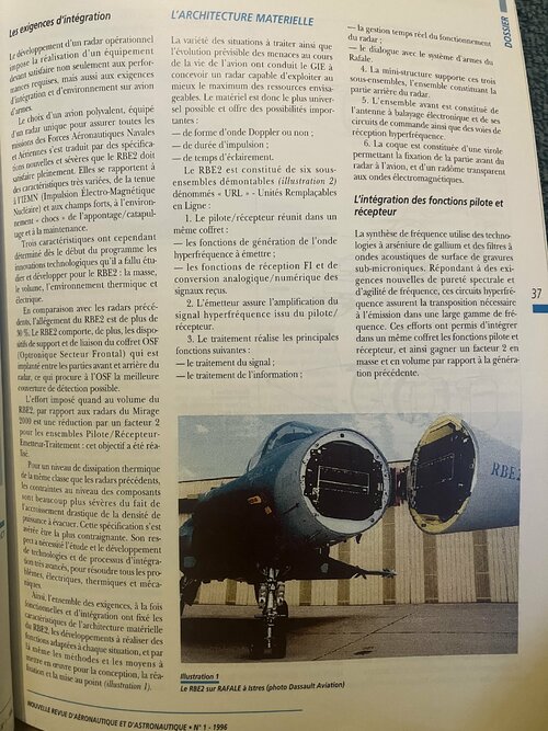
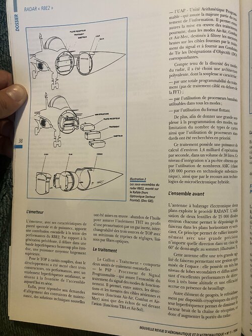
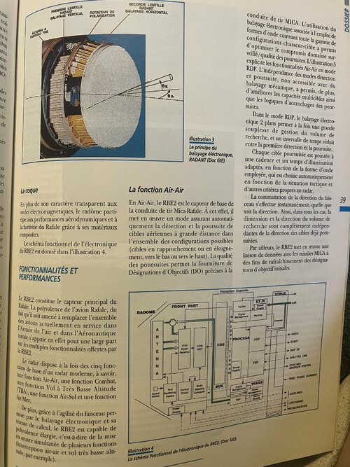
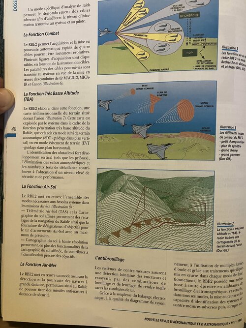
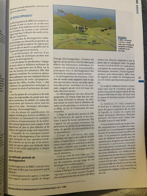
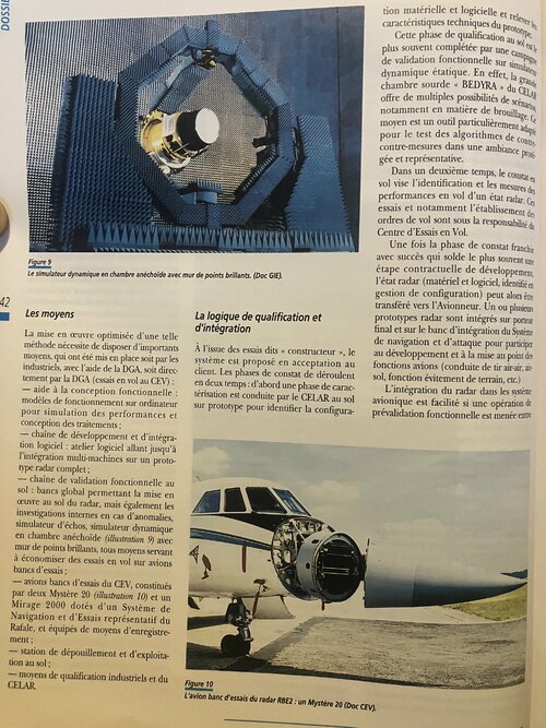
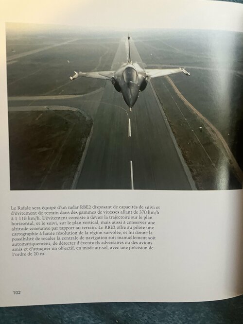
NT CASE THE "RBE2" RADAR OF THE RAFALE COMBAT AIRPLANE Philippe RAMSTEIN and Max SCHUMPERLI THE RAFALE SHOULD ULTIMATELY REPLACE ALL THE AIRCRAFT CURRENTLY IN SERVICE IN THE AIR FORCE AND IN NAVAL AERONAUTICS, IT WAS NECESSARY TO PROVIDE IT WITH A RADAR COMBINING ALL THE FUNCTIONALITIES OF THE SPECIALIZED RADARS OF PREVIOUS GENERATION • THE RBE 2 - RADAR WITH ELECTRONIC SCANNING 2 PLANES - MEETS THIS AMBITIOUS OBJECTIVE OF VERSATILITY • Max SCHUMPERLI, ISEN Engineer, is Deputy Director of the Detection Division of DASSAULT ÉLECTRONIQUE. 35 Philippe RAMSTEIN, X-ENST engineer is director of the “Elancourt” radar programs at the THOMSON-CSF Radars & Contre-mesures subsidiary. THE RBE 2 PROGRAM signal and information, materials, subassemblies; The implementation of the RBE2 program was the result of a long preparation since already at the beginning of the 80s, the need to have a common radar for all missions was taking shape. This need has led to a search in emerging technologies for solutions to meet this need: electronic scanning antenna, very high-speed integrated circuits, composite materials, etc., which has led to the launch of a series of actions with the help from the DGA: — exploratory developments to validate in flight, on models, the new concepts. The development of the RBE2 was entrusted at the end of 1988 to the GIE Radar ACT/ACM RAFALE, bringing together the companies Thomson-CSF (for 2/3) and DASSAULT ELECTRONIQUE (for 1/3), which was notified to the end of 1989 the development work on the RBE2. Since then, many important milestones have been reached: mid 1989: start of development work - upstream studies in the field of components, processing algorithms prototype development; RADAR «RBE2> enemy jamming, but also radiation from friendly systems. - the possibility of developing a multi-sensor tactical situation, the role of which is to provide knowledge of the military environment; - end of 1991: acceptance of the first prototype These requirements set the main functional characteristics of RBF2: — taking into account the performance required, the need for a 2-plane electronic scanning antenna and a high-performance transmission-reception chain; - given the wide variety of missions assigned, the need for numerous operating modes leading on the one hand to high programmability of its sub-assemblies and to powerful processing, on the other hand to a very significant development software development. CASE RBE2: -July 1992: 1st prototype RBE2 flight on Airplane Mystery 20 Test Bench; -July 1993: 1st prototype RBE2 flight on a Rafale aircraft; - August 1994: launch of the industrialization phase. - an ability to blindly penetrate enemy territory with a good level of survivability; - an ability to implement Air-Air, Air-Ground and Air-Sea multi-target fire control. All of these features should be The release of the first series radar is scheduled for February 1997. The development of radar operating modes, characterized by the creation and development of software installed on the prototype radars, is being carried out gradually. The fine-tuning of all operating modes must continue in line with the development of operational standards. robust; they must be able to be implemented day and night in various meteorological conditions, and a dense electromagnetic environment: Glossary RAFALE INTEGRATION Tactical Fighter / Marine Fighter Application Specific Integrated Circuit •ACT/ACM • ASIC Armament Electronics Center (located in Bruz) Flight Test Center • CELAR What is the need? • BODY • CAD/CAM Computer Aided Design and Manufacturing The Rafale is intended to replace the Jaguars, Mirage F1s and eventually the first-generation Mirage 2000s in the Air Force, and the Crusaders and Super-Etendards in the Navy. • DGA General Delegation for Armaments • DO Designation of Objectives • POSSIBLY Terrain Avoidance • FFT Fast FOURIER Transform • BE Intermediate Frequency This is why, operationally, the system must be capable, alone or on patrol, of ensuring missions in post-2000 enemy environments: - defense and air superiority; GIE •IEMN Economic Interest Grouping Nuclear Electromagnetic Pulse Front Sector Optronic Interception, Combat and Self-Protection Missile • MICA • OSF Programmable Signal Processor • PSP •RBE2 2-Plane Electronic Scanning Radar Range Finder and Tracking - attacking valuable land targets; • RDP hostile tory • SDT Very Low Altitude Terrain Following -storming at sea; • TBA - fire support on the ground. • THT Very High Voltage To achieve all of these versatility objectives, the Rafale system offers both: • TOP Traveling Wave Tube • STEAM Programmable Arithmetic Unit Line Replaceable Unit • URL ADVANCED TECHNICS AND TECHNOLOGIES assembly unit is composed of a microwave receiver cooled by cryogenic device as well as electronic scanning antenna including 2 dielectric lenses with more than 50 000 diodes. This antenna provides an accurate beam agility with a low sidelobe level. As a result, all the air mission spectrum is covered. automatic multitarget Thanks to specific trackings are independent of detection. Fired missiles can be updated with target data sent by data link up to the multitarget combat modes. ABSTRACT processing, waveform management and diagram quality, RBE2 considerably reduces the jammer effects in the main functions which can also be simultaneous. RAFALE integration and environment contraints have led to innovate in many directions: the mass In Very Low Level Flight function, a 3 dimensional map is sent to the aircraft system to perform blind penetration with high level of security. decreases by 30%, the volume is divided by 2 and thermic and electric performance is higher. The exciter-receiver includes GaAs submicronic components as well as acoustic wave filters, the transmitter uses a TWT working in a wide band with a large dynamic, the forward After 6 year development, the RBE2 has won the taken up challenges and production line is due to begin in 1997. Moreover, in the future, this background will optimize preliminary thoughts about integration requirements, performance specifications and cost mastery. In Air to Surface function, multitarget RBE2 provides detection and tracking of war ships as well as ranging or very high resolution maps of ground targets. COMPLETE OPERATIONAL FUNCTIONS In Air to Air function, contrary to mechanical radar, NEW JOURNAL OF AERONAUTICS AND ASTRONAUTICS N° 1-1996 Integration requirements The variety of situations to be dealt with as well as the foreseeable evolution of threats during the life of the aircraft led the GIE to design a radar capable of making the best use of the maximum possible resources. The material is therefore as universal as possible and offers significant possibilities: The development of an operational radar requires the production of equipment that must satisfy not only the required performance, but also the weapon integration requirements. and environment on aircraft - dialogue with the Rafale weapons system. 4. The mini-structure supports these three subassemblies, the assembly constituting the CASE rear part of the radar. 5. The front assembly consists of the electronically scanned antenna and its control circuits as well as microwave reception. that ways of The choice of a multi-purpose aircraft, equipped with a single radar to ensure all the missions of the Naval and Air Aeronautical Forces has resulted in new and severe specifications that the RBE2 must fully satisfy. They relate to a wide variety of characteristics, from resistance to IEMN (Nuclear Electro-Magnetic Pulse) and strong fields, to the “shock” environment of the landing/catapulting and to the maintenance. -of Doppler waveform or not; 6. The shell is made up of a ferrule allowing the front part of the radar to be fixed to the aircraft, and a radome transparent to electromagnetic waves. pulse duration; illumination time. The RBE2 consists of six removable sub-assemblies (illustration 2) called "< URL" - Replaceable Units The integration of pilot functions and Online: 1. The pilot/receiver unites in the same box: receiver Frequency synthesis uses gallium arsenide technologies and sub-micron etched surface acoustic wave filters. Responding to new requirements for spectral purity and frequency agility, these microwave circuits ensure the transposition necessary for transmission in a wide frequency range. These efforts have made it possible to integrate the pilot and receiver functions in the same box, and thus save a factor of 2 in mass and volume compared to the previous generation. However, three characteristics determined from the start of the program the technological innovations that had to be studied and developed for the RBE2: mass, volume, thermal and electrical environment. the functions for generating the microwave to be transmitted; the functions of IF reception and analog/digital conversion of the signals received. 37 2. The transmitter amplifies the microwave signal from the pilot/receiver. In comparison with previous radars, the weight reduction of the RBE2 is more than 30%. The RBE2 also includes support and connection devices for the OSF box (Optronics Frontal Sector) which is installed between the front and rear parts of the radar, which gives the OSF the best possible detection coverage. 3. The processing performs the following main functions: - signal processing; - information processing; The effort imposed on the volume of the RBE2, compared to the Mirage 2000 radars, is a reduction by a factor of 2 for the Pilot/Receiver-Transmitter-Processing assemblies: this objective has been achieved. JRBE For a level of heat dissipation of the same class as the previous radars, the constraints at component level are much more severe due to the drastic increase in the power density to be evacuated. This specification turned out to be the most restrictive. Compliance with it has required the study and development of very advanced technologies and integration processes, to solve all the problems, electrical, thermal and mechanical. Thus, all of the requirements, both functional and integration, have fixed the characteristics of the RBE2 hardware architecture, the developments to be carried out of the functions adapted to each situation, and thereby the methods and means to implement work for the design, production and development (illustration 1). To Illustration 1 The RBE2 on RAFALE at Istres (photo Dassault Aviation) NEW JOURNAL OF AERONAUTICS AND ASTRONAUTICS N° 1-1996 RADAR «RBE2>> PLOT RECEIVER TREATMENT CASE PART Given the diversity of radar modes, a versatile architecture was chosen, the flexibility of which is characterized -by total processing programmability (no hard-wired processing outside of TFF); - by the use of unmarked processors - usable in all modes; - by using the floating format. STRUCTURE Furthermore, in order to give great flexibility to the programming of the modes, a limitation of the number of types of cards as well as the use of standard processors have been sought as a priority. RECEIVER DRIVE TREATMENT The 38 AND This processing has a computing power of approximately 1.4 billion operations per second, in a volume of 38 liters. This level of integration could only be obtained by using numerous ASICs (class 100,000 gates in sub-micronic technology), as well as by resorting to hybrid microelectronic technologies. of the J d Illustration 2 The subsets of F RBE2 radar, mounted on the Rafale (excluding Sector Optronics P The front set Frontal). (Doc GIE). The two-plane electronically scanned antenna uses the RADANT process. The union of two lenses of approximately 25,000 diodes each allows the beam to be depointed in the horizontal and green planes. This principle makes it possible to instantly reach any direction with great precision in a cone of 60° half-angle at the vertex (illustration L The transmitter R have been implemented: abandonment of oil to ensure EHV insulation in favor of pressurization by an inert gas, interchangeability of the three TOP sources with a minimum of adjustment adjustments, fiber optic links . The transmitter, with its spectral purity and power characteristics, makes an essential contribution to maintaining the performance of the RBE2. Compared to the previous generation, it delivers in a much wider microwave band, a much higher average power. d S P The treatment This antenna offers very high beam ag lity allowing ope mized space management: it has a very low level of secondary and diffuse lobes, excellent detection performance at very low altitude and increased efficiency in the presence of jamming. The Processing Unit comprises two essential processing units: - the PSP - Programmable Signal Processor which handles all the processing of the operating mode signal. It allows, among other things, the detection and measurement of air and sea targets (Air-Air, Combat and Air-Sea functions) as well as ground echoes in front of the aircraft (TBA and Air-Ground functions). For the TOP with coupled cavities, the development of which was carried out by three manufacturers, these performances, with satisfactory microwave efficiency, are at the border of what is currently available in series. in A Finally, to respond to requests for alleviation of maintenance constraints, new technical solutions Another element of progress, the cooling by cryogenic devices of the microwave receiver makes it possible to reduce the noise factor of the reception chain, thus increasing the range of the radar. NEW JOURNAL OF AERONAUTICS AND ASTRONAUTICS N°1-1 FIRST VERTICAL SCAN RADANT LENS POLARIZATION ROTATOR ram- MICA fire control. The use of electronic scanning associated with the use of waveforms covering the whole range of fighter-target configurations has made it possible to optimize the compromise monitored domain/tracking quality. Illustration 5 explains the Air-Air functionalities in RDP mode. The independence of the detection and tracking modes, not accessible with mechanical scanning, has also made it possible to improve the multi-target capacities as well as the tracking lock-up logics. male between FIXED BEAM ANTENNA CASE ents bal res do- ites 00) BE of the NOT ure with: In RDP mode, electronic 2-plane scanning allows both great flexibility in managing the search volume, and a reduced time interval between the first detection and tracking. A little of Illustration 3 you are The principle of electronic scanning, RADANT (Doc GIE). Each tracked target is pointed at an appropriate rate and illumination time, depending on the waveform used, which is chosen automatically depending on the tactical situation and other criteria specific to the radar. Of- it is is The Air-Air function Shell an- Beam direction switching is instantaneous, regardless of direction. Thus, in all cases, the size and direction of the search volume are completely independent of the direction of the targets already being tracked. 39 In Air-Air, the RBE2 is the basic sensor of the Mica-Rafale fire control. To this end, it implements a mode that automatically detects and tracks aerial targets at long distances in all possible configurations (targets approaching or moving away, downwards or upwards). . The quality of the pursuits allows the provision of precise Target Designations (DO) to the In addition to its transparent nature to electromagnetic waves, the radome contributes to the aerodynamic performance and stealth of the Rafale thanks to its composite materials. of ns This as well with The block diagram of the RBE2 electronics is given in Figure 4. In addition, the RBE2 implements a data link with the MICA missiles for the purpose of refreshing the initial target designations. 0 FEATURES AND PERFORMANCE Reception Channels The RBE2 is the Rafale's main sensor. The versatility of the Rafale aircraft, from the fact that it is required to replace all the aircraft currently in service in the Air Force and in Naval Aviation, is in fact based to a large extent on the multiple functionalities offered by the RBE2. STRUC EX /R AIR Power Supply FRONT PART Exciter WE FOUND S Digital Receiver Management Channel and ANTENNA VIDEO It is PROCESS PSP START FOS Cryo Hyper Receiver AS UNITED BUS B2 The radar has at the same time the five basic functions of a modern radar, namely, an Air-Air function, a Combat function, a Flight at Very Low Altitude (TBA) function, an Air-Ground function and a Air-Sea function. r SPECTRA LINK PDP n SYNCHRO AVIONICS SYSTEM S Power Supply m -TREE-PHASE CURRENT TRANS Power BUS Beam Steering Computer Digital Management Test Switching Device Control Circuit Management COOL Guard Ants COOLANOL Supply In addition, thanks to the agility of the beam enabled by electronic scanning and its calculation speed, the RBE2 is capable of extended versatility, i.e. of placing (air-to-air interception and very low flight simultaneous work of several study functions, for example). TWT CRYOGENIC PRESSURIZATION Power Supply Illustration 4 The block diagram of the RBE2 electronics. (GIE document). specific raid analysis mode allows enemy targets to be counted in order to improve the level of information transmitted to the system and to the pilot. DOSS RESEARCH THE PROSECUTION 17 PROSECUTION IN THE VOLUME IA RESEARCH The Combat Function PROSECUTION LIAISONS MISSILE AIRPLANE PROSECUTION The RBE2 provides fast automatic acquisition and tracking of four highly scalable targets. Several acquisition patterns are available, depending on the location of the targets. The parameters of the targets being tracked are transmitted to the system for the implementation of the MAGIC 2, MICA-IR and Canon fire controls (illustration 6). MULTI-CHASES Illustration 5 The air-to-air functions of the RBE 2 radar: the distance search and tracking mode (Doc. GIE RDP EVALUATION PRIORITY LIST RAID ANALYSIS RADAR DOMAIN SMALL CONICAL DAMP PLAN DE SYMMETRIE The Very Low Altitude Function (TBA) GRAND CONICAL FIELD In this function, the RBE2 produces a three-dimensional map of the terrain in front of the aircraft (illustration 7). This map is used by the system as part of the very low altitude penetration function of the Rafale, whether in automatic terrain following mode (SDT-guidance in vertical plane) or in terrain avoidance mode (EVT -guidance in horizontal plane). Illustration 6 40 LARGE DEPOSIT The various modes of combat of the RBE 2 small conical field plane of symmetry - large field - large bearing (Doc GIE). The identification of obstacles with strong vertical development (such as pylons), the elimination of atmospheric echoes and numerous failure tests contribute to obtaining a high level of safety and performance. The Air-Ground Function The RBE2 implements all the modes necessary for the system requirements in Air-Ground missions (illustration 8): Air-Ground Telemetry (TAS) and refined ground mapping allowing Rafale navigation readjustments and the supply of target designations for the firing of Air-Ground weapons with maximum precision ; Illustration 7 The “very low altitude” (TBA) function: the radar produces a 3D map of the terrain in front of the aircraft (GIE Doc). High resolution ground mapping allowing, in addition to the functionalities of the refined ground mapping, to contribute to the precise identification of the objectives. anti-jamming nally, to the use of multiple waveforms and thanks to the specific processing implemented in each mode of operation, the RBE2 has foolproof electromagnetic jamming, in all its modes, the implementation and a robust in an environment of capabilities for identifying adversary countermeasures systems then, when c these and delays. The Air-Sea Function Countermeasures systems provide remote detection of transmitters and attempt, through combinations of jamming and decoys, to render firing lines ineffective. The RBE2 implements a mode ensuring the detection and tracking of ships at long range, thus allowing the Rafale to be able to fire anti-ship missiles from a safe distance. Thanks to the flexibility of electronic scanning, the quality of the ray diagram NEW JOURNAL OF AERONAUTICS AND ASTRONAUTICS N°1-1996 will have been triggered, minimizes the inconvenience caused. CASE DEVELOPMENT The development of RBE2 is complex and requires the implementation of many techniques. To control all the aspects, it is necessary to resort to a rigorous method whose effectiveness of the tools is established. THAT ons air-r DMT 2: the mod blessed by experience. The process of industrial development Illustration 8 in distant TELESCOPE The RBE2: the “Air-Ground” function: modes SEE AFF. DOPPLER (Doc G a progressive approach, at the triel favors the course of which the control of the sensor itself is ensured in parallel with the s functional aspects. mastery of radars for navigation readjustment and ground target attack (GIE Doc). TAS TELEMETRIE AIR-SOL DMT DETECTION DE MOBILES TERRESTRES The problem of mastering a large number of techniques persists throughout development: - during the specification phases, the team electromagnetic energy, to emit signals, to receive them and to process them to deliver synthetic information. The sensor is made up of main sub-assemblies whose development involves numerous trades; - the development of functions, i.e. modes are developed, implemented and developed in the radar computer. A large number of CAD/CAM tools are required for the design of sub-assemblies: mechanical structures, antennas, microwave circuits, electronic boards, ASICs. For the software, the development workshops were carried out specifically for the project. responsible for the technical definition of the radar, in cooperation with the DGA, based on user needs. It must also model the many physical phenomena that are involved in the operation of the radar (propagation, target response, clutter, noise, etc.) in order to develop the technical specifications and guide the choices of architecture of the mate. - riel; 6 41 nts mode say radar modes implanted in the sensor, each of which performs a specific operational task: air/air surveillance, tracking, air-ground imagery, flight at very low altitude, air-sea detection. you RBE 2 conical mp The production tools must communicate with the design tools, to eliminate any break point in the flow of data defining the radar. This limits the risk of erroneous data and loss of time. metrics mp ement The development follows a progressive approach, where each stage must be validated before tackling the next one. Indeed, any backtracking in the definition of the radar is very penalizing in terms of costs and delays, due to the overlapping of the sub-assemblies. - during the design and construction phases, the project managers have to coordinate the trades, because of the interactions that exist between all the aspects of a radar: thermal, mechanical, electrical, electromagnetic, etc. , Validation of the radar begins first with the validation of the characteristics of the sensor itself, during which we ensure compliance with the mechanical, electrical, electromagnetic and thermal clauses for each sub-assembly and for the radar. integrated. - during the qualification phases, the technical teams must model and reproduce in the laboratory the multiple environmental conditions of reality. They must also take into account an increasingly sophisticated algorithm and large volumes of real-time software. The specification stage enables the architecture of the sensor and the functions to be defined, based on the operational need. It is based on theoretical models which make it possible to predict the performance of the radar, to specify its sub-assemblies and to dimension them. It is only then that we can gradually approach the functional qualification because it is practically impossible to test all the modes of a radar at once. This is why the planning of the functional validation tests must be organized to progress by operating states with increasing performance (incremental development). This makes it easier to identify any faulty functions. Processing validations are carried out in a real-time environment representative of the real radar environment; experience shows that it is possible to simulate on the ground behavior similar to that encountered in flight, limiting the adjustments to be made at the end of the flight. All of these constraints show that the development of a new airborne radar is a heavy operation. It only leads to success if those involved have implemented a rigorous method and appropriate tools at each phase of the project. very b The sub-assembly design stage uses modeling, implementation and analysis tools. Experience shows that these tools must form a coherent workshop for working on common data, and exchanging results. CHARM it's a 30 d simulation states. It is during this stage that we The general method of development introduces innovations that have been validated by models (an obligatory step for any technological development). The development of the RBE2 is based on two axes of effort which are pursued in parallel: - the development of the sensor, i.e. The step of producing the sensor consists of manufacturing the sub-assemblies, grouping them together and developing them. At the same time, the software for implementing the various of one hardware support capable of directing NEW JOURNAL OF AERONAUTICS AND ASTRONAUTICS N° 1-1996 FILE Secondly, in-flight observation aims to identify and measure the in-flight performance of a radar condition. This testing and in particular the establishment of flight orders are the responsibility of the Flight Test Center. Once the observation phase has been successfully completed, which most often completes a contractual development stage, the radar status (hardware and software, identified in configuration management) can then be transferred to the Aircraft Manufacturer. One or more radar prototypes are integrated on the final carrier and on the navigation and attack system integration bench to participate in the development and fine-tuning of aircraft functions (air-to-air, air-to-ground fire control, terrain avoidance function, etc.) Figure 9 The dynamic simulator in an anechoic chamber with wall of shining points. (GIE document). 42 The means The logic of qualification and integration The optimized implementation of such a method requires significant resources, which have been put in place either by manufacturers, with the help of the DGA, or directly by the DGA (flight tests at the CEV ): At the end of the so-called "manufacturer" tests, the system is offered for acceptance to the customer. The observation phases take place in two stages: first, a characterization phase is conducted by CELAR on the ground on a prototype to identify the configuration The integration of the radar into the avionics system is facilitated if a functional pre-validation operation is carried out between functional design assistance: computer operating models for performance simulation and treatment design; software development and integration chain: software workshop going as far as multi-machine integration on a complete radar prototype; functional validation chain on the ground: global benches allowing the implementation of the radar on the ground, but also internal investigations in the event of anomalies, echo simulator, dynamic simulator in an anechoic chamber (illustration 9) with wall of bright points, all means used to save flight tests on aircraft test benches; - CEV test bench aircraft, consisting of two Mystère 20 (illustration 10) and a Mirage 2000 equipped with a Navigation and Test System representative of the Rafale, and equipped with recording means; ground processing and processing station; - industrial and CELAR qualification means. Figure 10 The RBE2 radar test bench aircraft: a Mystery 20 (CEV Doc). - retains significant development potential. - future operational needs and international competition, requires a permanent investment effort in terms of development tools and in coherence with the long capitalized experience. the Aircraft Manufacturer and the Bodybuilder: using a so-called functional pre-validation bench, the Bodybuilder validates with the Bodybuilder the dialogue and the System commands between the radar and the aircraft, the command sequences being provided by the Aircraft Manufacturer. Indeed, the hardware and software architecture of the RBE2 assembly has been sized to be able to accommodate all the functionalities planned for the three Rafale darts defined to date. It also includes provisions in terms of memory and computing capacity for new modes that the inevitable evolution of the operational context will make necessary. These efforts will enable better control of development costs and a reduction in production costs. WHERE ARE WE ? OUTLOOK References The experience acquired on the development of the RBE2 has clearly shown that the overall cost constraint - development, - industrialization, series - must be a basic factor taken into account as far upstream as possible. the [1] ROUSSEAU G. (Senior Weapons Engineer). RBE2: The Rafale radar, After six years of development work, the technical bets of the RBE2 have been won: the current industrialization phase will lead to the delivery of production radars from 1997. L'ARMEMENT n° 47-Mai-June 1995. [2] GILON B., SCHUMPERLI M. A current example: The RBE2 radar of the Rafale, Science and Defense 1996. This overall cost is directly linked to the initial requirement specifications that [3] PLANTIER B., CHABOD L. Control either in terms of functionalities/performance of the development of airborne radars: requirements or in terms of integration constraints with the carrier aircraft (volume, mass, thermal, etc.), as well as the maturity of the technologies used. Thanks to the major principles adopted, high-tech modular hardware, variety of operating modes, rigorous design and development methods, the RBE2: methods and tools, Science and Defense 1996. [4] MATHA J. The Rafale weapon system: versatility, flexibility, robustness. New Review of Aeronautics and Astronautics n° 2-1994, pp. 29 to 38. - meets Rafale integration requirements; 43 - allows for each operational situation, to have the best adapted solutions; Finally, it should be remembered that maintaining airborne radar development capabilities to meet the
 

Attachments

  • IMG_8616.jpeg
    IMG_8616.jpeg
    2.2 MB · Views: 35
  • IMG_8617.jpeg
    IMG_8617.jpeg
    2.2 MB · Views: 44
  • IMG_8618.jpeg
    IMG_8618.jpeg
    2.4 MB · Views: 46
  • IMG_8619.jpeg
    IMG_8619.jpeg
    2.4 MB · Views: 50
  • IMG_8620.jpeg
    IMG_8620.jpeg
    2.6 MB · Views: 52
  • IMG_8621.jpeg
    IMG_8621.jpeg
    2.5 MB · Views: 51
  • IMG_8622.jpeg
    IMG_8622.jpeg
    2.7 MB · Views: 45
  • IMG_8623.jpeg
    IMG_8623.jpeg
    2.6 MB · Views: 49
  • IMG_8624.jpeg
    IMG_8624.jpeg
    2.2 MB · Views: 59
I have a safety-related question. Apparently, SPECTRA uses jammers, which antennas are mounted, inter alia, quite close to the cockpit. Scorpion82 reported that "Pencil thin jamming beams are directed towards threat emitters." I understand that these are high RF energy beams. How do they affect the health and well being of the crew? Are they safe to the pilots?
 
I have a safety-related question. Apparently, SPECTRA uses jammers, which antennas are mounted, inter alia, quite close to the cockpit. Scorpion82 reported that "Pencil thin jamming beams are directed towards threat emitters." I understand that these are high RF energy beams. How do they affect the health and well being of the crew? Are they safe to the pilots?
The ECM antenna arrays aren't pointing towards the cockpit. The front arrays are angled away from the cockpit and are mounted on the canard roots. They utilise electronic scanning for beam shapening and positioning.
 
Thank you for the reply. Could you please clarify if these canard root antennas are used for reception or transmission? If the latter, what is the approximate RF power or pulse emanating from them during ECM operation? Is this still safe to the crew that sits within two yards from this array?
 
They are transmission antennas, probably including a receive capabiluty as well. They are apparently save enough as far as aircrew health is concerned. For the rest I can't tell you.
 
Guys, they act as receiver by interphasing. There is no added risk for the crew in this semi-passive mode.

Interphasing is at the heart of most western aircraft with data fusion.
 
The emmission from the Spectra aperture would be relatively small anyway. In number of Watts to tens of watts. To further protect the crew and cockpit electronics. The canopy would almost certainly be coated with reflective materials. e.g Gold. Which very likely to be so as It also helps reduce RCS.
 
Thank you for the information. I am curious if mere tens of Watts from Spectra can defeat semiactive radar guided missiles, when the tracking radar can emit kilowatts of RF power?
 
Technique RBG: a radar for the "Rafale" In our first report from the Paris Air Show, we published initial information on the RBG, Thomson-CSF radar and Serge Dassault Electronics which will equip the ACT and ACM, i.e. the production versions of the "Rafale ". A state-of-the-art program, with a very tight schedule: the prototype will be tested in flight from the end of 1991. he RBG, of modular design, comprises four elements: - the passive scanning antenna two-plane electronics with conventional pro-transmitter (and not the famous modules with both transmitter and phase shifter distributed over the entire surface of the active antennas). The antenna is made up of two elements: the illuminator (broadband antennas involving radiation adapted to the lenses) with three channels plus one for deviation measurement associated with an ancillary antenna; two crossed lenses, each formed by stacking phase-shifting channels, each acting with a mode-shifter, the whole allowing control of the brush. Ground tests are now underway for the Radant process and fully consistent with the Rafale program”. RBG - The traveling wave tube transmitter, liquid cooled, capable of delivering the power adapted to the various modes and the various types of recurring frequencies. - the receiver which generates a wide emission band, a high number of emission frequencies and a wide spectral band. The highly dynamic receiver can detect targets over an extremely wide range of ground clutter. Combined with the microwave receiver, this receiver allows RBG, multi-purpose electronically scanned array radar. It is multi-pursuit multi-target also the detection of targets with a very small radar cross section. air-to-air, has tracking capabilities and terrain avoidance in air-ground, remote detection in air-sea. Below is terrain tracking and avoidance: the - the processing unit which allows the processing of the radar signal, information and radar mapping with a single URL (line replaceable unit), The processing of the radar signal is done with a Programmable signal processor with a power of one gigaflop, high power allowing excellent performance in CCME. radar representation. The technologies used for the RBG, at a very high level, make use of large hybrid modules with CEMOS-type components of the order of one micron. The use of this level of integration required very advanced studies in connection technology. On the other hand, all the processors are programmable in real time and the software stored on downloadable mass memories. On the maintenance front, the RBG has an integrated test set that covers an increased number of failures allowing for two-tier ground maintenance, on-track with immediate replacement of URL modules, second-line with redundancy of the PSP structure, which allows operation and reconfiguration of the system, allowing the continuation of a mission despite the breakdown of numerous elements of the system. Aviation International 988 (15-7-89) safety of use which is added to that acquired by the specific work of development of the intrinsic reliability of the components. internal or external sensors of the aircraft, to carry out in parallel with the air/ground or air/surface mode, without interruption, an air/air search. In air/air, finally, the RBG, a multitrack radar, is capable of intercepting all sectors, all elevations and all altitudes. des (high, medium and low recurrence frequencies), thereby reducing the pilot's workload. In tracking mode, an automatic multitrack search can be carried out in parallel without pilot intervention by successive pointings in space thanks to electronic scanning, while retaining the tracking mode of the acquired targets. Finally, the RBG of the Rafale will also have a tactical situation assessment mode. is RBG: versatility ui of To do this, the RBG has search, pursuit and tactical situation assessment modes. In search mode, it is primarily able to detect Without wanting to go into technical details, it should be remembered that the Rafale's radar works both in air/surface and air/ground modes as well as air/air. In air/surface, optimized mode with the specific treatment of sea clutter, the RBG carries out a long distance, multitrack search and with an analysis of the targets; the performances making it possible to largely cover the fields of use of the most efficient stand-off missiles. In air/ground, the RBG allows intervention at all times, whatever the weather with terrain avoidance capabilities (tracking on the horizontal plane), terrain saivi (tracking on the vertical plane) and avoidance of threats. The pilot will have a three-dimensional radar map displayed on his head-up display which can be superimposed on the terrain landscape. The different operating modes of the RBG radar in the air/ground include very high definition radar mapping (possible navigation readjustment and all-weather designation of land targets- On the right, the TCR antenna, Thomson-CSF Radant. Below is the expanded versatility: air-to-air and terrain-follow-and-avoid mode simultaneity. is only with different modes: raid analysis (automatic enumeration of targets by the radar even if the scope does not allow it; fine analysis of the enemy device commanded by the pilot), identification (Nato Identification System mode); establishment and presentation to the pilot of a list of priorities with display of the eight most dangerous targets with specific symbology (speed and distance). Presented automatically to the pilot, this list can be modified at any time by the pilot according to the situation. As we can see, with the RBG, the “Rafale should have a versatile, very high-level radar, enabling it to compete with its competitors. Moreover, contacts are maintained for a possible cooperation with the EFA radar manufacturers. the MULTITRACK SEARCH TBA tres), a search and tracking mode for land mobiles, another for fixed targets and a classic range finding mode. Finally, as for the air/surface mode, the RBC responds, in air/ground, to the concept known as extended versatility. Concept which allows (thanks to the scanning speed and beam agility of the electronically scanned antenna), in the event of external threats unveiled by hostiles approaching whatever their altitude (look down) over greater distances than those of the other modes, this is a pre-detection mode. In the face-to-face interception phase, the next step, after the pre-detection, is the multitrack search with display of the distances of the targets, in addition to that of the speed, thanks to the use and the automatic management of the three on- JLP Aviation International 988 (15-7-89)
 

Attachments

  • IMG_9485.jpeg
    IMG_9485.jpeg
    2.5 MB · Views: 41
  • IMG_9484.jpeg
    IMG_9484.jpeg
    2.5 MB · Views: 45
Thank you for the information. I am curious if mere tens of Watts from Spectra can defeat semiactive radar guided missiles, when the tracking radar can emit kilowatts of RF power?

Deceptive jamming does not need lot of power tho. All it needs to do is to replicate and modify the victim radar signal in a manner which will induce break lock condition or in some advanced technique like Cross Eye, error in pointing of the radar.
 
What mode tho ? I would expect it's just one among several "selectable" scan rates. for Phased arrays the scan rate can be precisely controlled by the computer according to the mode requirement.

---------

One question. Does French have other kind of datalink than NATO standard Link-16 ?
Found the origin of this claim “Pilotes de RAFALE”
The Rafale will be equipped with an RBE2 radar with terrain tracking and avoidance capabilities in speed ranges from 370 km/h to 1,110 km/h. Avoidance consists in deflecting the trajectory on the horizontal plane, and the tracking, on the vertical plane, but also in maintaining a constant altitude with respect to the terrain. The RBE2 offers the pilot a high-resolution map of the region overflown, and gives him the possibility of recalibrating the navigation unit either manually or automatically, of detecting possible adversaries or friendly aircraft and of attacking an objective, in mode air-to-ground, with an accuracy of the order of 20 m. Above: in air-to-air mode, the Rafale radar has a range of 110 km for a speed search (Doppler effect) of 90 km. This equipment can scan a field of ± 70° in bearing and ± 60° in elevation, the scanning speed being 110°/s. Above all, it has a multi-target capability and is able to track up to eight objectives at a time.
 

Attachments

  • IMG_9719.jpeg
    IMG_9719.jpeg
    1.8 MB · Views: 31
  • IMG_9718.jpeg
    IMG_9718.jpeg
    1.5 MB · Views: 36

Attachments

  • IMG_8632.jpeg
    IMG_8632.jpeg
    2.2 MB · Views: 23
  • IMG_8633.jpeg
    IMG_8633.jpeg
    2.6 MB · Views: 26
  • IMG_8634.jpeg
    IMG_8634.jpeg
    2.4 MB · Views: 21
  • IMG_8635.jpeg
    IMG_8635.jpeg
    2.3 MB · Views: 22
  • IMG_8636.jpeg
    IMG_8636.jpeg
    2.5 MB · Views: 19
  • IMG_8637.jpeg
    IMG_8637.jpeg
    2.5 MB · Views: 17
  • IMG_8638.jpeg
    IMG_8638.jpeg
    2.4 MB · Views: 18
  • IMG_8639.jpeg
    IMG_8639.jpeg
    2.3 MB · Views: 18
  • IMG_8652.jpeg
    IMG_8652.jpeg
    2 MB · Views: 20
  • IMG_8653.jpeg
    IMG_8653.jpeg
    2 MB · Views: 21
  • IMG_8654.jpeg
    IMG_8654.jpeg
    2.5 MB · Views: 20
  • IMG_8655.jpeg
    IMG_8655.jpeg
    1.9 MB · Views: 20
  • IMG_8656.jpeg
    IMG_8656.jpeg
    2.4 MB · Views: 20
  • IMG_8657.jpeg
    IMG_8657.jpeg
    2.3 MB · Views: 17
  • IMG_8658.jpeg
    IMG_8658.jpeg
    2 MB · Views: 17
  • IMG_8659.jpeg
    IMG_8659.jpeg
    1.8 MB · Views: 14
  • IMG_8660.jpeg
    IMG_8660.jpeg
    2.3 MB · Views: 14
  • IMG_8661.jpeg
    IMG_8661.jpeg
    2.2 MB · Views: 14

Similar threads

Back
Top Bottom