
You are using an out of date browser. It may not display this or other websites correctly.
You should upgrade or use an alternative browser.
You should upgrade or use an alternative browser.
Dark Moon Rising: Archibald space TL
- Thread starter Archibald
- Start date
1994
NASA CHANGES PLANS – AND KEROSENE RETURNS
A decade ago the Air Force for practical reasons picked kerosene as the fuel of its Reusable Orbital Launch System (ROLS).
This, because kerosene is quite familiar to ground crews at every single air bases across the world; unlike liquid hydrogen.
The latter was initially prefered by NASA for its own rocketplane, called MUST: MUltipurpose Space Stransport. Not only the rockets but also the GE4 turbojets were to burn liquid hydrogen for pure energy.
This dogma however has recently be shaken; first, by ROLS early flights but also by a major rocket propulsion breakthrough from the former Soviet Union.
Much like Salkeld, Beichel and Bulman at Aerojet, the Soviets have long been interested in tripropellant rockets: kerosene fuel for max takeoff thrust; shifting to liquid hydrogen fuel pure energy during ascent; both burning liquid oxygen oxidizer.
Such engines however are complex and heavy as kerosene and hydrogen, being vastly different fuels needs separate combustion chambers and turbomachinery.
The Soviets however have made a groundbreaking discovery. What if kerosene was poured only in the exhaust and nozzle of an hydrogen rocket ? No more combustion chamber or turbopump: instead, a kerosene afterburner quite similar to the one of a fighter jet. This is called a Thrust Augmented Nozzle, and Aerojet bright trio of Salkeld, Beichel and Bulman recently got their company in a deal with the Soviets – Lozino Lozinskiy – to share the revolutionary engine technology.
And that's the exact moment when NASA rocketplane entered the picture: with kerosene returning to the forefront. The space agency noted that whatever the fuel (hydrogen or kerosene) it changed nothing to the suborbital refueling dance... as they both burn liquid oxygen oxidizer, which is the one and only fluid transfered.
While the mixture ratios are very differents (2.3 vs 6), the LOX transfer happen only after the engine shift to hydrogen fuel - so this is not an issue.
Indeed LOX/kerosene 2.3 O/F ratio would mandate, not only LOX but also kerosene refueling: vastly complicating the whole transfer. In stark contrast, hydrolox skewed O/F ratio of 6 only request LOX transfer.
Truth is that with or without suborbital liquid oxygen transfer, Thrust Augmented Nozzle already changes the SSTO paradigm - for the best. An alliance of the two technologies could result in pretty formidable rocketplane performance.
As a result it dawned on NASA Langley engineers that a combination of the two would be almost unstoppable. They lost no time in making preliminary study of a tripropellant MUST. Kerosene went to "wet" wing tanks: something not possible with hydrogen. As noted by Rockwell for their Star Raker spaceplane and also by the Soviets, kerosene wing tanks brings major structural and performance benefits.
Then a difficult decision had to be made, relative to the GE4 turbojets: hydrogen or kerosene fuel ? Tradeoff were performed. Fact was that shifting the turbojets back to kerosene made MUST as "airport-friendly" as the military rocketplanes. Because kerosene – not hydrogen - is present day ubiquitous fuel at every airstrip in the world. Hence, once the rocket engines returned to kerosene the turbojets just followed the move.
The end result is called by NASA a synergistic tripropellant system.
The new CONOPS is as follow:
1-Kerosene turbojets at takeoff - with hydrogen afterburners for massive thrust augmentation;
2-MIPCC up to Mach 4.5 - with LOX injected in front of the compressor;
3-transition from airbreathing to rocket engines: 30 degree climb
4-tripropellant rocket running on LOX/kerosene fuel first;
5-tripropellant rocket gradually shifting to liquid hydrogen fuel thereafters;
6-and finally: LOX transfer by a twin rocketplane with a refueling kit in the payload bay
As for performance, Langley intuition that a combination of LOX transfer and tripropellant would be unstoppable has proven right: beyond even the wildest expectations.
The end result is pretty exciting. Flocks of giant rocketplanes flying out of airports could haul enormous payloads all the way to cislunar space. And from there: into the inner solar system or... the Marius Hills."
...
Last edited:


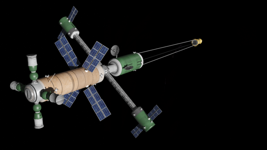
And space station Liberty, with its Big Gemini crewed cargo vehicle.

Liberty has the same basic architecture as OTL Mir: a four bladded propeller. Except the modules are 22-ft-diameter Skylab / S-IVB instead of 15-ft, Proton constrained.

Liberty has the same basic architecture as OTL Mir: a four bladded propeller. Except the modules are 22-ft-diameter Skylab / S-IVB instead of 15-ft, Proton constrained.
In that timeline Liberty and MKBS are close neighbourghs: not only the same 250 miles altitude, but also almost identical inclinations. This, courtesy of Skylab and... Baikonur access. So: same inclination of 52 degrees.
During Cold War, the situation looks like Berlin Wall in space.
After 1991, it will become an advantage rather than a liability.
During Cold War, the situation looks like Berlin Wall in space.
After 1991, it will become an advantage rather than a liability.

Scott Kenny
ACCESS: USAP
- Joined
- 15 May 2023
- Messages
- 11,628
- Reaction score
- 14,305
I thought that was the other way around IOTL? hydrogen as the afterburner fuel?The Soviets however have made a groundbreaking discovery. What if kerosene was poured only in the exhaust and nozzle of an hydrogen rocket ? No more combustion chamber or turbopump: instead, a kerosene afterburner quite similar to the one of a fighter jet. This is called a Thrust Augmented Nozzle, and Aerojet bright trio of Salkeld, Beichel and Bulman recently got their company in a deal with the Soviets – Lozino Lozinskiy – to share the revolutionary engine technology.
Also, I suspect that you're still going to need a kerosene turbopump, but you basically get a single turbine driving two separate compressor pumps.


"Life, uh, finds a way"
...
Per lack of a viable Reusable Launch Vehicle concept, by 1965 affordable access-to-space had to find a different way.
First generation: air launching Agena (max: 10 000 pounds)
Second generation: air launching Titan stage 2 (max: 20 000 pounds)
Because air-launch had reached its limits the third generation took a different path: Titan's 120 inch, 7-segment booster.
And in passing, it snatched the hydrogen stages - Centaur, S-IVB - that were too big for air launch.
The LR91-Agena two-stage booster is the pivot of all three generations.
It started as the upper tip of Titan IIIB: classic expendable launch vehicle; ICBM legacy.
Then it was hanged to a B-52 wing pylon: for air launch.
Finally it returned to vertical launch, but this time on top of a 1207 solid-fuel booster. It's the entry level of the SATAN launch vehicles: overlapping with air-launch.
Meanwhile some unexpected breakthroughs happened on the RLV front...
Folks, just for the fun of it I have compiled a tentative roadmap out of a pile of NASA documents.
MANNED PLANETARY EXPLORATION ROADMAP - FOR THE 1970'S AND BEYOND
-November 1973: launch of a manned Venus flyby (end: december 1974)
-June 1975: launch of a manned asteroid flyby (Geographos or Toro - end: november 1976)
-January 1977: launch of a triple planetary flyby (returns: December 1978)
-March 1980: launch of a manned Venus orbit mission (returns: late 1981)
-November 1981: launch of a manned trip to Phobos and Deimos (returns: August 1983: those are von Braun' 69 Mars dates)
-March 1985: launch of a manned Mars landing (lands in April 1986,returns: November: Baxter's Voyage own dates)
Nota bene: this is very optimistic, obviously. Notably considering Skylab 84 days missions OTL... 1973-74. Yet that manned Venus flyby was to use wet workshop tech, and this was once to launch much earlier than Skylab: AAP was to start in 1969. So there would have been some long duration & wet workshop data by late 1973...
 www.wired.com
Unlike Skylab that was pushed to 1972-73-74, AAP-1's wet workshop was to start late 1968. Since it was (supposedly) a dirt cheap space station, it could run in parallel with the lunar landings.
www.wired.com
Unlike Skylab that was pushed to 1972-73-74, AAP-1's wet workshop was to start late 1968. Since it was (supposedly) a dirt cheap space station, it could run in parallel with the lunar landings.
Starting from there, if wet workshop ops start late 1968, by late 1973 ( = Venus flyby) there would have been five year of experience. Interesting.
-November 1973: launch of a manned Venus flyby (end: december 1974)
-June 1975: launch of a manned asteroid flyby (Geographos or Toro - end: november 1976)
-January 1977: launch of a triple planetary flyby (returns: December 1978)
-March 1980: launch of a manned Venus orbit mission (returns: late 1981)
-November 1981: launch of a manned trip to Phobos and Deimos (returns: August 1983: those are von Braun' 69 Mars dates)
-March 1985: launch of a manned Mars landing (lands in April 1986,returns: November: Baxter's Voyage own dates)
Nota bene: this is very optimistic, obviously. Notably considering Skylab 84 days missions OTL... 1973-74. Yet that manned Venus flyby was to use wet workshop tech, and this was once to launch much earlier than Skylab: AAP was to start in 1969. So there would have been some long duration & wet workshop data by late 1973...
Assuming Everything Goes Perfectly Well: NASA's 26 January 1967 AAP Press Conference
Usually in Beyond Apollo I devote most of my attention to technical documents and their historical context. I do not normally focus on press conference transcripts. The 26 January 1967 NASA Headquarters press conference led by George Mueller, Associate Administrator for Manned Space Flight, and...
Starting from there, if wet workshop ops start late 1968, by late 1973 ( = Venus flyby) there would have been five year of experience. Interesting.
Last edited:
APOLLO MAJOR END ITEMS (1977)
...
LM-8------Apollo 14 Fra Mauro
LM-9------Not flown, intended as Apollo 15, last H-class mission
LM-10-----Apollo 15 Marius Hills
LM-11-----Apollo 16 Descartes
LM-12-----Apollo 17 Taurus-Littrow
LM-13-----Apollo 18 Hadley
LM-14-----Not flown, intended as Apollo 19: dual launch, bicentenary day: Gassendi.
LM-15-----Not flown, considered as a logistics carrier for Apollo 19

Scott Kenny
ACCESS: USAP
- Joined
- 15 May 2023
- Messages
- 11,628
- Reaction score
- 14,305
The challenge with those is going to be radiation exposure, though I could see dragging 100 tons of water up into orbit to use as storm cellar shield plus extra.Boeing IMIS, 1968 - the study summary has a detailed list of launch windows.
"Nov 1981" is von Braun 1969 pitch to the Space Task Group.
"Apr 1985" is Stephen Baxter Voyage
View attachment 708703
I just agree with that statement.
They won't fly ITTL, it is more like nostalgia and rememberance.
Plus there are far, far better nuclear fission drives out there, than plain old solid-core NERVA.
Things like Fission Fragment Rocket and Pulsed NTR - or an alliance of the two. It is just a matter of the reactor energy hitting the hydrogen with the correct transmission of power. Fission fragments sucks, because thermodynamics. Which does not apply to fast neutron interactions with that hydrogen... this is PNTR.
And now that the fission fragments have lost their job of heating the hydrogen, then just shoot them straight out of a nozzle. This is FFR.
Both with decent thrust and unbelievable specific impulse: a good 500 000 seconds; 500 times better than old NERVA.
Bonus with PNTR: it derives from the TRIGA pulsing reactors: expressly designed by Teller and Taylor to be meltdown-proof.
Scott Kenny
ACCESS: USAP
- Joined
- 15 May 2023
- Messages
- 11,628
- Reaction score
- 14,305
And, as long as the reactor hasn't gone through first criticality before it's launched into space, it's minimally radioactive in case of a launch accident.I just agree with that statement.
They won't fly ITTL, it is more like nostalgia and rememberance.
Plus there are far, far better nuclear fission drives out there, than plain old solid-core NERVA.
Things like Fission Fragment Rocket and Pulsed NTR - or an alliance of the two. It is just a matter of the reactor energy hitting the hydrogen with the correct transmission of power. Fission fragments sucks, because thermodynamics. Which does not apply to fast neutron interactions with that hydrogen... this is PNTR.
And now that the fission fragments have lost their job of heating the hydrogen, then just shoot them straight out of a nozzle. This is FFR.
Both with decent thrust and unbelievable specific impulse: a good 500 000 seconds; 500 times better than old NERVA.
Bonus with PNTR: it derives from the TRIGA pulsing reactors: expressly designed by Teller and Taylor to be meltdown-proof.
1974
MEMORANDUM FOR THE PRESIDENT
CONFIDENTIAL
Six months ago DARPA and the Rand Corp. hav been tasked with a brief study of how preserving Apollo residuals in the case the Soviets pull off a major lunar program out of the blue.
-Saturn V: The ordering of boosters 516 and 517 has made a hypothetical Apollo return much more easier.
-CSMs: With Apollo 18 flying CSM-115, only vehicles 111, 115A and 119 are available for additional lunar missions. The former is to be expended in the joint flight with the Russians. The latter is needed for Skylab.
-Lunar Modules: LM-14 and LM-15 should be finished and go into storage along LM-9. In order to support Grumman, contracts should be given to turn LM-9 into a LM truck mockup. One alternative is to fund additional Apollo Telescope Mounts; or at least studies of converting LM-14 and LM-15 into ATMs. An intriguing proposal relates to ATMs outfitted with the late MOL 72-inch mirrors: to be used for ultraviolet stellar astronomy. Grumman build the OAOs, hence the additional ATMs could be considered as follow-ons spaceborne observatories.
Remaining landing sites: Gassendi is an obvious choice, closely followed by Copernicus. The later is considered more dangerous a landing area; but also much more interesting.
WE RECOMMEND
- a classic landing with Agena lander backup, at Gassendi: around July 4, 1976.
-Our analysis of Apollo residuals shows that yet another landing could be done: at Copernicus, early 1977.
Alternatively, the Gassendi landing could be supported by a large logistic lander delivered by a Saturn V. The lack of CSM forbids use of LM-9, hence the most apealing option might be to land a S-IVB itself with aproximately 25 000 pounds of payload... or outfitted as wet workshop surface habitat.
This would be a powerful show of strength.
Costa Mesa, California.
1978
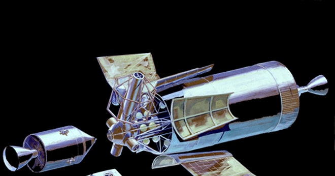
Philip Bono and Gerard O'Neill had refined their concept for ten years: since the days of LASS - Lunar Application of a Spent S-IVB. They had now a very detailed concept they were pushing for a post- Apollo 19 renewed lunar program.
Alas, NASA had shifted to a low Earth space station. Not discouraged, O'Neill and Bono simply moved the date to the late 1980's.
NASA LUNAR SHUTTLE. It consists, first, of an S-IVB stage upgraded with a XLR-129 engine. At the front of the stage is the Saturn Launch Adapter - SLA - with an Apollo Command Module bolted to it. The whole thing is a makeshift lunar shuttle. It is orbited by Saturn V lower two stages, upgraded: the S-IC with F-1As and the S-II with XLR-129s. Together they can lift a fully-fueled S-IVB: all 260 000 pounds of it; plus its 20 000 pound payload of a) the Command Module b) the SLA and c) wet workshop systems.
The upgraded S-IVB can now assume, first, a 3150 m/s TLI; followed by a 2400 m/s lunar descent... and later, injection of the Command Module to a 2700 m/s lunar escape trajectory: to a direct Earth reentry. The stage in that case burns during that reentry.
The Lunar Shuttle can also make a one-way trip with no Apollo and now crew. In that case, the SLA section is used to outfit the S-IVB behind it: as a wet workshop with enormous habitable volume.
This is very much a return of the old Direct Ascent flight profile of 1962: fifteen years ago.
According to Pr O'Neill "this is the most straightforward lunar architecture we could imagine, involving Apollo technology. It cuts the Lunar Module entirely; also the Service Module. The upgraded S-IVB assume all their missions, carrying a Command Module turned "cockpit". Instead of seven vehicles - three Saturn stages and four bits of Apollo - we only have four; three propulsive stages, storables, have been eliminated. Which should led to massive costs savings. This scheme could be our springboard toward a lunar return in the 1980's: as we could upgrade Saturn 517 for the new missions."
1978
Philip Bono and Gerard O'Neill had refined their concept for ten years: since the days of LASS - Lunar Application of a Spent S-IVB. They had now a very detailed concept they were pushing for a post- Apollo 19 renewed lunar program.
Alas, NASA had shifted to a low Earth space station. Not discouraged, O'Neill and Bono simply moved the date to the late 1980's.
NASA LUNAR SHUTTLE. It consists, first, of an S-IVB stage upgraded with a XLR-129 engine. At the front of the stage is the Saturn Launch Adapter - SLA - with an Apollo Command Module bolted to it. The whole thing is a makeshift lunar shuttle. It is orbited by Saturn V lower two stages, upgraded: the S-IC with F-1As and the S-II with XLR-129s. Together they can lift a fully-fueled S-IVB: all 260 000 pounds of it; plus its 20 000 pound payload of a) the Command Module b) the SLA and c) wet workshop systems.
The upgraded S-IVB can now assume, first, a 3150 m/s TLI; followed by a 2400 m/s lunar descent... and later, injection of the Command Module to a 2700 m/s lunar escape trajectory: to a direct Earth reentry. The stage in that case burns during that reentry.
The Lunar Shuttle can also make a one-way trip with no Apollo and now crew. In that case, the SLA section is used to outfit the S-IVB behind it: as a wet workshop with enormous habitable volume.
This is very much a return of the old Direct Ascent flight profile of 1962: fifteen years ago.
According to Pr O'Neill "this is the most straightforward lunar architecture we could imagine, involving Apollo technology. It cuts the Lunar Module entirely; also the Service Module. The upgraded S-IVB assume all their missions, carrying a Command Module turned "cockpit". Instead of seven vehicles - three Saturn stages and four bits of Apollo - we only have four; three propulsive stages, storables, have been eliminated. Which should led to massive costs savings. This scheme could be our springboard toward a lunar return in the 1980's: as we could upgrade Saturn 517 for the new missions."
December 1973
US ARMY CORPS OF ENGINEERS - NASA
THE SNAP-50 PORTABLE REACTOR AND THE ENERGY CRISIS.
SNAP-50 started as the Aircraft Nuclear Program: indirect cycle reactor. With ANP cancellation in 1961 it was taken over by NASA and the Army as a versatile, portable energy source: for Earth, space, Moon and Mars applications. The versatile reactor is space-hardened and could be the centerpiece of many solutions to the energy crisis; even more if plugged to a water hydrolysis plant and an ammonia manufacturing unit.
-Nuclear aircraft. This is due to its indirect cycle ANP legacy.
-Hydrogen aircraft: as studied in the Mobile Energy Depot.
-Ammonia aircraft: also from the Mobile Energy Depot studies.
-Synthetic fuels for ground and sea transportation: hydrogen, ammonia and methanol.
-Mobile nuclear power: being space-hardened, the safety factor is very high.
Spaceborne applications of SNAP-50 are: space stations Liberty and Destiny; future lunar bases; and Nuclear Electric Propulsion missions to comets Encke and Halley. Where the reactor provides electrical power to ammonia-fuel arcjets.
https://www.gm-volt.com/threads/alt...on-the-appletv-series-for-all-mankind.339920/
https://jalopnik.com/theres-a-very-plausible-alternate-history-1980s-electri-1846325454
OF BEACHHEADS, ENERGY DEPOTS, AND LUNAR BASES.
NASA / ARMY / NAVY OVERLAPPING REQUIREMENTS
A- NASA SPACE BASES AND LUNAR BASES
In September of 1963, Westinghouse Astronuclear was awarded a six month contract from the U. S. Army Corps of Engineers to perform an engineering study of both chemical and nuclear systems for lunar base power supplies. This report is written to show the extent to which the current SNAP-50/SPUR powerplant development program is directly applicable to the LUBAR nuclear powerplant concept recommended by Westinghouse Astronuclear in the interim report of the Lunar Base Study. The general ground rules for the nuclear portion of this study, as set forth in the request for proposal, were:
1. Initially an average power demand of under 100 Kwe with growth to approximately 1 Mwe.
2. Target date for launch to the moon of 1972.
3. Powerplant and necessary support equipment must be transportable to the moon using a single Saturn
The lunar base study is divided into two phases. The first phase is to survey the status of existing technologies and to recommend a most applicable concept. The second phase is to perform extensive studies based on the recommended concept of developing the powerplant, delivering, starting, and operating the powerplant on the lunar surface. The first phase has been completed and an interim report (WANL-PR(S)-004, Volume I and Volume II, Parts 1, 2, and 3) issued.
An initial concept, designated as LUBAR I (Lunar Base Reactor), was recommended in the interim
report to be followed by LUBAR II, later generation system of the same concept but with higher oper ating temperatures .
From a comparison of the LUBAR systems with the SNAP-50/SPUR system, the similarity of the technologies is readily apparent. This similarity is especially evident in the following sections through a description of the components for both concepts and a discussion of the component development program in progress for the SNAP-50/SPUR powerplant. The program which would be required to develop the LUBAR powerplant would be nearly identical to that in progress to develop the SNAP-50/SPUR powerplant. The major exception would be the main heat rejection system which in the lunar base application could utilize lunar gravity to provide natural circulation of the radiator fluid.
In general, it is concluded that the LUBAR concept represents the lower temperature range of the SNAP-50/SPUR technology. However, as growth capabilities of this system to higher operating temperatures are realized, the operating conditions of the lunar base systems would be expected to become nearly identical to those of the SNAP-50/SPUR powerplant.
DISCUSSION
1-Similarity of Requirements for Space and Lunar Base Powerplants
The general requirements for a space powerplant and a lunar base powerplant are similar. The power output for both systems ranges from less than 100 Kwe to about 1 Mwe and for lifetimes of at least one year. Specific weight must be minimized and the system reliability must be high for both applications. The environment of space is that of hard vacuum, meteoroids, and zero gravity. The environment of the lunar surface does, however, differ from space by having a lunar gravitational force approximately 1/6 that at the earth's surface.
The mode of heat rejection is by thermal radiation for both applications, however, in the lunar environment, the effective sink temperature is altered due to reflection and radiation from the lunar surface. At the operating temperatures of the main and auxiliary radiators, this higher sink temperature is not a serious concern. However, cooling of solid-state electronic devices to the vicinity of 150F is a serious problem on the lunar surface during the daylight periods and requires more elaborate systems.
Shielding is provided on the unmanned space powerplant to protect the electronic components of system. However, in the lunar base application, sufficient shielding must be provided to protect personnel against nuclear radiation from the reactor system. Due to the extreme cost associated with delivering a payload to the lunar surface, the utilization of lunar material is highly attractive. However, for the early application, the site preparation equipment and manpower required to move
this material into a shielding configuration would be prohibitive. For the earlier low power systems,
it does appear that sufficient shielding can be carried along with the powerplant without exceeding the capabilities of Saturn V booster.
2-SNAP-50/SPUR Development Program
The objective of the SNAP-50/SPUR development program is to provide a powerplant which produces a net electrical power output of 300 Kwe with an unshielded specific weight of approximately 20 lbs/ Kwe and a lifetime of 10, 000 hours. A powerplant of this type is adaptable to a variety of space missions such as electric propulsion, military applications, communications, and lunar base or space station power supplies. This program is currently in the design and component development phase. Design studies of all major components are in progress. A large number of materials tests have been completed and additional tests are continuing. Programs for the development of subcomponents have been initiated. In support of the reactor design, an extensive fuel irradiation program is in progress. Upon completion of subcomponent tests and component designs, testing of individual components, subsystems, and the complete powerplant will be performed.
Major milestone objectives of the SNAP-50/SPUR program include the reactor and non-nuclear powerplant tests. The SNAP-50/SPUR Project Office has recently established that the target dates for the start of both of these tests will be mid-calender year 1969 .
The development program for a lunar base nuclear electric powerplant, of the type recommended in the Westinghouse Astronuclear Interim Report, would roughly parallel that of the SNAP-50/SPUR development program. Over-all powerplant component tests for both systems would be expected to have the same general objectives, encounter similar problems, and require comparable facilities.
B- US NAVY - FACT SHEET ON BEACHHEAD OPERATIONS
TYPICAL CRITERIA
NUCLEAR POWER - BEACHHEAD PLANT
Title — Beachhead Plant, 100 KWE
Proposed Use — There are requirements within the Navy for portable nuclear power plants with electric power outputs of approximately 100 kw. Examples of military operations requiring a power source without dependence on continuous fuel or cooling water supply are: support of beachhead operations and tactical missile systems, air head operations including field hospitals, remote locations. Their requirements are very similar to the Army Mobile Energy Depot own portable nuclear reactor - the MCR: military compact reactor.
1. The power plant will reject heat to the surroundings by means of an air-cooled heat exchanger.
2. Beachhead, landing and tactical operations will be completed within three days. Base development will be initiated after the first day of beachhead operation. Base development will be a continuous effort for 30 to 60 days.
3. Requirements for power plants during tactical operations include dispersion, quietness of operation, portability (trailer or truck-mounted) and ship-to-shore delivery systems for fossil fuel.
4. Power plant size will be limited to 100-kwe output. Power plant weight will not exceed 2500 pounds.
5. Tactical airfields, maintenance facilities and conmunicatlons systems represent the major power demand for the beachhead power plant. All equipment utilized in these facilities requires a high degree of portability.
6. Total electric power requirements for services during beachhead operations are of the order of 1000 kw.
7. During combat operations, power supplies are required to have a high degree of reliability. Reliance on a single power source is difficult to justify and a multiplicity of units is indicated.
8. Transportability during beachhead operations is limited by the lifting capacity of helicopters. Helicopters for beachhead operations are capable of carrying 2500 pounds. Five-ton trucks represent the upper limit of ground-vehicle load-carrying capability.
9. Electric power is also required for hospitals, lighting, refrigeration and water purification during initial beachhead operation.
10. Approximately 10 days after beachhead establishment, base development and electric power demand will Justify the utilization of a larger power plant such as the advanced base plant. The stringing of transmission wire for load distribution will be feasible at that time.
The object of the current Systems for Nuclear Auxiliary Power (SNAP) program is to develop power plants with weights of 10 lb per kwe, including reactor, power conversion unit, radiator and any necessary shielding. Usually the shielding considered for these space power plants consists of just enough material to protect sensitive equipment in proximity to the reactor from radiation damage. If it is desired to provide shielding on the beachhead plant reactor, adequate to allow personnel access to the plant after reactor shutdown, the total weight of the unit will be substantially greater than that of 'a similar unit used unshielded for space power.
The power conversion system must match the reactor in compactness and light weight. At the present time, three systems show promise for this application. All are under development but none is ready yet for efficient practical application.
The heat rejection requirements of the beachhead plant are somewhat less stringent than those of a comparable space power unit. The latter can reject heat only by radiation in the space vacuum. For beachhead operations, heat rejection will, in general, be to air or ground to enhance the plant mobility and render the plant independent of a water supply.
The space reactors will become lighter and more compact as they develop, from SNAP-2 to SNAP-8, to the ORNL Intermediate Reactor, to SNAP-50 and the thermionic reactor. At what point these power plants will become small enough for beachhead plant applications is not immediately apparent.
The selection of a power plant for beachhead operations depends on the following:
a. Advancement of the technology of nuclear fuels, reactor control, efficient power conversion systems, materials, etc.
b. The development of a nuclear reactor system, including reactor and power conversion system, capable of 100-kwe output, which weighs 25-50 pounds per kwe or less, including appropriate shielding and which does not require highly trained personnel or setup time in the field.
c. The development of a military requirement for such a plant in beachhead operations which will justify the replacement of diesels.
It is concluded that:
a. There is no nuclear power plant that will be available in time to meet the original schedule stipulated for this plant in the Scope of Work statement.
b. There is a good chance that such a plant will become available within the next 20 years, due to the space nuclear power development effort.
C- THE ARMY MOBILE ENERGY DEPOT
Army attention was initially directed toward the use of a SNAP-50/SPUR type reactor as an advanced Mobile Compact Reactor for the Mobile Energy Depot. Since the reactor power levels required for both SNAP-50/SPUR and the MCR are in the same range, both applications required high temperature liquid metal coolants to achieve light weights, and both applications used fast spectrum reactors.
The high temperatures attainable with a SNAP-50/SPUR type reactor, as compared with those of the present MCR powerplant, could make possible higher power outputs and efficiencies. In reviewing MCR requirements it became apparent that an attractive alternative which could be realized much sooner would be the use of the LCRE reactor, coupled with an engine already developed to achieve the goals of the present LCRE program. This reactor could be run at reduced temperature to supply heat to the Pratt & Whitney Aircraft FT-12 free turbine engine, using a liquid metal-to-air heat exchanger of the type developed by Pratt & Whitney Aircraft in the Aircraft Nuclear Propulsion Program.
The proposed powerplant consists of a lithium-cooled reactor, identical to that to be used in the Lithium-Cooled Reactor Experiment (LCRE), which was scheduled for test in late 1965, and the Pratt & Whitney Aircraft FT-12 engine, a marine development of the JT-12 engine. This engine employs the open Brayton (gas turbine) cycle with a liquid metal-to-air heat exchanger replacing the usual burner. A generator, driven by the gas turbine, provides a net electrical output of 2250 Kw of 3-phase, 60-cycle current. Overall weight of the proposed powerplant, including shielding is estimated to be 125,000 pounds.
This approach to the Mobile Compact Reactor Program has tremendous appeal, since it makes use of both a reactor which was being designed as part of the SNAP-50/SPUR program and of an existing FT-12 engine used to power the Sikorsky Sky Crane helicopter (currently being constructed for the U.S. Army) and which is also under development for a Naval application.
Other components, such as EM pumps, are state-of-the-art. The only additional development program required would be that needed to marry the components into an integrated system.
COMPLIANCE WITH DESIGN OBJECTIVES OF THE MILITARY COMPACT REACTOR
The following compares the LCRE mobile plant characteristics with a condensed version of the requirements:
1. Requirement
The powerplant must be in one, self-sufficient package, including shielding, with the exception of an internal control module. It must be capable of startup, shutdown, control, and monitoring without recourse to external power sources.
Comment - The powerplant includes a self-contained auxiliary power unit for startup and shutdown power. It has a self-contained shield which reduces radiation doses to 10 mr/hr or less, outside a 450-foot radius.
2. Requirement
Maximum protection against small arms fire and against the effects of large bursts of neutron and gamma rays are to be provided.
Comment - The reactor and primary loop are protected from small arms fire by their radiation shielding. The turbine engine and generator are believed to be invulnerable. Circuit breakers and other switchgear will be protected by local armor plate. The thickness of secondary piping and tankage will be chosen to resist small arms fire damage.
To avoid damage from radiation bursts, the control system will be designed without radiation-sensitive solid state devices and, if possible, vacuum tube amplifiers will be replaced by magnetic amplifiers or similar devices. If appropriate, radiation-sensitive switches will be provided for momentarily shutting off critical circuits.
3. Requirement
The minimum power level is to be 2 Mwe net
4. Requirement
The powerplant weight should allow disassembly into packages for air shipment, none of which should exceed 40500 pounds. The maximum dimensions of any package should permit shipment on C-124 and C-133 aircraft. The powerplant should be carried on a standard military trailer as an integral unit. In March, 1963, it was recommended that the transportation requirements be relaxed to require the use of one trailer only on paved highways.
Comment - Studies of the best method of packaging for air shipment are still in progress, but the heaviest and largest package undoubtedly will include the reactor, inner gamma shield, primary liquid metal loop and secondary liquid metal loop (including the liquid metal-to-air exchanger). The weights of these components are estimated to be 25, 000 pounds. It would be necessary to rearrange or augment the shielding to obtain adequate protection during shipping, raising the weight of the package to about 35, 000 pounds . The maximum dimensions of the package are 8 feet, 6 inches in height and 20 feet in length, both with in the allowable load dimensions. The powerplant was laid out to fit the XM524 military trailer specification. Recent communication indicates that the Army will not purchase trailers to this specification but will purchase commercial trailers of like capacity for the XM524 requirement. The Fruehauf model CD-120WD-16 drop-deck trailer appears to have the desired capacity and size for the powerplant on paved highways.
5. Requirement
The powerplant should be transportable by rail, ship, overland, and by C-124 and C-133 aircraft, taking due account of the shock-loading encountered.
Comment - The package sizes suitable for aircraft can readily be loaded into ships, railroad cars, or semi-trailers. The LCRE was designed for 2-g loading and will require reinforcement at the juncture of the reflector outer container with a mounting skirt, in order to survive the 15-g shock condition associated with rail transporation. The reinforcement can be applied in the form of external doubler plates. The use of a shock-absorbing material between the reactor mounting and the skids would also ease the problem. Other components are de signed for rail, ship and air transportation and do not require modification.
6. Requirement
The powerplant should be capable of operating without appreciable loss of power on a 60 percent fore and aft slope and a 30 percent lateral slope.
Comment - The liquid metal circuits employ EM pumps not requiring control of liquid metal level or attitude. Therefore, the liquid metal loops will operate at the slopes specified. The en gine will present no problem, since it is designed for aircraft attitudes and accelerations. The generator will be furnished with a thrust bearing, making it capable of operating at the 60 percent fore and aft attitude .
7. Requirement
The basic powerplant life should be 50, 000 hours; the interval between major overhauls should be 10, 000 hours, and the reactor core life should be 5000 full power hours.
Comment - As discussed in detail in the Appendix, available information on 1500F liquid metal systems contained by iron or nickel base alloys indicates that measurable mass transfer occurs in 1000 hours. The prospects are poor that this system, or any other using the same materials and temperatures, would survive 50, 000 hours. A realistic goal is 10, 000 hours. The period between major overhauls would probably be determined by the engine. GG-12 engines (the gas generator section of the FT-12) are being developed for approximately this period between overhauls and one such engine has operated for most of this time period without overhaul. The reactor core is capable of operating for 7500 full power hours.
8. Requirement
The system should be capable of a transition from shutdown to full power in 30 minutes and a transition from full power to readable shutdown (all fluids left in place) in 15 minutes.
Comment - The shutdown requirement poses no problem, because the primary loop containment material has a high thermal diffusivity combined with a low Young’s modulus and low coefficient of thermal expansion. Even a scram does not result in severe thermal stresses and rapid shutdowns are feasible. Most of the time would be taken up by transferring electrical load to the APU and reeling in cable. The time required to transfer load could be virtually eliminated by allowing the APU generator to float on the line as a synchronous condenser and by causing the APU to start automatically to maintain APU generator speed. Assuming the startup to occur with liquid metal coolants in place, the startup time would be determined by the safe reactor period. Assuming reactor startup time to be the same as in similar aircraft propulsion systems studied in the past, a 30 minute startup time is possible.
CONCLUSION
A portable reactor derived from the SNAP-50 could be useful, altogether: to Navy beachhead operations; to the Army mobile energy depot; and to a NASA space station and lunar base. Other applications might be a reborn nuclear aircraft with modified JT-12 engines; a nuclear electric lunar freighter and robotic probe.
October 1967
"First: Lunar Exploration Systems for Apollo - LESA - and its vast shelter. Next: Lunar Applications of a Spent S-IVB stage - imagine a wet workshop landed on the Moon. And finally: the Space Launcher Adapter: short, SLA.
It is my opinion that a combination of the three - LASS, LESA and SLA - if combined with the Marius Hills Hole could led to a rather formidable lunar base." Scientist-astronaut Gerald K. O'Neill.
Scott Kenny
ACCESS: USAP
- Joined
- 15 May 2023
- Messages
- 11,628
- Reaction score
- 14,305
Fun question would be what the lunar bulldozer would look like. I mean, you need to shove all that regolith around somehow, or else you can't use it for radiation shielding!
Unless you drop it at the bottom of a hole, freely dug my Mother Nature 1 billion years ago. Talking about it...
1970
...
To date, 25.42% of the Moon has been imaged by the PERSEUS orbiters. So far we have found more than 150 small - average diameter 15m - pits in impact melt deposits of Copernican craters.
More recently we found two new large mare pits, similar to the three pits discovered in Kaguya images. One is in Schlüter crater, a mare-filled crater near Orientale basin, with a 20 x 40m opening, approximately 60 m deep. The second new pit is in Lacus Mortis, 44.96°N, 25.61°E; in a tectonically complex region west of Burg crater. This pit is the largest mare pit found to date, with an opening approximately 100 x 150 m, and a floor more than 90 m below the surrounding terrain. Most interesting from an exploration point of view is the fact that the east wall appears to have collapsed, leaving a relatively smooth ~22° slope from the surrounding mare down to the pit floor.
...
The existence of sublunarean voids was hypothesized as far back as 1885 (e.g., Nasmyth and Carpenter, 1885, Coggins and Pratt, 1952, Halliday, 1966, Heacock et al., 1966, Hatheway and Herring, 1970).The first-discovered pit is located in the Marius Hills region of Oceanus Procellarum (14.1°N, 303.2°E). The two other pits were found within Mare Tranquillitatis (8.3°N, 33.2°E) and Mare Ingenii (36.0°S, 166.1°E).
...
The first three 60–100 m diameter mare pits were first identified in 10 m pixel scale images and were proposed to have formed as active lava tube collapses, sometimes known as skylights. Later 1 m pixel scale observations revealed that at least two of these pits provide openings into subsurface voids of unknown lateral extent. These discoveries led to an initiative to search for additional pits identifiable in meter-scale images.
This search revealed 228 previously unknown pits with diameters ranging from 5 m to 900 m, and a median pit diameter of 16 m. The majority of these newly discovered pits are located in impact melt deposits, though five of the new pits are found in mare materials outside of impact melt deposits. Additionally, two pits are located in non-impact-melt highland materials.
...
To date, we have identified ~281 pits in melt deposits of impact craters, 15 pits in mare basalts, and 5 pits in non-impact-melt highland terrain.
...
We have now identified almost 300 pits, mostly in ponds of cooled impact melt inside large craters younger than ∼1 billion years. Several of these pits may provide access to lava tubes or other caves, and those in the maria expose the layering record of the top 20–100 m of basaltic lava flows. We also have investigated the 21 known pits outside of impact melt ponds to determine possible origins, ages, and present‐day access to the lunar subsurface. Lunar pits provide cross-section exposures up to 100 m thick through their host terrains, and perhaps even enable access to subsurface void spaces that could provide shelter for future explorers.
...
Of all the mare pits, only the Marius Hills pit lies within a sinuous depression. The strongest indicator of a potential lava tube related to a pit is linear collapse feature crossing a wrinkle ridge, aligned with the West Marius Hills pit (45 km from Marius Hills pit). This evidence suggests that the West Marius Hills - and perhaps Marius Hills - pits may have collapsed into lava tubes.
These lunar pits are nearly 80 m deep and 80–100 m in diameter. The temperature is expected to be a balmy - 25 °C compared to surface temperatures reaching 130 °C during the daytime and up to −150 °C in the night-time: a whopping 280 °C shift.
Just to be precise: all the stuff above comes from science papers published since 2009, when Kaguya stumbled on the Marius Hills Hole.
I hadn't checked the news for a few months, and - wow.
300 pits.
Just think about it.
Three-hundred.
The sky(light) is no longer the limit.
I hadn't checked the news for a few months, and - wow.
300 pits.
Just think about it.
Three-hundred.
The sky(light) is no longer the limit.
You hang a reactor (with lead shields piecemeal added like Chobham armor) half-over the blade so you can bear down.Fun question would be what the lunar bulldozer would look like. I mean, you need to shove all that regolith around somehow, or else you can't use it for radiation shielding!
Mass is your friend here.
Once done, just park it and connect cables to other regolith-movers. The dozer is now a mobile power plant.
I’d really like it in a nitrogen filled lunar lava cave. Oxygen only for suits.
Once you have an inner airlock, then you use it in the vacuum at end of service life.
Last edited:
And here's another one that blew my mind even further. The two Marius Hills Holes, 45 km apart, could very well be connected by an underground lava tube / cave of mind blowing size.
This suggests
the presence of a potential lava tube, which is confirmed by the results of the forward method and lunar radar
echo data.
The extent of the lava tube is estimated with the forward method to be ~60 km in length, ~9 km in width, ~605 m in depth, and ~55 m in height.
"9 km in width" - sounds exagerated ? not so much. I have similar papers somewhere, saying lunar basalt, as sampled by Apollo; with a roof thickness of 500 m or more; could support kilometer-wide caves. Hail lunar gravity only 1/6th of Earth.
Scott Kenny
ACCESS: USAP
- Joined
- 15 May 2023
- Messages
- 11,628
- Reaction score
- 14,305
9km wide but only ~55m tall seems an odd shape for a lava tube, most lava tubes on Earth are round or closer to a 2:1 width:height. (I live in a place with lots and lots of lava tubes to explore) Must be that Lunar Gravity!
Yep.
But you really want the ends at least to be pinched….so you can block them more easily. Maybe inflate a dome inside that you can project a “blue sky” on for peace of mind.
Unless you’re a Goth and like the Dante’s Inferno look.
For your Hollow Earth—you have to go to the Moon as it were.
Fill with air and light…how tall might Redwoods grow in lesser gravity?
I imagine if you could clone a T-Rex in the manner of Jurassic Park…it could grow to be Godzilla size up there. Gene spliced dragons could fly…
Washington state and Oregon ? (just asking in passing)(I live in a place with lots and lots of lava tubes to explore)
Something interesting facts about lunar pits / skylights / lava tubes.
Those 300 holes might be "competitors" to the better known lunar cold traps (Shackleton crater !). At latitudes below 75 degrees.
Indeed the bottom of the pits could very much traps volatiles and keep water ice away from sublimation.
Some numbers about cometary impacts: they could deliver a few million tons of water ice to the Moon once every 30 million years.
Basically a 1-km size comet weights 1 billion tons, but after the impact less than 10%, if not 1%, of the water is retained by the Moon. That's 10 million tons of water now looking for a place to go in a hurry: before the harsh temperatures of the lunar day sublimate the water.
That water now has two options to get trapped on the Moon.
Option 1 : migrate to the polar cold traps at latitudes above 75 degrees
Option 2 : find a (closer) lunar pit / skylight and fall to the bottom and from there, to lava tubes. Remember, there are 300 pits like that.
It's pretty fascinating...
Last edited:
Gene Shoemaker was having the thrill of a lifetime.
"Preliminary result from Apollo 15 mission to the Marius Hills are just jaw-dropping.
So on one hand, we have all those pits found by PERSEUS imagery. And on the other, we have extensive seismic studies of Procellarum: by Ranger, Agena and Apollo seismometers; ringed by Lunar Orbiter, Agena, S-IVB and Lunar Module crashes. They have unmasked enormous underground voids: that might be lava tubes of epic size.
"All right, now it is time to bring together the voids and the pits: since the pits could led to the voids, that is: lava tubes. And the combination of the two could be an extensive cave network stretching across the Ocean of Storms underground. That would be a very significative discovery: imagine the exploration, the lunar base and the lunar colony inside the cave network.
"So - first map: the pits.
We have multiple pits at Aristarchus and Kepler. Also the Marius Hills: two of them, 45 km apart. They might be connected by a gargantuan underground lava tube, 60 km long and 9 km wide.
"And this bring us to the voids found through seismic data. Second map, south to north: Cavalerius, Rima Galilaei, Marius Hills, Rima Marius, Aristarchus, Kepler, Wollaston, Shroter, Mairan, Rumker.
The voids locations stretch from 8 degrees north (Cavalerius) to 36 degrees (Wollaston, Mairan). On the Moon, 1 degree is 31 km because of a 11000 km equator divided by 360 degrees. And thus, 24 degrees would be 700 km, north to south. As for East to West: most of the voids are located between 302 and 314 degrees: 12 degrees, 31 km: that's 370 km.
"So we have a broad area of Oceanus Procellarum, a rectangle 700 per 300 km, that concentrates truly gigantic voids: indeed they are 60 km to 180 km in length ! Hence the length of the voids - potential lava tubes - is the same order of magnitude as their geographical perimeter.
"In simple english: we have nine potential giant lava tubes packed into the same broad corner of the Moon; with a few access pits on top of them: Marius has two, but Aristarchus has a many more.
"Aristarchus: let's talk about that one. One of the weirdest places on the Moon. Nothing is ordinary there: the gravity, the moonquakes, the infrared spectrum, the optical landmarks... the pits and the underground voids... and the LTE: Lunar Transient Phenomenas. Aristarchus seemingly concentrates all the bizarre Moon features we have indentified over the last decades. By this metric, colossal lava tubes underneath would be almost a non-surprise.
"And now, let's throw the Reiner Gamma anomaly into the mix.
"We start from Cavalerius, which has a few big voids. From there, it is a short hop to Reiner Gamma. North of the anomaly, we have a whole bunch of pits and voids: Rima Galilaei, Marius Hills, Rima Marius. Then if we keep going North, were do we go ? Direction West, nearby Kepler has its own lot of pits, but we go North. Well, next step is Aristarchus, then Wollaston, and finally: the Shroter Rumker - Mairan area, with even more voids of colossal size.
"So a good case can be make that the voids and a few pits on top of them, are heavily concentrated, first in the Reiner - Galileai - Marius broad area; and then around Aristarchus.
"We don't know if they are connected but if they were, the resulting network would be as long as Mammoth Cave, New Mexico: the longest cave system on planet Earth, 400 miles so far and the end is still not in sight, after decades of exploration.
"Finally, this bring a truly fascinating hypothesis. If Reiner Gamma is the scar of a big cometary impact a few million years ago; the said impact might have send cometary water all around the pits and underground voids we mentionned. Just think about it: cometary water flying from above and landing in the Marius, Kepler, and Aristarchus pits. And, even more fascinating: cometary water burying itself in the lunar crust... and finding that extensive cave network along the way. It might be still there, trapped frozen.
"Put together, that makes the Ocean of Storms a rather exciting place. Apollo 15 did a stupendous job, but they might have just scratched the surface.
martinbayer
ACCESS: Top Secret
- Joined
- 6 January 2009
- Messages
- 3,397
- Reaction score
- 3,904
Somehow First Men in the Moon comes to mind...
Somehow First Men in the Moon comes to mind...
Which one ? book or movie ?
Scott Kenny
ACCESS: USAP
- Joined
- 15 May 2023
- Messages
- 11,628
- Reaction score
- 14,305
Pretty close, I'm in Idaho. Craters of the Moon national monument is about 2 hours away.Washington state and Oregon ? (just asking in passing)
martinbayer
ACCESS: Top Secret
- Joined
- 6 January 2009
- Messages
- 3,397
- Reaction score
- 3,904
Movie - don't know (or care) how much that might differ from the book.Which one ? book or movie ?
Last edited:
DEVELOPMENTS IN TECHNICAL CAPABILITIES FOR DETECTING AND IDENTIFYING NUCLEAR WEAPONS TESTS
FRIDAY, MARCH 8, 1963
"Yesterday we concluded that portion of the hearing pertaining to detection of nuclear explosions underground and underwater. We now move into the problem of detecting high altitude nuclear tests. We will be concerned with two aspects of this problem, the first having to do with the ground-based detection program, and the second relating to the satellite-based detection program.
STATEMENT OF DR. ALOIS W. SCHARDT
DEPUTY DIRECTOR, NUCLEAR TEST DETECTION OFFICE, ARPA.
Mr. Chairman and members of the committee:
The problem of detecting nuclear tests conducted above 30 kilometers and out to 300 million kilometers from the earth was studied intensively in 1958 and 1959. Most of the findings were summarized in the recommendations of the Technical Working Group I which met in Geneva in July of 1959.
At the same time the AEC laboratories initiated the development of ground-based optical sensors for detecting visible light and satellite-based sensors for X-rays, gamma rays, and neutrons. On September 2, 1959, the overall responsibility was assigned to ARPA for establishing a research and development. program to improve our capability to detect nuclear detonations conducted underground or in space.
The high altitude portion was divided into two parts, one oriented to ground-base instrumentation and the other to satellite-based instrumentation.
Satellite-based detection: It was recognized from the outset that a satellite system would have a greater detection range than a ground-based system. However, at that time it was barely 2 years since the first satellite had been launched and the technology did not exist for fabricating reliable spacecraft of the required complexity.
A joint Air Force/AEC/NASA working group was established to formulate an R. & D. program in this field. In the meantime, work continued in the AEC laboratories on the development of suitable detectors under both DOD and AEC sponsorship.
The recommendations considered four types of satellite systems: Argus, near-earth, far-earth, and solar. The joint working group decided that the research effort should be concentrated on the far -earth system with satellites well beyond the Van Allen radiation belts.
The presence of the radiation belts restricts severely the orbits of the near-earth system. Since the earth cuts off practically one-half of the field of view of a low altitude satellite, one has to be sure that thesatellites are properly distributed around their orbits.
On the other hand, the earth obscures less than one-tenth of 1 percent of the field of view of a far-earth satellite. This means that the satellites do not have to be positioned accurately with respect to each other.
By 1961, space technology had advanced to the point where a meaning R. & D. satellite program could be defined and an initial five-launch program was approved in June of that year. This programwill reach fruition during the next year since the launches are scheduled to commence in the second half of 1963.
During this period, the near-earth background was investigated by payloads flown piggyback on scheduled DOD vehicles. In the fall of 1961, instruments designed and built by the Lawrence Radiation Laboratory at Livermore pre flown successfully in polar orbits.
On the basis of these and other experiments, we are now in a position to define the orbit parameters for a near-earth system.
The ground-based detection techniques are proving capable of reliably detecting tests conducted in earth/moon space, and coverage by satellites near the earth is not essential. Thus the satellite system could cover primarily deep space, and fewer than six far-earth satellites would be required because the geometric constraints are less severe.
The following assessment may be made of the relative roles of ground-based and satellite-based detection. The ground-based system can be implemented rapidly since most of the basic instrument development has been completed.
Even if restricted to locations outside the Communist bloc countries, it will have the capability to detect a 10 kt unshielded test roughly out to earth-moon distances.
In a general discussion like this it is pointless to specify the detection range more accurately because this ran is a function of test location and conditions as well as of the background conditions which prevail at the time of the test. Later in this paper I will discuss specifically some of the circumstances which make detection more difficult.
Initially, the satellite-based system will have as its primary function the detection of deep space tests, with an eventual range of 300 million km for an unshield 10 kt test.
As technology improves, the time may come when it will be more economical to cover also the earth-moon space with satellite-based detectors rather than with a worldwide system of ground stations. However, at this time, there are still a great many unknowns about the operation of satellite systems which will not be resolved until flight experience has been obtained. Therefore, during the next 2 or 3 years our primary reliance will be on the ground-based systems.
Shielding. In the above discussions we have been concerned primarily with tests which are conducted without any attempt to frustrate the detection system. Work at Lawrence Radiation Laboratory and the Rand Corp. has indicated that it is possible to shield against the radiations emitted by the detonations.
Analysis of radiation emitted by shielded tests in turn has led to the conclusion that, at least for the satellite detection system, much of the detection capability can be retained by using different sensors than those designed for unshielded tests.
The picture emerges therefore that detection measures and countermeasures can be devised in such a way that one side could gain a distinct advantage if development effort on the other side is discontinued.
Primary emphasis in the theoretical work has been on shielding against the X-rays because these are subject to the greatest detection ranges and at the same time are more easily shielded than the gamma rays or neutrons. With the so-called thin shield which was described to this committee in previous hearings, the X-ray flux can be attenuated by a factor of 100 to 1,000 and the radiating temperature can be reduced from 1 to 5 kilo electron volts to about 100 electron volts.
More elaborate shields have been designed for even greater attenuation factors. However, these designs need experimental verification because it is always possible that some process was overlooked which permits a small fraction of the energy to penetrate the shield.
The scientists at the AEC’s Lawrence Radiation Laboratory have been exploring the possibility of conducting the experiments to determine shielding effectiveness. Unfortunately, rather elaborate nuclear tests in space are required for this purpose.
It would be most desirable to obtain experimental evidence to put shielding calculations on a firm basis; therefore, we are exploring the possibility of conducting such tests. However, so far this is not a priority matter, because the development of sensors designed to detect shielded tests has not progressed to the point where more information is needed about the radiations emitted by a shielded test.
In addition to designing the shield, it has to be fabricated, boosted into space and deployed in the proper geometry at test time. These engineering problems are basically no different from the problems encountered in space exploration. The degree of sophistication and reliability that will be required for the successful completion of the manned lunar mission is judged to be more than adequate to conduct a test with rather elaborate shielding.
Already the Mariner II Venus mission has demonstrated many of the techniques needed for a successful completion of a shielded test. It is therefore clear that we have to develop the technology for detecting shielded tests.
Piggyback flights have been scheduled for a preprototype model. This work will give us a better understanding of the problems associated with the use of such a detector. Another attack on the shielding problem is the use of solar satellites. The primary problem in this case is communication over tens of millions of kilometers and this is being attacked by NASA in their planetary program.
Instead of, or in addition to, deploying an artificial shield, a violator could try to take advantage of natural situations. I would like to mention briefly two such special cases.
(a) Tests conducted behind the moon. Such tests could be detected with solar satellites. For large tests, earth satellites are expected to detect the delayed gamma-rays from the debris which expands beyond the moon's diameter.
(b) Tests conducted during solar flares. Most of the detection instruments, both ground and satellite based, are affected by solar activity and therefore it will be more difficult to detect and identify tests which occur during these periods. However the time of a solar flare occurrence cannot be predicted with any degree of certainty and a violator would be greatly handicapped if he tried to restrict himself to these periods.
In concluding my remarks on shielding I would like to emphasize that one cannot promise a foolproof detection system that covers the space within the earth’s orbit around the sun. However, a fully implemented system will greatly limit the freedom of the potential violator in conducting these tests and will increase his costs and, therefore, also the size of the operation and the number of people involved. This, in turn, produces an increasing-requirement in the level of security the violator has to maintain in his operation.
So I found that ARPA Congressional Hearing from 1963 and cleaned it up a bit. There are some pretty crazy stuff in it.
Bottom line: they considered the possibility of the Soviets detonating a planetary-probe-nuke as far as 300 million km. Can you believe that ?
This is farther than freakkin' Mars: actually at the treshold of the asteroid belt.
Also closer testing involving the Moon or... solar flares.
Sweet geez.
I of course will integrate that in my TL. Teller truly was a paranoid megalomaniac.
Time for a few lame jokes...
"If NASA ever create new space stations, post Liberty and Destiny: they'd better check their acronyms. America Space Station and Lunar Orbit Space Station would result in rather unfortunate acronyms... "
"If NASA ever create new space stations, post Liberty and Destiny: they'd better check their acronyms. America Space Station and Lunar Orbit Space Station would result in rather unfortunate acronyms... "
Last edited:
Scott Kenny
ACCESS: USAP
- Joined
- 15 May 2023
- Messages
- 11,628
- Reaction score
- 14,305
About like running a suggestion poll for the mission name for the Uranus probe...Time for a few lame jokes...
"If NASA ever create new space stations, post Liberty and Destiny: they'd better check their acronyms. America Space Station and Lunar Orbit Space Station would result in rather unfortunate accronyms... "
Similar threads
-
 NEXT Lunar Colonisation Program
- Started by Michel Van
- Replies: 9
-

-
Original US space program without the moon goal.
- Started by carmelo
- Replies: 4
-
Zond (and the Soviets) beat Apollo NEAR the Moon (not to the surface)
- Started by Archibald
- Replies: 14
-