Could a Ducted Rearplace Compression engine work?

malipa

TU Delft AE student
Joined
14 June 2012
Messages
189
Reaction score
10
It would work like this:
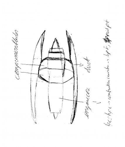
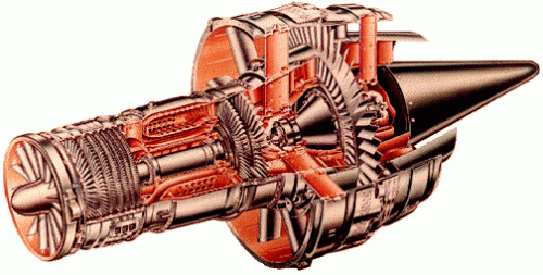
The entire engine will be ducted, it will look like an normal aircraft engine, except the duct will be longer at the end to make reverse thrust possible.
You have an engine core at the front, So: Intake -> Low-pressure compressor -> High-pressure compressor -> High-pressure turbine -> 2nd High pressure turbine (to drive the low pressure compressor, but it those this with less blades) -> The low(er)-pressure compressor (which drives the fan/compressor blades).

The fan/compressor-blades are ducted to make compression able, which, to my opinion, could give leaner combustion because:
- You will have a weight decrease
- The fan/compressor-blades can turn at their own most efficient rate.
- The core is only build to give high-pressure air, so it can be made smaller, lighter (you will miss the third (or in case of rolls royce fourth) axis), and totally specialized for the lean combustion.


What do you think?
 
I suppose it could work, but:
- you'd be running the duct at a really low compression ratio, making it inefficient.
- a bypass engine is efficient because the bypass air leaves the engine at a speed that matches well with the surrounding air. Increasing the speed of the bypass air will reduce the efficiency.
- you would be replacing the existing bypass engine with an engine that needs two sets of combustion chambers, and two exhaust turbines, so it gets a lot more complicated for the same power.
 
Actually the bypass air in a normal aircraft engine will be boosted. And the engine will only need one engine core, it is front placed, not rear placed.
 

Attachments

  • Concept 001.jpg
    Concept 001.jpg
    131.5 KB · Views: 211
I'm afraid you've lost me. Can you make a drawing of your idea?
 
Like Hobbes I'm not quite certain that I have fully understood your explanation, but to me it sounds vaguely like you might be re-inventing the aft-fan configuration? This, obviously, has been done before with some success:
http://www.f-16.net/attachments/cf700_aft-fan.gif
 
Weird, I'm not a member over there and the image works just fine for me if I simply click on the direct URL - in fact I got it from Google image search without ever opening the thread at f-16.net! I'll see if I can find a picture which is more easily accessed.
 
It certainly looks the same, but the difference lies in the dual blades, which have an ultra high bypass ratio, in the fact that the air is compressed and in the narrow design of the core that is shorter, lighter and more efficient.
 
Aren't we just describing the fan engine... there were front, mid and aft fan schemes investigated before the Rb 207 emerged. In fact Derby looked at 11 configurations in all. As we can see by all the Eurpean/American activity on next generation engines at the moment we can combine the component parts of a gas turbine in many ways but it is the physics of operating around the whole envelope that will kill many ideas as well as the matching of driver and driven parts.... and then there are leakage paths which allow efficiency to drain away.
The first pic is RRs E3E core engine demonstrator GA and this link takes you to the NEWAC concept for an 'innovative' core by the Swedish participants in the European programme.
I would still like to see a sketch.
 
Erm, isn't that just the GE-36 UDF (UnDucted Fan) in a duct? The final stage has to be a turbine as it extracts power to drive your rear-mounted fan blades - if its a compressor, what is driving it?
 
Actually the aircraft will fly on compressed air instead of the normal 'fanned' air. I think the energyloss will me lower comparing it with an turbofan aircraft. Lets call my engine an turboblade aircraft.
 
If you run on compressed air, you will use more energy compressing the air than you can ever recover. So this will be less efficient than a turbofan.
 

Similar threads

Back
Top Bottom