comic stuff

Justo Miranda

ACCESS: Above Top Secret
Senior Member
Joined
2 December 2007
Messages
6,718
Reaction score
8,426
Website
www.amazon.com
Hi,

I Have developed a reasonably accurate method to obtain 3-views scale drawings of the vehicles we can find in our favourite comics and films.
Its only purpose for now is just to have some fun as there is not a market for a specialised publication on the subject.
I hope it will be interesting for some modelers.
 

Attachments

  • Escanear.jpg
    Escanear.jpg
    442.6 KB · Views: 238
Justo,

How about some drawings of the F/A-37 Talon and UCAV from the movie, 'STEALTH'. Thanks.
 
here the offical home page of the Designer of F/A-37 Talon and UCAV

http://www.oliverscholl.com/

here the STEALTH'.stuff
http://oliverscholl.com/thumbnails.php?album=16
 
The method is very much handcrafted, although very simple, and based on a test/error/test mode.
Its effectiveness depends on practice and experience and, unfortunately, is not transferable. You could compare to the use of the sextant, if the sailor knows his profession he may be able to calculate his position to an error of 1000 meters.

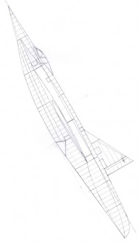
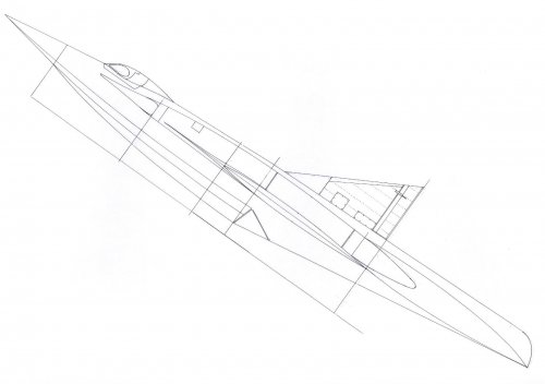
The process I usually follow is to draw the approximate profile over a cardboard, then cut it and compare it with the picture or drawing in the same angle. After that a tedious series of pencil marks and cuts follow until shadows, lens distortion and perspective effect are is cancelled.

Next step is to add details and paneling lines to learn about the airplane structure and identify the most probable position of the center of gravity and main wing spar.
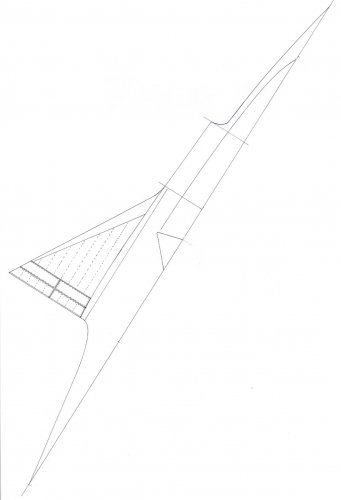
Then, practicing a cut at the wing root position, I introduce a rectangle of cardboard that I will cut and try and compare it with the picture, until obtaining a shape most similar to the wing (dihedral angle included).
Same procedure is repeated with the tailplane.
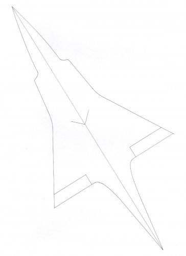
Disassembling the whole thing it is already possible to draw a very basic three view.

It usually is very useful to know the type of engine. If you have this piece of data, you may find out data on the airplane measurements and make an statistic adding up measure on the propellers diameter o air intakes, the size of the pilot head or the height of people and equipment that may appear around the airplane when landed.

Sometimes the diameter of the tyes is a known measure. I have tables with measures of just the Luftwaffe tyres.

Once you have the size, the initial three view is scaled up to the most convenient size and small copies of the pilots and engines, at the same scale, are positioned in the most probable places.
It is not possible to get very much wrong as the inner space always adjusts to these elements.
Same procedure is repeated with small copies of cannons and machine/guns. Some room must be reserved for the most probable position of ammunition containers.

Next step is to imagine the optimum inner structure able to keep all the elements together.
The remaining space is for the electronic equipment, fuel tanks and undercarriage bays.

To me this is a very gratifying hobby that I would like to share with other drafters and modelers. But it is not easy.
 
amsci99 said:
Justo,

How about some drawings of the F/A-37 Talon and UCAV from the movie, 'STEALTH'. Thanks.

You may find the scale drawings of your interest at
http://www.oliverscholl.com/displayimage.php?album=16&pos=17

http://www.oliverscholl.com/displayimage.php?album=16&pos=28

http://www.oliverscholl.com/displayimage.php?album=16&pos=34
 
Michel Van said:
here the offical home page of the Designer of F/A-37 Talon and UCAV

http://www.oliverscholl.com/

here the STEALTH'.stuff
http://oliverscholl.com/thumbnails.php?album=16

Hi Michel,

Many thanks for addressing me to the Oliver Scholl page.
This guy really knows the trade!. I had not seen such a good variable geometry design since the Vinean SSTO by Roger Leloup!
 
Dear Justo and Michel,

Thanks for directing me to Oliver Scholl site, unfortunately there were no drawings of the UCAV from the movie. By the way, Justo's method reminds me of lofting as employed in Naval Architecture.
 
This is interesting; it looks as though what you're doing is the reverse of descriptive geometry, where you plot a perspective view from an original 3-view drawing. Am I right?

I might give it a go and see what I come up with.
 
Yes, it might be considered like that.
Please go ahead and tell me about your results.
I will include an example of how this works in the following post.
 
I have got the two view scale drawings on the Convair Betta Y4 starting from the information contained in the three attached pics published at “L’echo des ailes” 10-1-53, “The Aeroplane” October 12, 1951 and “Science et Vie” January 1952.
I have complemented them with information on the blended wing-hull of the Convair “Skate”, the wing structure of the Convair “Sea Dart” and the turbojets of the Douglas X-3 “Stiletto”.

Currently, I am drawing the front view and then I will choose the areas, on the five drawings that are already made, that best fit all this information.
 

Attachments

  • Escanear0008.jpg
    Escanear0008.jpg
    64.5 KB · Views: 42
  • Escanear0007.jpg
    Escanear0007.jpg
    90.8 KB · Views: 42
  • Escanear0006.jpg
    Escanear0006.jpg
    91.1 KB · Views: 37
  • Escanear0005.jpg
    Escanear0005.jpg
    64.3 KB · Views: 26
  • Escanear0004.jpg
    Escanear0004.jpg
    57.2 KB · Views: 86
  • Escanear0003.jpg
    Escanear0003.jpg
    79.7 KB · Views: 85
  • Escanear0002.jpg
    Escanear0002.jpg
    283.1 KB · Views: 110
  • Escanear0001.jpg
    Escanear0001.jpg
    191.6 KB · Views: 141
Justo Miranda said:
Yes, it might be considered like that.
Please go ahead and tell me about your results.
I will include an example of how this works in the following post.

Here's a very rough first attempt.

I think I've done it a slightly different way, trying to remember what I learned at school about perspective. The view in the original picture has a fairly easy angle to work from, and I've projected the perspective onto the side view below it.
 

Attachments

  • Clipboard01.jpg
    Clipboard01.jpg
    155.2 KB · Views: 90
Ah, good to see someone working on those things and even with CorelDraw !
Your method looks very interesting, I think, I'll have to ask for more details (via PM) ;)
 
Thanks, Scott.

Actually, the purpose of the exercise was to motivate other designers, who are younger and more expert in computer programs than myself, to develop new stereolithographic drawing procedures more accurate than mine. I believe that Tophe is also working on it.

Those interested in the "Betta" may find a good source of information in the excellent article by Robert E. Bradley published in "Aerospace Projects", Review Sept-Oct 2000.
 
Justo Miranda said:
...the purpose of the exercise was to motivate other designers, who are younger and more expert in computer programs than myself...

I don't qualify for the second description, and suspect I don't for the first either. ::)

But here's a very rough-and-ready 2-view following on from the image I posted earlier. I didn't think I had enough information in the original picture for a front view.
 

Attachments

  • Clipboard01.jpg
    Clipboard01.jpg
    102.5 KB · Views: 74
I got a question for you...

When it comes to performing these 3-View Drawings. Can you make them perfectly lined up (in otherwords the model's centerline is parallel with the edge of the image)?

Because I often have a lot of trouble perfectly lining up a model so it's exactly parallel (the centerline) with the edge of the image (the side) and often have to fiddle with the image a lot, rotating it small fractions of degrees to get it right (as I often when making a drawing, prefer to cut the image in half and just do one side as it makes it easier to be symmetrical)


KJ Lesnick
 

Similar threads

Back
Top Bottom