
You are using an out of date browser. It may not display this or other websites correctly.
You should upgrade or use an alternative browser.
You should upgrade or use an alternative browser.

Johnbr
ACCESS: Top Secret
- Joined
- 6 May 2007
- Messages
- 753
- Reaction score
- 329
Johnbr
ACCESS: Top Secret
- Joined
- 6 May 2007
- Messages
- 753
- Reaction score
- 329
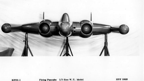
Langley Full-Scale Tunnel Investigation of a 1/3-Scale Model of the Chance Vought XF5U-1 Airplane
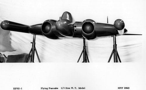
The results of an investigation of a 1/3-scale model of the Chance Vought XF5U-1 airplane in the Langley full-scale tunnel are presented in this report. The maximum lift and stalling characteristics of several model configurations, the longitudinal stability characteristics of the model, and the effectiveness of the control surfaces were determined with the propellers removed. The propulsive characteristics, the effect of propeller operation on the lift, and the static thrust of the model propellers were determined at several propeller-blade angles. The results with the propellers removed showed that the maximum lift coefficient of the complete model configuration was only 0.97 was compared with the value of 1.31 for the model configuration in which the engine-air ducts and canopy are removed. The model with the propellers removed (normal center-of-gravity position) has a positive static margin, stick fixed, varying from 5 to 13 percent of the mean aerodynamic chord throughout the unstalled range of lift coefficients. The unit horizontal tail is sufficiently powerful to trim the airplane with the propellers removed throughout the unstalled range of lift coefficients. The peak propulsive efficiencies for beta = 20 degrees and beta = 30 degrees were increased 7 percent at C(sub L) congruent to 0.67 and 20 percent at C(sub L) congruent to 0.74, respectively, with the propellers rotating upward in the center than with the propellers rotating downward in the center. Indications are that the minimum forward-flight speed of the airplane for full-power operation at sea level will be about 90 miles per hour. Decreasing the weight and increasing the power reduced this value of minimum speed and there were no indications from the results of a lower limit to the minimum speed.
Publication Date: Oct 11, 1946
http://ntrs.nasa.gov/archive/nasa/casi.ntrs.nasa.gov/20050019375.pdf
- Joined
- 3 June 2006
- Messages
- 3,094
- Reaction score
- 3,966
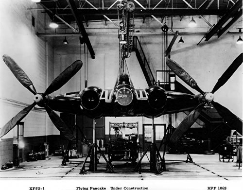
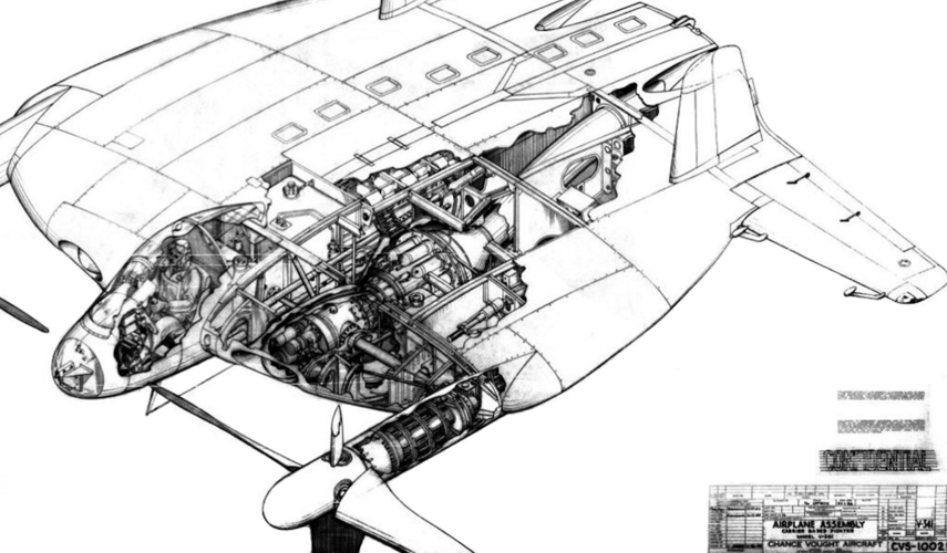
Source: http://aviationarchives.blogspot.com/2018/02/vought-xf5u-flying-flapjack-illustrated.htmlRon Downey said:Vought XF5U Flying Flapjack Illustrated Assembly Breakdown
A copy of the Illustrated Assembly Breakdown for the Vought XF5U Flying Flapjack aircraft. Dated 1 January 1945.
Credit: Ed Seay Jr., M-A-L Hobby Shop, Irving, TX, via Michael McMurtrey
Click here to download breakdown (3.8 Megs)
Alternate download here
SleeperService2
Not sure about changing it now.
- Joined
- 16 August 2016
- Messages
- 70
- Reaction score
- 97
Very interesting speculative drawings there and timely as I'm looking at a part-built 1/48 model right now and wondering what to do with it. I've been looking at this image

and thinking of the turboprop Meteor

I think offsetting the engine a little further outboard would allow the jet pipe a straight run to the rear making the most of the residual thrust while also allowing extra fuel tanks inboard to maintain a reasonable range.
The big selling point of the concept was the counter-rotating propellers' ability to disrupt the tip vortexes and thus remove a significant amount of drag. The large offset and length of the jet pipe would reduce thrust considerably, taken together I doubt a pure jet engine could work in this airframe.
Beautiful drawings though and Thank You for posting them up.")
N

and thinking of the turboprop Meteor

I think offsetting the engine a little further outboard would allow the jet pipe a straight run to the rear making the most of the residual thrust while also allowing extra fuel tanks inboard to maintain a reasonable range.
The big selling point of the concept was the counter-rotating propellers' ability to disrupt the tip vortexes and thus remove a significant amount of drag. The large offset and length of the jet pipe would reduce thrust considerably, taken together I doubt a pure jet engine could work in this airframe.
Beautiful drawings though and Thank You for posting them up.
N
blackkite
Don't laugh, don't cry, don't even curse, but.....
- Joined
- 31 May 2007
- Messages
- 8,819
- Reaction score
- 7,718
Very interesting speculative drawings there and timely as I'm looking at a part-built 1/48 model right now and wondering what to do with it. I've been looking at this image
View attachment 642762
and thinking of the turboprop Meteor
View attachment 642763
I think offsetting the engine a little further outboard would allow the jet pipe a straight run to the rear making the most of the residual thrust while also allowing extra fuel tanks inboard to maintain a reasonable range.
The big selling point of the concept was the counter-rotating propellers' ability to disrupt the tip vortexes and thus remove a significant amount of drag. The large offset and length of the jet pipe would reduce thrust considerably, taken together I doubt a pure jet engine could work in this airframe.
Beautiful drawings though and Thank You for posting them up.
N
blackkite
Don't laugh, don't cry, don't even curse, but.....
- Joined
- 31 May 2007
- Messages
- 8,819
- Reaction score
- 7,718
Hi!
https://oldmachinepress.com/2017/02/05/vought-xf5u-flying-flapjack/
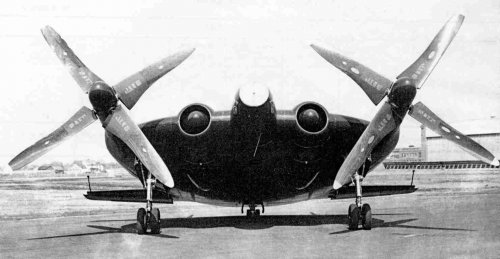
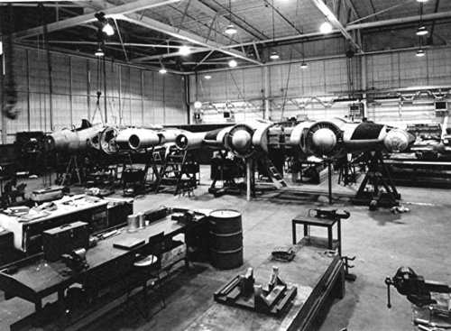
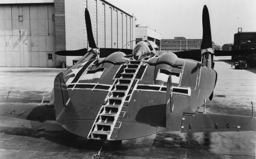
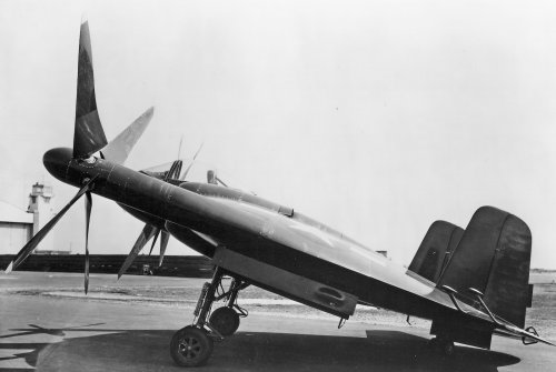
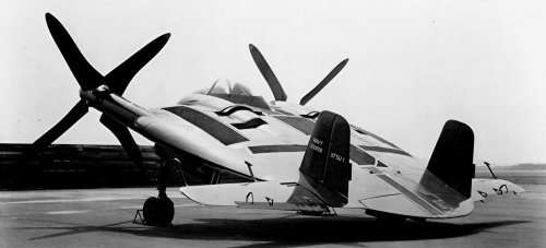
"Originally, the XF5U was to be powered by two 14-cylinder, 1,600 hp (1,193 kW) Pratt & Whitney (P&W) R-2000-2 engines. It appears P&W stopped development of the -2 engine, and the 1,350 hp (1,007 kW) R-2000-7 was substituted sometime in 1945. The engines were buried in the aircraft’s fuselage, and engine-driven cooling fans brought in air through intakes in the aircraft’s leading edge. Cooling air exit flaps were located on the engine nacelles on both the upper and lower fuselage. An exit flap for intercooler air was located farther back on the top side of each nacelle."
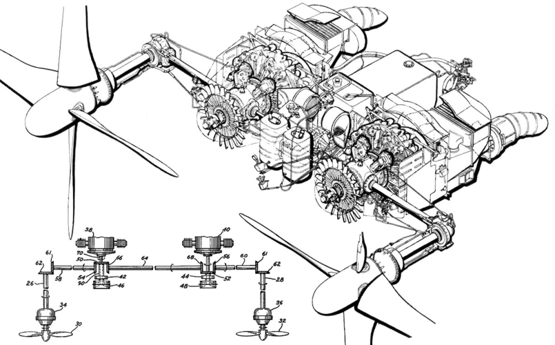
"To bring the XF5U into the jet age, Vought designed the turbine-powered VS-341. The aircraft had the same basic layout as the XF5U. Note the power cross shaft extending from the gearbox toward the other engine."
https://oldmachinepress.com/2017/02/05/vought-xf5u-flying-flapjack/
"Originally, the XF5U was to be powered by two 14-cylinder, 1,600 hp (1,193 kW) Pratt & Whitney (P&W) R-2000-2 engines. It appears P&W stopped development of the -2 engine, and the 1,350 hp (1,007 kW) R-2000-7 was substituted sometime in 1945. The engines were buried in the aircraft’s fuselage, and engine-driven cooling fans brought in air through intakes in the aircraft’s leading edge. Cooling air exit flaps were located on the engine nacelles on both the upper and lower fuselage. An exit flap for intercooler air was located farther back on the top side of each nacelle."
"To bring the XF5U into the jet age, Vought designed the turbine-powered VS-341. The aircraft had the same basic layout as the XF5U. Note the power cross shaft extending from the gearbox toward the other engine."
Attachments
Last edited:
blackkite
Don't laugh, don't cry, don't even curse, but.....
- Joined
- 31 May 2007
- Messages
- 8,819
- Reaction score
- 7,718
Attachments
Excellent ! A turbine variant... what were the turboprops ? I dream of a modern-day Flying Flapjack with PT-6s.
Turboprops make tons of sense... keep the propellers giving it superb VSTOL capability, at much less weight and complexity...
Turboprops make tons of sense... keep the propellers giving it superb VSTOL capability, at much less weight and complexity...
Modern turbines might make more sense. But tons? The engines were hardly the most complex and challenging part of the design. The cross-shafting, the flapping propeller blades, and all that gearing would probably be development and servicing nightmares even today.Excellent ! A turbine variant... what were the turboprops ? I dream of a modern-day Flying Flapjack with PT-6s.
Turboprops make tons of sense... keep the propellers giving it superb VSTOL capability, at much less weight and complexity...
In the 1940s, turbines were only theoretically simpler and more reliable than piston engines. So at that time, piston engines were the highly developed, reliable, well-understood part of a complex, still largely untested powertrain and airframe.
In any case, in 1945, even solidly reliable turbines would not have been enough to give the F5U a future. Rightly or wrongly, the USN had no requirement for a VSTOL fighter. It had a fleet of large carriers, with bigger ones still to come. These could operate conventional fast jets and large bombers capable of competing with those of the new USAF. Any VTOL requirements could be met by marginally less complex, piston-engined helicopters. A specialized VSTOL Navy fighter would, at best, distract from the post-war competition for funding and, at worst, play into the hands of the land-based Air Force.
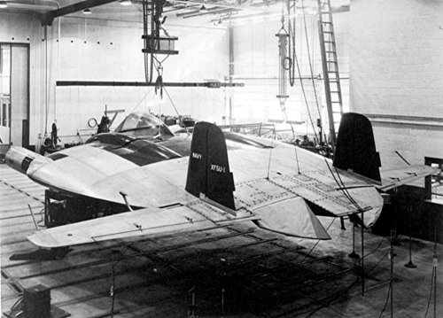
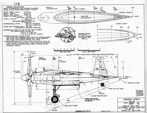
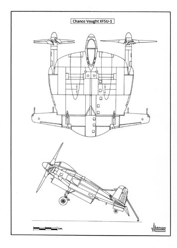
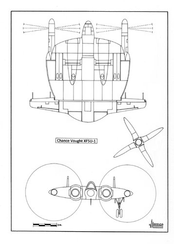
On January 19, 1942 Vought-Sikorsky submitted to the U.S. Navy the VS-315 proposal for a 425 mph STOL fighter. In February, the Navy requested a 1/3 scale wind-tunnel model, the VS-315 receiving the official designation XF5U-1 on September 10, 1942 and the wooden mock-up VS-313 was finished in June 1943.
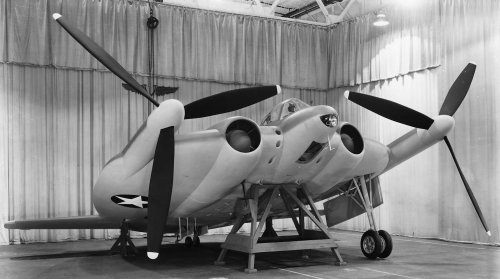
The projected naval fighter had a lightweight aluminum structure with Metalite/ balsa/aluminum sandwich skin, 20 times as much power that the V-173 and increased top speed/landing speed ratio from a typical 4:1 to 10:1. Using two Pratt & Whitney R-2800-7 radial engines, rated at 1,350 hp. each, was expected a landing speed of 40 mph, a top speed of 425 mph. and a zero-roll take-off with a 25-knot headwind.
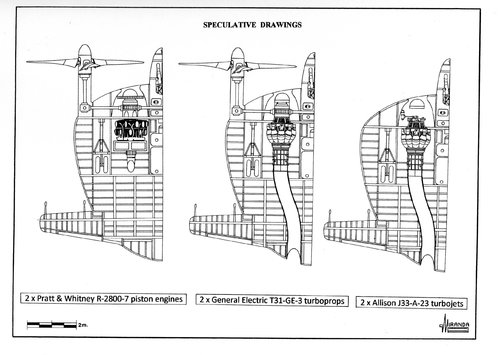
Powered by two 1,600 hp. P&W R-2000-2(D) turbo-supercharged engines with water injection, it was expected to reach 20 to 460 mph and 0 to 550 mph using two General Electric T31-GE-3 turboprops with 2,300 shp+600 lbf residual thrust and greater power-to-weight ratio. The proposed turbine-powered model was designated VS-341. With sufficient power, both rotors could generate more lift than weight for vertical take-off and landing operation, just keeping up with the warship forward speed. Powered by two turboprops, the airplane would hover motionless hanging under its rotors like a helicopter.
On July 29, 1948, the President approved construction of five supercarriers, with 68,250-ton displacement and 1,090 ft (330 m) length, able to carry a group of large nuclear bombers, the most effective weapon of the day, and a new type of swept wing fighters of the F-86 class.
The construction of the USS United States (CVA-58) started on April 19, 1949 with an estimated cost of US $ 189 million, but the USAAF managed to cancel the entire program in favor of the B-36 intercontinental bomber, at the cost of US $ 5.76 million for each plane.
With this operation, the Strategic Air Command kept its monopoly on nuclear weapons delivery until the approval by the Congress of the new USS Forrestal (CVA-59) in April 1950.
During that time, the US Navy was forced to operate with the Essex and Midway-class carriers, straight wing fighters and Lockheed P2V-3C Neptune medium bombers.
After the failure of the Pirate and trying to keep alive its 15 years of work project, Zimmerman proposed to Vought an increased performance version of the XF5U, (labelled as Jet Skimmer in the specialized literature) powered by two Allison J33-A-23 turbojets, rated at 5,400 lbf with water injection. Those huge centrifugal engines, with 50.5 in (128.3 cm) of diameter could not be installed in any naval fighter in service, but they could be buried into the wing/body of the XF5U.
Doubling the power of the F-80C Shooting Star fighter and flying without the extra drag and weight of rotors and gearing, the new plane might have been a 20 per cent faster than the XF5U, but still inferior to the MiG-15 top speed, because the drag penalty induced by their wingtip vortex.
The Jet Skimmer would have retained some of the STOL of the XF5U capability thanks to the special design of its exceptionally low aspect ratio wing. Fitted with the original landing gear and tail hook equipment it might have been able to operate from any escort carrier, but Vought preferred to continue with the development of the V-346 Cutlass, a decision that the Navy would soon regret after the loss of 78 airplanes in accidents.
The projected naval fighter had a lightweight aluminum structure with Metalite/ balsa/aluminum sandwich skin, 20 times as much power that the V-173 and increased top speed/landing speed ratio from a typical 4:1 to 10:1. Using two Pratt & Whitney R-2800-7 radial engines, rated at 1,350 hp. each, was expected a landing speed of 40 mph, a top speed of 425 mph. and a zero-roll take-off with a 25-knot headwind.
Powered by two 1,600 hp. P&W R-2000-2(D) turbo-supercharged engines with water injection, it was expected to reach 20 to 460 mph and 0 to 550 mph using two General Electric T31-GE-3 turboprops with 2,300 shp+600 lbf residual thrust and greater power-to-weight ratio. The proposed turbine-powered model was designated VS-341. With sufficient power, both rotors could generate more lift than weight for vertical take-off and landing operation, just keeping up with the warship forward speed. Powered by two turboprops, the airplane would hover motionless hanging under its rotors like a helicopter.
On July 29, 1948, the President approved construction of five supercarriers, with 68,250-ton displacement and 1,090 ft (330 m) length, able to carry a group of large nuclear bombers, the most effective weapon of the day, and a new type of swept wing fighters of the F-86 class.
The construction of the USS United States (CVA-58) started on April 19, 1949 with an estimated cost of US $ 189 million, but the USAAF managed to cancel the entire program in favor of the B-36 intercontinental bomber, at the cost of US $ 5.76 million for each plane.
With this operation, the Strategic Air Command kept its monopoly on nuclear weapons delivery until the approval by the Congress of the new USS Forrestal (CVA-59) in April 1950.
During that time, the US Navy was forced to operate with the Essex and Midway-class carriers, straight wing fighters and Lockheed P2V-3C Neptune medium bombers.
After the failure of the Pirate and trying to keep alive its 15 years of work project, Zimmerman proposed to Vought an increased performance version of the XF5U, (labelled as Jet Skimmer in the specialized literature) powered by two Allison J33-A-23 turbojets, rated at 5,400 lbf with water injection. Those huge centrifugal engines, with 50.5 in (128.3 cm) of diameter could not be installed in any naval fighter in service, but they could be buried into the wing/body of the XF5U.
Doubling the power of the F-80C Shooting Star fighter and flying without the extra drag and weight of rotors and gearing, the new plane might have been a 20 per cent faster than the XF5U, but still inferior to the MiG-15 top speed, because the drag penalty induced by their wingtip vortex.
The Jet Skimmer would have retained some of the STOL of the XF5U capability thanks to the special design of its exceptionally low aspect ratio wing. Fitted with the original landing gear and tail hook equipment it might have been able to operate from any escort carrier, but Vought preferred to continue with the development of the V-346 Cutlass, a decision that the Navy would soon regret after the loss of 78 airplanes in accidents.
That's why I think turboprops would have been almost perfect. Unfortunately, early US ones before the Herk T-56 sucked immensely and ruined way too many projects. Still, the British had the RR Dart, which worked very well. So, how about a reborn F-5U with darts ?
1635yankee
Recovering aeronautical engineer
- Joined
- 18 August 2020
- Messages
- 554
- Reaction score
- 766
YesIsn't the propwash an essential part of the design?
Is there any ACTUAL source for the 'jet skimmer' XF5U-1 development ? (I recall first seeing it as a Wilf Hardy 'what if' drawing in an early 1980's children's magazine page illustrating the V.173/XF5U pancake)
I was under the impression it was a totally 'fictional', or at best 'speculative' concept ?
More than happy to be proven otherwise tho
I was under the impression it was a totally 'fictional', or at best 'speculative' concept ?
More than happy to be proven otherwise tho
Last edited:
Scott Kenny
ACCESS: USAP
- Joined
- 15 May 2023
- Messages
- 11,649
- Reaction score
- 14,358
By the 1950s, Ford had designed a differential that could handle the amount of power being used by the Flapjack. The basic 9" in drag racing configuration is capable of handling something in the neighborhood of 10,000hp. 9" rear differential and a pair of simple 90deg gearboxes would allow a single engine to power both props, with the 9" spool handling the direction of rotation for the props.Modern turbines might make more sense. But tons? The engines were hardly the most complex and challenging part of the design. The cross-shafting, the flapping propeller blades, and all that gearing would probably be development and servicing nightmares even today.
In the 1940s, turbines were only theoretically simpler and more reliable than piston engines. So at that time, piston engines were the highly developed, reliable, well-understood part of a complex, still largely untested powertrain and airframe.
In any case, in 1945, even solidly reliable turbines would not have been enough to give the F5U a future. Rightly or wrongly, the USN had no requirement for a VSTOL fighter. It had a fleet of large carriers, with bigger ones still to come. These could operate conventional fast jets and large bombers capable of competing with those of the new USAF. Any VTOL requirements could be met by marginally less complex, piston-engined helicopters. A specialized VSTOL Navy fighter would, at best, distract from the post-war competition for funding and, at worst, play into the hands of the land-based Air Force.
I think you'd need to use HH3 or maybe even HH53 90deg tail rotor drive boxes to handle 1600+hp each, though.
Scott Kenny
ACCESS: USAP
- Joined
- 15 May 2023
- Messages
- 11,649
- Reaction score
- 14,358
There's some chatter from the USAF during the 1940s flying saucer panic "Are we SURE the Navy cancelled the Flapjack?"Is there any ACTUAL source for the 'jet skimmer' XF5U-1 development ? (I recall first seeing it as a Wilf Hardy 'what if' drawing in an early 1980's children's magazine page illustrating the V.173/XF5U pancake)
I was under the impression it was a totally 'fictional', or at best 'speculative' concept ?
More than happy to be proven otherwise tho
But to everything I have read the XF5U was always a piston pounder, not even a jet booster like the Ryan FR-1 Fireball or the late proposal for the XP-67 Moonbat.
If the USN had stuck with the Flapjack I'd bet it would have gotten re-engined with turboprops, but chances were good it would have been saddled with the T38/T40 duds like everything else the Navy was planning on.
- Joined
- 31 December 2006
- Messages
- 803
- Reaction score
- 363
Well, the current “highly improved” Ford 9-inch equivalents use CAD, lubricants, and metallurgy that were unavailable in the 1940s, and have a duty cycle of four seconds. Pretty sure we’re talking apples and kumquats here.By the 1950s, Ford had designed a differential that could handle the amount of power being used by the Flapjack. The basic 9" in drag racing configuration is capable of handling something in the neighborhood of 10,000hp. 9" rear differential and a pair of simple 90deg gearboxes would allow a single engine to power both props, with the 9" spool handling the direction of rotation for the props.
Last edited:
Scott Kenny
ACCESS: USAP
- Joined
- 15 May 2023
- Messages
- 11,649
- Reaction score
- 14,358
I have seen the 9" center sections used in endurance racers.Well, the current “highly improved” Ford 9-inch equivalents use CAD, lubricants, and metallurgy that were unavailable in the 1940s, and have a duty cycle of four seconds. Pretty sure we’re talking apples and kumquats here.
- Joined
- 31 December 2006
- Messages
- 803
- Reaction score
- 363
But not at 10,000 HP.I have seen the 9" center sections used in endurance racers.
Scott Kenny
ACCESS: USAP
- Joined
- 15 May 2023
- Messages
- 11,649
- Reaction score
- 14,358
Would only need to be at about 3000hp unless you were evil enough to stick a single T56, AE2100 or gods forbid an Osprey engine in there.But not at 10,000 HP.
The XF5U was planned to use a total of 2800hp, so you could use a single CT7A-7, the T700's bigger brother and have plenty of power.
Aircraft propeller drive systems and automotive differentials are entirely different things.
There's no reason you'd want the propellers driven at different speed and a propeller
acting in the air is not the same as a wheel operating in contact with the ground.
There's no reason you'd want the propellers driven at different speed and a propeller
acting in the air is not the same as a wheel operating in contact with the ground.
- Joined
- 11 March 2012
- Messages
- 3,250
- Reaction score
- 3,179
Turboprops would have almost eliminated much for the vibration and most of the torsional vibration problems that plauge pisotn engines turning long shafts.That's why I think turboprops would have been almost perfect. Unfortunately, early US ones before the Herk T-56 sucked immensely and ruined way too many projects. Still, the British had the RR Dart, which worked very well. So, how about a reborn F-5U with darts ?
Note the helicopters really only became practical after smooth-running turbo-shafts were introduced during the 1950s.
1635yankee
Recovering aeronautical engineer
- Joined
- 18 August 2020
- Messages
- 554
- Reaction score
- 766
To minimize noise, one wants the propellers to not only have the same angular speed but also to have have the propellers in the same phase, so the blades are all in the same relative position at all times.
If one has two (or more) propellers (or helicopter rotors) connected by cross-shafting, there will be no differential: one wants the same rpm everywhere. The only time I've heard of differentials being considered for propellers is for coaxial, counter-rotating propellers, where they maintain the same torque in both propellers and match rpm by adjusting blade pitch.
If one has two (or more) propellers (or helicopter rotors) connected by cross-shafting, there will be no differential: one wants the same rpm everywhere. The only time I've heard of differentials being considered for propellers is for coaxial, counter-rotating propellers, where they maintain the same torque in both propellers and match rpm by adjusting blade pitch.
Nik
ACCESS: Top Secret
- Joined
- 15 July 2009
- Messages
- 1,269
- Reaction score
- 1,063
Sad, really: There was that 'Atlantic Gap' with the disposable 'HurriCats' where STOL 'Flying Pancakes' could have made a serious difference. (*) But that 'ecological niche' closed when 'escort' carriers filled the Gap, then 'mega-carriers' could launch ruddy squadrons of 'ordinary' aircraft, became big enough to carry jets...
*) It's one of those alt-History What-Ifs: Condor and U-Boot crews reporting devastating attacks by 'Amis Flying Saucers' ...
*) It's one of those alt-History What-Ifs: Condor and U-Boot crews reporting devastating attacks by 'Amis Flying Saucers' ...
Scott Kenny
ACCESS: USAP
- Joined
- 15 May 2023
- Messages
- 11,649
- Reaction score
- 14,358
So you use a spool instead of a differential. One simple gear pair, the ring and pinion. That's it.Aircraft propeller drive systems and automotive differentials are entirely different things.
There's no reason you'd want the propellers driven at different speed and a propeller
acting in the air is not the same as a wheel operating in contact with the ground.
(edit) No differential gearing at all, just the nice big 9" ring gear and pinion gear to match. Axles solidly connected on both sides to the ring gear, a drag racer's "spool" locked differential. Though with a standard 9", you'd need to change the gear ratio to something very un-automotive. If your turbine output shaft RPM is about 6000, you'd want a gear ratio of about 2.73:1 to give your props a 2200rpm speed.
Last edited:
Turboprops would have almost eliminated much for the vibration and most of the torsional vibration problems that plauge pisotn engines turning long shafts.
Note the helicopters really only became practical after smooth-running turbo-shafts were introduced during the 1950s.
Hmmm.. Rolls Royce Dart... what might have been.
American turboprop list by Wikipedia. T38 sounds the logical choice - provided it worked well.
Scott Kenny
ACCESS: USAP
- Joined
- 15 May 2023
- Messages
- 11,649
- Reaction score
- 14,358
That would have been hilarious. And the Flapjack was planned for 6x .50cals, so it could have packed 4x 20mm just as easily. Plus 2x 1000lb bombs (ouch). The downside would have been no rockets, not with the prop arcs blocking basically everything.Sad, really: There was that 'Atlantic Gap' with the disposable 'HurriCats' where STOL 'Flying Pancakes' could have made a serious difference. (*) But that 'ecological niche' closed when 'escort' carriers filled the Gap, then 'mega-carriers' could launch ruddy squadrons of 'ordinary' aircraft, became big enough to carry jets...
*) It's one of those alt-History What-Ifs: Condor and U-Boot crews reporting devastating attacks by 'Amis Flying Saucers' ...
I'm really surprised that nobody dug out the Flapjack design for the DARPA TERN UAV program. Super short STOL capabilities, able to hang the entire aircraft off the props, and what should have produced really good speeds.
Similar threads
-
-
 Little-known Vought projects from World War II
- Started by Antonio
- Replies: 71
-

-
-