
You are using an out of date browser. It may not display this or other websites correctly.
You should upgrade or use an alternative browser.
You should upgrade or use an alternative browser.
Bell XP-83 (Model 40)
- Thread starter Steve Pace
- Start date
- Joined
- 2 August 2006
- Messages
- 3,300
- Reaction score
- 1,785
Thanks for all of the pics, I always liked this plane. It sort of reminds me of an early jet era Thunderbolt. I find it funny how it was dismissed since it's performance was the same as the P-80's, except it had range. Yet in the early jet era, one of the biggest problems was always a lack of range. Though I do understand that the technology was advancing so rapidly back then, that by the time this would have went into production they probably would have been ready for the F-86.
Does anyone know if engineering drawings of it still exist?
Does anyone know if engineering drawings of it still exist?
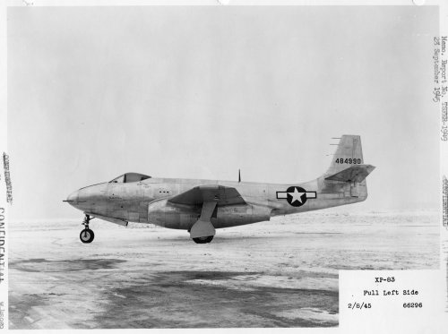
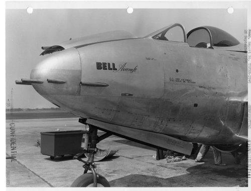
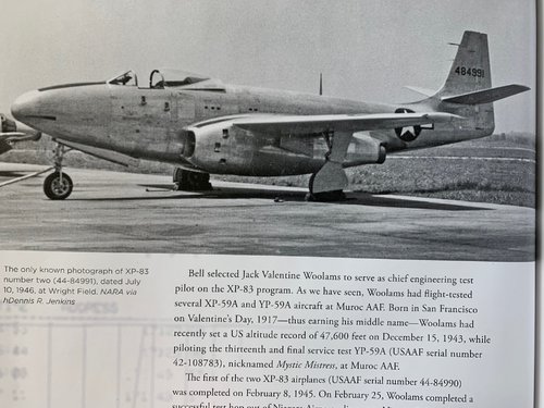
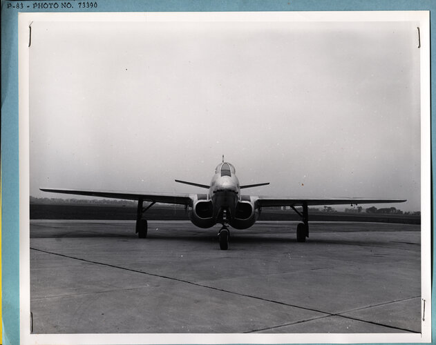
"The second prototype (44-84991) flew on October 19, 1945. It had a slightly different bubble canopy and a somewhat longer nose to accommodate a heavier armament of six 0.60-inch T17E3 machine guns. This aircraft was used in gunnery tests at Wright Field in Ohio."
Attachments


- Joined
- 13 June 2007
- Messages
- 2,220
- Reaction score
- 3,541
Greetings All -
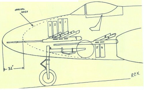
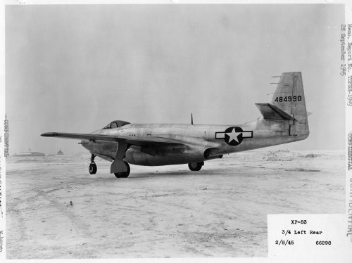
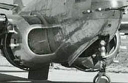
Here are three photos from the Gerald Balzer Collection of Ship #1. Good detail shot of the nose section. Note the dates on the photos....
Enjoy the Day! Mark
Here are three photos from the Gerald Balzer Collection of Ship #1. Good detail shot of the nose section. Note the dates on the photos....
Enjoy the Day! Mark
Attachments
Steve Pace
Aviation History Writer
- Joined
- 6 January 2013
- Messages
- 2,266
- Reaction score
- 262
- Joined
- 16 February 2013
- Messages
- 132
- Reaction score
- 611
Steve Pace had me proof read his last book “The Big Book of X Bombers and X Fighters” in which he published the photo of the second prototype thanks to Jenkins passing it to Tailspin Turtle as shown above in 2011. I wrote the 1981 Airpower article and the original color cutaway was returned to the owner back in the ‘80s’ so we only have access to what was published. Second prototype armed with two .60 cal mg.
Attachments
- Joined
- 31 July 2013
- Messages
- 619
- Reaction score
- 1,300
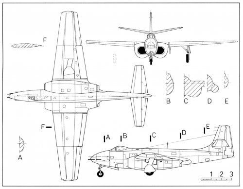
While doing a bit of research on the Bell XP-83 I came across this NACA report on spin trials carried out in a wind tunnel, which may be of interest to forum members; https://digital.library.unt.edu/ark:/67531/metadc61570/m1/1/. Of particular note to me was the drawing showing an original short tail fin and also an extended tail fin, something that I had not been aware of before.


- Joined
- 6 November 2010
- Messages
- 6,025
- Reaction score
- 7,579
Another thread in Aviation & Space: https://www.secretprojects.co.uk/threads/bell-xp-83-model-40.8271/#post-73187
Merge?
Merge?
- Joined
- 28 November 2006
- Messages
- 731
- Reaction score
- 853
Another thread in Aviation & Space: https://www.secretprojects.co.uk/threads/bell-xp-83-model-40.8271/#post-73187
Merge?
Merge.
Of course !
Last edited by a moderator:
- Joined
- 31 July 2013
- Messages
- 619
- Reaction score
- 1,300
Do you know I tried to link these two sections up but there is massive distortion unfortunatelyHere's the scan from Joe Starns. -SP

- Joined
- 3 September 2006
- Messages
- 1,521
- Reaction score
- 1,640
Steve can't answer you. In case you missed it, see thread https://www.secretprojects.co.uk/threads/rip-steve-pace.27262/
KHambsch
ACCESS: Confidential
- Joined
- 11 May 2020
- Messages
- 180
- Reaction score
- 203
They look like Marquardt RJ twenties to me alsosagallacci: are you sure that those aren't the Marquardt 20" diameter ramjets?
Marquardt Aircraft used 44-84990 as a ramjet testbed (complete with a rear fuselage engineer’s station -- visible in the photo above).
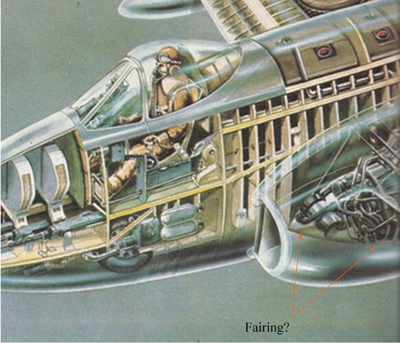
I have just started an Anigrand Bell XP-83 and found an error. In the engine nacelle there is a part representing the compressor face. There is no such thing in the a/c as it has a centifrugal compressor. Pictures of the J-33 show a mass of pipes and equipment before the intake. When installed in the a/c was this protected by some sort of bullet fairing or was it left out in the breeze? A cutaway drawing in Steve Pace's 'X Fighters' book suggests the latter.
Can anyone please enlighten me?
John
Can anyone please enlighten me?
John
Most photos of XJ-33 GE-5 just show a mass of pumps and tubes on the front of the engine. Most early centrifugal compressor engines had few internal fairings. Air flow was so turbulent by the time it reached the compressor face, that fairings would make little difference.I have just started an Anigrand Bell XP-83 and found an error. In the engine nacelle there is a part representing the compressor face. There is no such thing in the a/c as it has a centifrugal compressor. Pictures of the J-33 show a mass of pipes and equipment before the intake. When installed in the a/c was this protected by some sort of bullet fairing or was it left out in the breeze? A cutaway drawing in Steve Pace's 'X Fighters' book suggests the latter.
Can anyone please enlighten me?
John
That matches my experience working on Rolls-Royce engines in CF-133s flown by the Canadian Air Forces. T-33 might have had gracefully sloped inlets along the fuselage, but they just opened into a huge plenum chamber (most of the fuselage cross-section) lined with cables, pumps, etc. This allowed mechanics to quickly access to pumps, generators, cables, hoses, etc. A couple of blow-in doors, on top, admitted extra air during ground running.
Thank you. I was not concerned about the quality of the air going into the intake, only about the effect of all that air blowing on the ancillary equipment.
When I looked at centrifugal flow engines there was so much of that equipment at the forward end that I often found it difficult to work out where the air went in.
When I looked at centrifugal flow engines there was so much of that equipment at the forward end that I often found it difficult to work out where the air went in.
Air enters the engine through conical screens that lay between the accessory case and burner cans. If the engine has two centrifugal compressors, then it gets two conical wire mesh screens, back to back.
Yes, but sometimes the screens are painted black or they are not present when the unit is photographed or displayed. Also on those early units the intake area was fairly small. It is easier to see them once you know where to look.Air enters the engine through conical screens that lay between the accessory case and burner cans. If the engine has two centrifugal compressors, then it gets two conical wire mesh screens, back to back.
I've been doing a lot of research on the XP-83s so that I can correct the Anigrand 1/72 resin model.
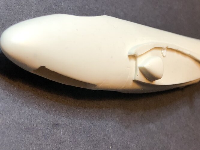
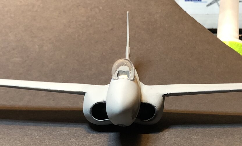
Regarding the intakes, it appears that you would not be able to see any of the engine (without sticking your head in the inlet, anyway) because it looks like they had an intake "cone" that was very similar to the P-59.
Find pictures of the P-59 intake - it has a sort of flattened cone that results in a horizontal line when viewed from the front. Think of a cheese wedge laying on its side, sort of. There are several pictures of the XP-83 that reveal a horizontal line in this location, so I think it's a pretty good bet that the XP-83 inlet cone is very similar (maybe identical) to that on the P-59.
I used a casting of a P-59 inlet cone in my XP-83 model and it fits very nicely (see photo).
There is also a bleed inlet at the front of the intake, like on most jets.
The Anigrand intakes are too short and squared-off. The real thing was a bit longer and was rounder on the top corner and extended just slightly over the leading edge of the wing.
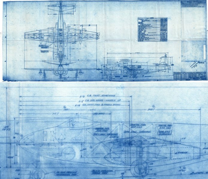
I got hold of a factory blueprint on-line (I'll dig around for the website) and it was very revealing. More to come...
Regarding the intakes, it appears that you would not be able to see any of the engine (without sticking your head in the inlet, anyway) because it looks like they had an intake "cone" that was very similar to the P-59.
Find pictures of the P-59 intake - it has a sort of flattened cone that results in a horizontal line when viewed from the front. Think of a cheese wedge laying on its side, sort of. There are several pictures of the XP-83 that reveal a horizontal line in this location, so I think it's a pretty good bet that the XP-83 inlet cone is very similar (maybe identical) to that on the P-59.
I used a casting of a P-59 inlet cone in my XP-83 model and it fits very nicely (see photo).
There is also a bleed inlet at the front of the intake, like on most jets.
The Anigrand intakes are too short and squared-off. The real thing was a bit longer and was rounder on the top corner and extended just slightly over the leading edge of the wing.
I got hold of a factory blueprint on-line (I'll dig around for the website) and it was very revealing. More to come...
Attachments
Last edited:
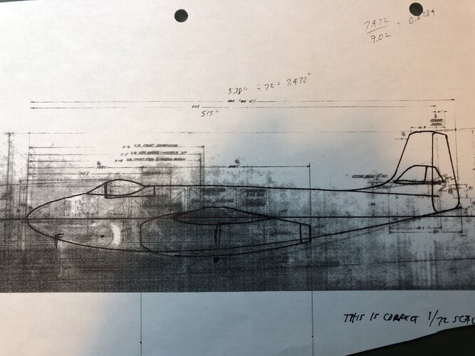
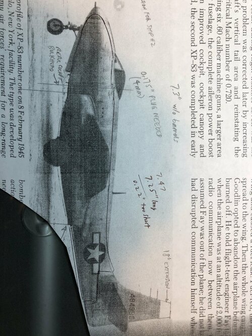
Regarding the vertical tail of the XP-83, every written source that I have found claims that the second prototype had an 18 inch extension to the tail. As you can see in the drawing earlier in this thread, the XP-83 originally had a rather short tail, like a P-59A. That is also what is depicted in the factory blueprint that I found.
As mentioned above, spin tests at NACA showed the need for increased vertical fin area. I suspect that the 18 inch extension was a revision to the original design and that the tail shown in photos of the XP-83 #1 and #2 both already had this extension when they were built. In other words, the spin tests referred to above were performed on models in the wind tunnel before the first flight of XP-83 #1.
So there is probably the original short tail, as seen in drawings only, and the extended tail, as seen in every available photograph of both XP-83s
Here is an outline of the original design over the blueprint (which is kind of faint):
Attachments
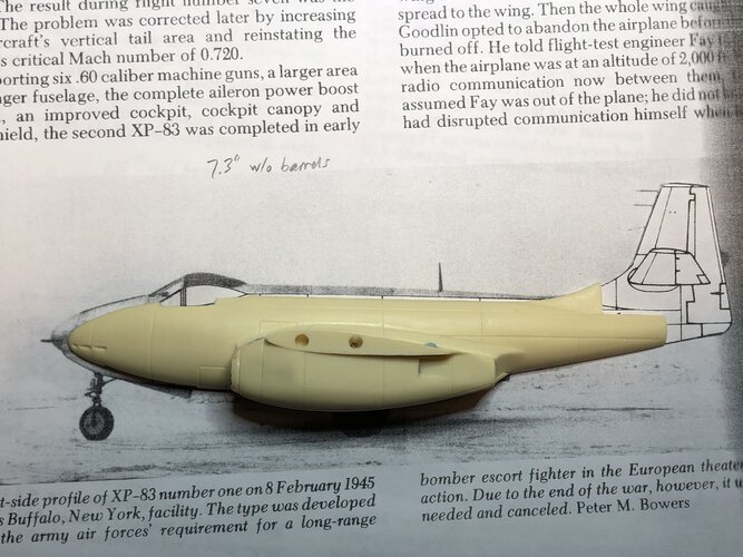
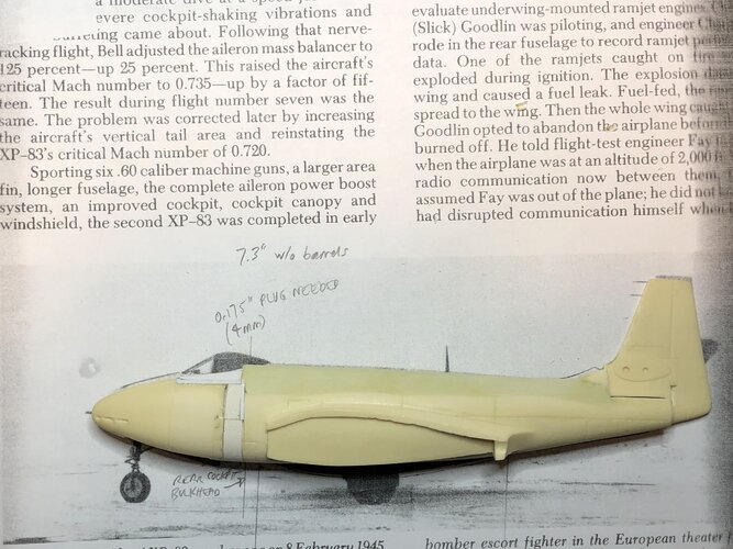
As for the 1/72 Anigrand XP-83 model, it has some good features - the wing planform is mostly right (wingtips are just a bit too round) and the parts fit nicely. The fuselage never looked right, to me, however.
Here is an overlay of the Anigrand resin fuselage over a very nice side view of the XP-83. It clearly shows that the Anigrand fuselage is not deep enough in the keel (it's not "tall" enough). The reason is that there is not enough height above the wings - the spine needs to be extended upward.
The Anigrand model does match the 3-view drawing from Lloyd Jones' U.S. Fighters book pretty well - I suspect that was their primary source. It's a great book which I often refer to, but some of the drawings are not very accurate. Another potential problem may be that when quoting the length of an aircraft, it is not always obvious whether the stated length includes pitot tubes, probes, antennae or gun barrels. The blueprint makes it clear that the length of the XP-83 does NOT include the gun barrels. Again, I suspect that Anigrand underestimated the length of the XP-83 by including the gun barrels in their length.
What the overlay shows is that in order to correct the Anigrand model, the fuselage needs to be extended and the spine needs to be raised. The lower fuselage/wing/nacelle relationship is just fine, which is great as it would otherwise be a lost cause.
You may note that in the overlay drawing I showed an additional 18 inch extension to the tail. This was before I found the factory blueprint or saw a photo of XP-83 #2. I'm now convinced that extra 18 inch extension is a red herring.
Attachments
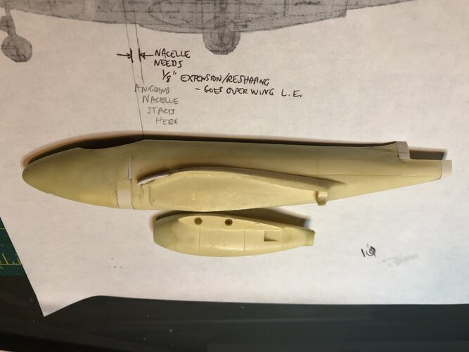
One more thing on the XP-83 intakes. The boundary layer control inlets were not flat the way they are depicted in the Anigrand model. They should follow the curve of the fuselage. Note that none of my model photos include this - I haven't added that detail yet!
Here's the link to the website that offers scans of the XP-83 Bell factory 3-view blueprints (in three different sizes). It was only $3 US. They have some interesting stuff.
Thank you, but I am not sure that I wished to know about all of that! Being interested in experimentals and prototypes, information on which is usually sparse, most of my models involve quite a bit of scratch building or modification and having several projects 'stalled' I thought that just to get something finished I would build the XP-83 'from the box'. Fat chance! Once the engine face caught my attention I noticed the problem with the boundary layer bleeds and have corrected this.
Anigrand models are not renowned for their accuracy but at first sight the XP-83 looked like one of the better ones.
The references I have found give the length as 44ft 10" which agrees with your figure of 538"
That's an interesting comment about the cone in the intake. I had wondered about that 'line' in the intake and now I look at my P-59 I see something similar.
The references I have found give the length as 44ft 10" which agrees with your figure of 538"
That's an interesting comment about the cone in the intake. I had wondered about that 'line' in the intake and now I look at my P-59 I see something similar.
Last edited:
rieleyj, yes, that was also my intent when I pulled my XP-83 model from the cabinet - I thought "this should be easy enough"!
But photos of built models just didn't look right, so I started down the rabbit hole.
If you want to save some time, I made a cast of the revised fuselage which is available on ebay.
I also made a revised canopy that looks a lot more like the real thing.
I also made a XP-83 #2 extended fuselage and longer canopy as an option.
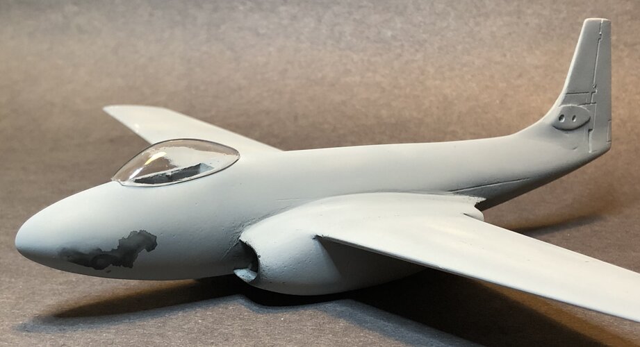
The XP-83 canopy was kind of interesting. Those were the early days of pressurized cockpits and the XP-83 was one of those "evolutionary dead-ends". The bubble canopy was fixed to a section of the upper fuselage skin and the whole assembly raised and slid back as one unit. So if you want to model an XP-83 with the bubble canopy open, you have to include part of the upper fuselage with it.
The windscreen, meanwhile, was also blown out such that it was pinched in at the bottom when viewed from the front.
So the whole canopy bulged out a bit from the fuselage, which can be clearly seen in this photo:
The Anigrand injection-molded canopy isn't too bad, but it is undersized and doesn't bulge out like the real thing.
The XP -83 #2 canopy was a bit longer and extended to the aft edge of the "pop-up" section of the fuselage. See the picture from the March 2020 posting.
Attachments
windswords
ACCESS: Secret
- Joined
- 19 May 2009
- Messages
- 391
- Reaction score
- 240
That looks very similar to the modern F-16 canopy in shape. Was the P-83 a one piece or two piece canopy? The F-16's of course is one piece.The windscreen, meanwhile, was also blown out such that it was pinched in at the bottom when viewed from the front.
So the whole canopy bulged out a bit from the fuselage, which can be clearly seen in this photo:
Attachments
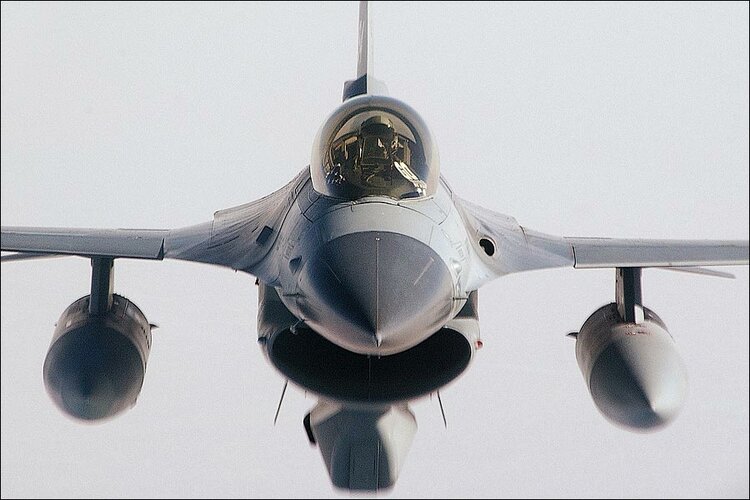
2-piece.That looks very similar to the modern F-16 canopy in shape. Was the P-83 a one piece or two piece canopy? The F-16's of course is one piece.The windscreen, meanwhile, was also blown out such that it was pinched in at the bottom when viewed from the front.
So the whole canopy bulged out a bit from the fuselage, which can be clearly seen in this photo:
The picture posted in March 2020 shows a fixed windshield and a separate main canopy. The main canopy is bolted to an aluminum "skirt" that retracts parallel to the aft fuselage in flight configuration ... similar to many of the modern RV-series of kitplanes.
Here is an outline of the original design over the blueprint (which is kind of faint):
Feh:
Regarding the canopy, there are photos posted on the first page of this discussion that show what the opened canopy looked like on the first XP-83. There is a photo of the longer canopy of the second prototype earlier in this page.
There is an easy alternative to modeling the inside of the intakes - some photos show a "remove before flight" FOD cover blocking the intake! Probably red in color...
There is an easy alternative to modeling the inside of the intakes - some photos show a "remove before flight" FOD cover blocking the intake! Probably red in color...
Similar threads
-
 Boeing XP-12A (Model 101) fighter (1929)
- Started by Triton
- Replies: 0
-
-
-
-
Boeing XP-9 monoplane fighter prototype (Model 96)
- Started by Triton
- Replies: 2