Interesting that you found my old post up there.
I was an MOS 6657, airborne missile fire control technician on F-4J and F-4S Phantom II's during my six-year tour in the Marine Corps.
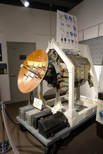
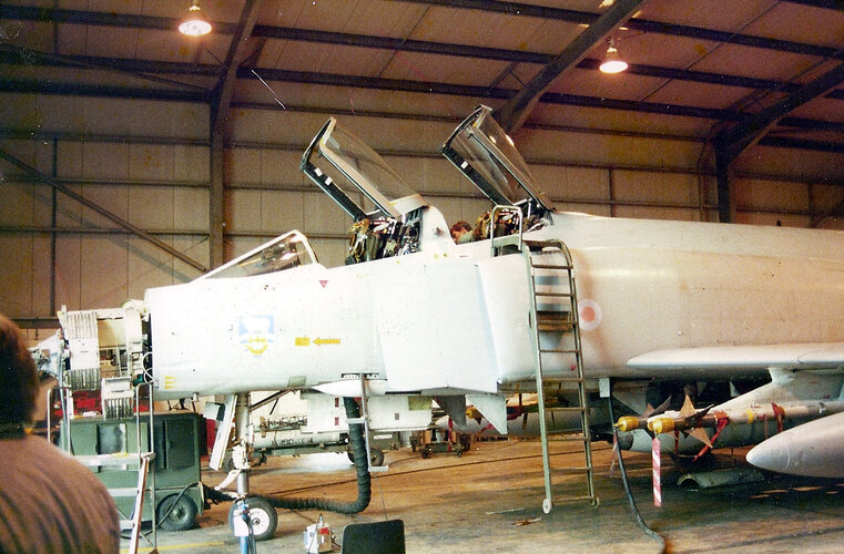
In the top photo, the radar antenna (LRU-1, LRU=Line Replaceable Unit)) has no IFF antennas (Identification, Friend or Foe). On the port side of the antenna (or right side as you're looking at it) is a rectangular funnel-shaped object, which is the CW illuminator feedhorn. The main KPA (Klystron Power Amplifier) is 1525 watts, and the CW illuminator KPA is around 900 watts. It was necessary to provide the illuminator KPA for the AIM-7 Sparrow missiles' guidance, as even though the illuminator KPA was rated at a much lower power than the main KPA, the most the main KPA could be on for TX/RX was less than a 50% duty cycle, reducing it's effective power to well below that of the CW KPA. Signal from the CW KPA was also fed via coaxial cable to the rear of the four onboard missile stations, for the Sparrows to get a "lock" on. Early Sparrows had mechanical tuners, which were problematic; one ordinance technican found that you could get them "unstuck" using a large hammer, which action caused the rest of us more cautious and sane types to scatter in all directions.
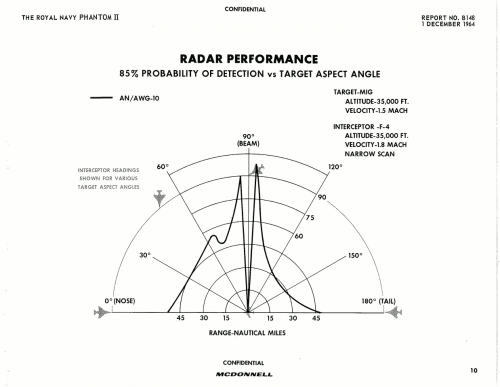
The APG-59/AWG-10 radar had three basic modes:
1) Short Pulse - a 0.65 uSEC pulse triggered the transmitter to send out the same length pulse. This was the 10 NM mode.
2) Chirp - A 0.65 uSEC pulse was sent through a "delay line" - basically, an inductor which was grounded on one end. This caused the inductor to "ring" as a struck bell, and would cause the transmitter to fire for approximately 65 uSEC. Upon returning, the signal would be fed back across this same delay line, which would compress the pulse back down to about 0.8 uSEC pulsewidth prior to being fed to the receiver (LRU-2A8, bottom starboard side). This meant a slight loss in resolution, but a huge gain in range due to the increased return signal.
3) Pulsed Doppler - the most powerful mode. The transmitter would fire for approximately 40 uS, and then the system would receive for approximately 40 uS. The PRF (Pulse Repetition Frequency) would be varied constantly to avoid a phenomenon known as "target eclipsing" (when the transmitter is on while the return signal comes back.)
Back to the LRU-1 photo at the top: Notice that there is a rectangular panel about 1/3 of the way down the antenna? That is the Beam Spoiler, and was used for PPI/MAP mode (Plan Position Indicator) - it would extend about 1" to "spoil" the radiation pattern to scan the ground. On the scope, the sweep would scan back and fourth 120º (+-60º) and the bottom of the scan would be fixed, the top (furthest away) would look like a Japanese fan, or a section of pie, if you will.
In combat modes, the sweep was vertical, traversing the entire screen.
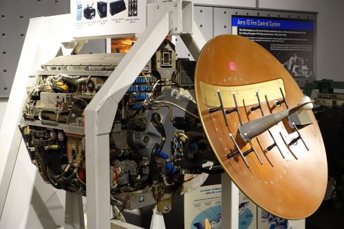
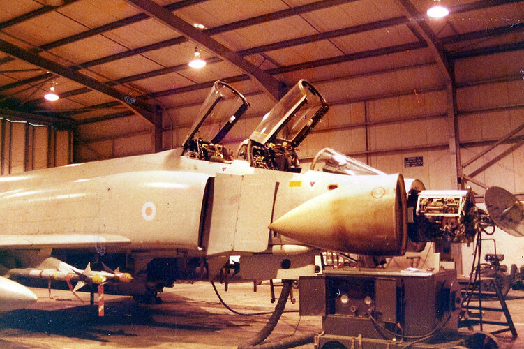
In the 2nd picture, the eight black T-shaped items on the front of the antenna are IFF antennas. They are white on one end (the top) of the "T" to indicate the polarity of the antenna; as putting some of them on backwards would foul up the signal.
The feedhorn is the long projection from the center of the antenna. At the forward end, there are thin fiberglass covers epoxied over the feedhorn, enabling the waveguide system to be pressurized with dry air to 14 lbs/in2 so that the RF energy wouldn't arc (short out) in the waveguide. The feedhorn directed the transmitted energy back against the dish, and received the signal the same way. When the RIO (Radar Intercept Officer) initiated a lock, the feedhorn support would begin to rotate at 66 RPM, causing slight rotational shifts in the position of the feedhorn; this was known as "nutating the feedhorn." This shifting would cause the radar to "paint a donut" around the target. The radar would detect the difference in signal return around the "donut", and re-orient the antenna so that the signal strength was equal all around.
The antenna was controlled by servos and resolvers, but driven by hydraulic pressure. The Phantom's hydraulic system was pressurized to 3,000 PSI, but the antenna's supply was regulated down to 1,200 PSI.
Of all the radars' modes, PD (Pulse Doppler) was the mode that was the hardest to get used to, and somewhat more difficult to fix.
In PD mode, targets were not displayed in range, but in terms of closing velocity, or Vc! Targets near the top of the scope were closing very rapidly, while targets near the bottom were going away. The range was about 1,600 knots closing to about 500 opening. In order to determine the range, the pilot or RIO would have to lock on to the target, and then a range gate would appear as a blip to show range.
The AWG-10A was a big improvement; LRU's 15,16,and 17 (analog computers) in the turtleback (panel 19 behind the RIO) were changed, the new LRU's 15 and 16 were digital, LRU-17 deleted. The analog
version described the missile's envelope as a truncated cone, which was grossly inadequate. The AWG-10A's missile envelope was more like a mushroom, if you will - and much more accurately described the lethal zone of the missiles.
Back to the 2nd picture: the "6" equipment rack is down. LRU-6A2 is on the bottom, LRU-6A1 on top. The 6A1 dealt mostly with antenna control, the 6A2 with the CW illuminator.
To the left (forward) is the "5" equipment rack, and just behind the X-frame is the "4" equipment rack.
On the top of the "4" rack is LRU 4A1, down from there is LRU-4A2, and on the bottom is the LRU-4A3
Inside the LRU-4A2 are 290 crystal ovens, each a different frequency, which resonated to signal returns in the PD mode, thus giving the Vc (velocity closing) range (roughly -500kts to 1500kts)
I realize now that I misspoke in my prior post - it was the 4A1A7 board, not the 4A3A7, that needed to be changed for frequency selection. The 4A3A7 board had it's own problems - there was a block of Zener diodes, which if blown, would cause an effect known as "picket fencing" on the display; the PRF would change every 60 ms causing the display to have vertical streaks on it.
VTAS - (Visual Target Acquisition System) In later versions, VTAS was implemented. The pilot wore a special helmet with four IR transmitters on it, and there were IR receivers mounted around the pilot's cockpit. The pilot's helmet had a reticle; he would extend it over his right eye, and look at the target while pressing half-action on the acquisition switch on his stick. The radar would sweep out in range, and acquire the target. As far as I can remember, this only worked in 10-mile range, or "short pulse". But, like I said - it's been a long time since I've worked on them.
[edited for minor corrections]