overscan (PaulMM)

Administrator
Staff member
Joined
27 December 2005
Messages
16,798
Reaction score
21,100
This radar formed the basis of the AWG-9, and was the first lookdown/shootdown weapons system.

Originally developed for the North American F-108 interceptor, the origins of AN/ASG-18 lie in 1954, when alongside a new interceptor competition a competition was held to design a radar with a 100nm range against a B-47 sized target. 13 proposals were made, of which Hughes and Sperry rated 1st and 2nd, but both designs had only 40nm range from their 40 inch diameter antennas. While the airframe competition withered, the development of the radar systems was continued for future applications. Sperry signed a contract in December 1955, and Hughes in February 1956. Sperrey's system was cancelled in May 1956 due to lack of progress, and replaced by a similar contract to RCA in September 1956. THe Hughes radar was progressing well by comparision, and was studied for a possible production version F-103.

When the long range interceptor program was reinstated in April 1957, it was again desired to have an 80-100nm range radar. North American won the airframe competition in June 1957, and quickly detirmined that the weapons system would need a detection range of 30-40nm for a Mach 1 target, 45-65nm for a Mach 2 target, and 90-110nm for a Mach 3 target. The Hughes radar range was by this time about 50nm. Hughes was ordered to redesign its radar to accomodate the North American requirements. After the F-108 was cancelled, AN/ASG-18 was switched to the YF-12 program.

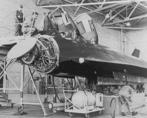
ASG-18 was the first coherent pulse doppler radar. It had a liquid cooled transmitter, formed from 2 TWTs in tandem and analogue circuitry for generating and processing the coherent high PRF waveform. The radar consisted of 41 separate units weighing 2098lbs, and included a digital computer for navigation, firing solutions and BIT, analogue steering computer, and a separate IRST system capable of working cooperatively with the radar. It required 40KVA of power.

Nominally, the range was to be 100nm for a B-47 sized target but in early testing the actual detection range was usually below 40nm. Many improvements were made, and during YF-12 testing, a QB-47 target flying at 1000m was acquired at a staggering 130nm. In other tests, the AN/ASG-18 proved capable of tracking an Atlas D ballistic missile, and maintaining a track on a B-57 during a touch and go landing.

The IRST system was carried in each wing root and was to be capable of detecting a B-47 at 45,000ft at 34.8nm tail on and 10.3nm headon. A Mach 3 bomber would be detectable at 76.5nm at any aspect. Field of view was to be 70 x 140 deg and angular accuracy 1 deg. Initially it used a 7 inch detector and dome and a multi-element telescopic lens comprised of silicon and sapphire elements, but drag was excessive and the diameter was reduced to 6 inches. Hughes started the development process with uncooled lead sulphide (PbS) detectors in the 2-2.5 micron range, but moved to an argon cooled indium antimonide detector sensitive to longer wavelengths (3-5 microns). The final version fitted to the YB-58 and YF-12 was a nitrogen cooled lead selenide system.

Sources:

Paul F Crickmore Lockheed Blackbird: Beyond the Secret Missions, Osprey, 2004
Dennis R. Jenkins & Tony Landis Valkyrie: North American's Mach 3 Superbomber, Speciality Press, 2004
 
Some other sources I haven't got hold of:

JOHNSON, C. L. /LOCKHEED AIRCRAFT CORP., BURBANK, CALIF./.
Journal of Aircraft 1970
0021-8669 vol.7 no.4 (355-359)

http://www.aiaa.org/content.cfm?pageid=406&gTable=japaperimportPre97&gID=44177

(includes a nice picture of the antenna on the first page)

ASFC Historical Publication 61-51-2 Development of Airborne Armament 1910-1961 October 1961
 
The thread I waited for so long!!! I've always been fascinating by this weapon system, but details on the web are scarce.
Wasn't RCA the (not Canadian but american) firm in charge of the Astra-1 radar of the
CF-105 ? Or am I totally wrong ? ???
 
Last edited:
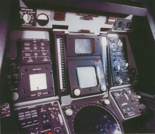
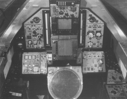
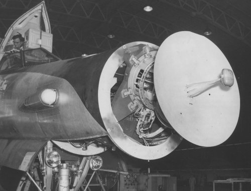
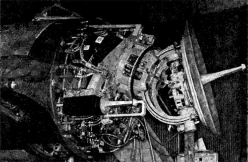
Some pics, sources as above.
 

Attachments

  • ASG-18.jpg
    ASG-18.jpg
    147.9 KB · Views: 403
  • F-108-WSO-Station.jpg
    F-108-WSO-Station.jpg
    154.4 KB · Views: 385
  • YF-12-WSO-Station.jpg
    YF-12-WSO-Station.jpg
    115.5 KB · Views: 371
  • B-58-ASG-18.jpg
    B-58-ASG-18.jpg
    104.5 KB · Views: 351
Sperrey's system was cancelled in May 1956 due to lack of progress, and replaced by a similar contract to RCA in September 1956.

I checked the web : RCA was the builder of the astra-1 radar of the CF-105.
According to Le Fana de l'aviation 273 (august 1992) there was aproposal to fit the AN/ASG-18 in the CF-105, just before its cancellation.
so I'm intrigued... is there a link between the two ? on one hand, RCA was one of the competitor for the early LRIX radar, on the other hand, you have this proposal of early 1959...
 
Well, the AN/ASG-18 and ASTRA were intended to do much the same work. It appears that Hughes was something of a free world leader at the time since RCA had enough troubles with ASTRA that it was cancelled and the first production Arrows would've had a Hughes MA-1 fire control system like that carried by the F-106. If the AN/ASG-18 and associated AIM-47A/B missiles had beens shared by the Arrow and either the F-108 or F-12B, there would be quite a shield against intruding aircraft and airbreathing missiles. Contra-wise, the ABM missile Avro Canada was designing for use by advanced Arrows could have also been used by either of the US interceptors for an early ABM defense.
 
Thaks for the informations elmayerle!
Now this is astonishing

the AN/ASG-18 proved capable of tracking an Atlas D ballistic missile

Does this mean that the F-108 could have been "useful" against ballistic missiles ?
 
With a suitable guided weapon, such as that advanced proposal from Avro Canada, quite possibly. Certainly the advanced Arrow versions would've matched the F-108 for speed and altitude and the weapon was intended for use by them.
 
Question about ABM of this era... was the nuclear warhead an obligation, due to the lack of precision of the guidance systems ?

( in the sense that had the ABM missed the target about 2km, the detonation of a nuclear warhead could have fill the gap)

Now that could be a whatif (for the other forum of course:) )
 
elmayerle said:
If the AN/ASG-18 and associated AIM-47A/B missiles had beens shared by the Arrow and either the F-108 or F-12B, there would be quite a shield against intruding aircraft and airbreathing missiles. Contra-wise, the ABM missile Avro Canada was designing for use by advanced Arrows could have also been used by either of the US interceptors for an early ABM defense.

Do you have any info on this ABM? Also let's not forget the Westinghouse AN/APQ-81 and Eagle AAM. Anybody know if those got beyond the paper stage?
 
Nope! Look here
http://www.designation-systems.net/dusrm/app1/aam-n-10.html
 
sferrin said:
elmayerle said:
If the AN/ASG-18 and associated AIM-47A/B missiles had beens shared by the Arrow and either the F-108 or F-12B, there would be quite a shield against intruding aircraft and airbreathing missiles. Contra-wise, the ABM missile Avro Canada was designing for use by advanced Arrows could have also been used by either of the US interceptors for an early ABM defense.

Do you have any info on this ABM? Also let's not forget the Westinghouse AN/APQ-81 and Eagle AAM. Anybody know if those got beyond the paper stage?

The propsed system was described, somewhat, in Avro Canada and Cold War Aviation by Randall Whitcomb. I don't have my copy available, but I gather it was intended to be launched by a high-speed, high-altitude version of the Arrow boosted by two underwing pods with two ramjets each. If memory serves me correctly, there was some systems commonality proposed with the upper stage of Nike-Zeus. If someone has the book readily to hand, could you please look this up?
 
I have recently acquired a load of technical information on AN/ASG-18, GAR-9, AN/APQ-81 and Eagle from the UK National Archives. I'll post this tonight, but I just wanted to add this little snippet of information... Hughes studied fitting ASG-18 and GAR-9 to the F-4 Phantom II, apparently for a USAF air defence requirement.
 
overscan said:
I have recently acquired a load of technical information on AN/ASG-18, GAR-9, AN/APQ-81 and Eagle from the UK National Archives. I'll post this tonight, but I just wanted to add this little snippet of information... Hughes studied fitting ASG-18 and GAR-9 to the F-4 Phantom II, apparently for a USAF air defence requirement.

That makes the list of aircraft studied or fitted at least:

F-4
F-106
XF-103
YF-12A
F-108
B-58
B-66 (or A-3D)

Quite a few for something that never made it into service.
 
You forget the CF-105 ::)

Never heard that the F-103 would have been fitted with this weapon system ???
What variant of the F-106 was supposed to have this weapon system ? Was it the F-106X (or C/D) ? or the E/F variant of 1968 ?

I suppose the B-66 was only for testing (as was the B-58 Snoopy)

what is interesting is the fact that there was also a proposal to fit the F-14 weapon system into a Phantom (proposal made after the demise of the F-111B, in 1968).
(it was one of these numerous advanced Phantoms of the mid-60's, which also included VG and Mach 3 phantoms).
 
Archibald said:
You forget the CF-105 ::)

Never heard that the F-103 would have been fitted with this weapon system ???
What variant of the F-106 was supposed to have this weapon system ? Was it the F-106X (or C/D) ? or the E/F variant of 1968 ?

I suppose the B-66 was only for testing (as was the B-58 Snoopy)

what is interesting is the fact that there was also a proposal to fit the F-14 weapon system into a Phantom (proposal made after the demise of the F-111B, in 1968).
(it was one of these numerous advanced Phantoms of the mid-60's, which also included VG and Mach 3 phantoms).

As far as I know it was never considered for the CF-105. As for the F-103 and F-106 they were both considered as testbeds (Landis's Valkyrie book).
 
sferrin said:
Archibald said:
You forget the CF-105 ::)

Never heard that the F-103 would have been fitted with this weapon system ???
What variant of the F-106 was supposed to have this weapon system ? Was it the F-106X (or C/D) ? or the E/F variant of 1968 ?

I suppose the B-66 was only for testing (as was the B-58 Snoopy)

what is interesting is the fact that there was also a proposal to fit the F-14 weapon system into a Phantom (proposal made after the demise of the F-111B, in 1968).
(it was one of these numerous advanced Phantoms of the mid-60's, which also included VG and Mach 3 phantoms).

As far as I know it was never considered for the CF-105. As for the F-103 and F-106 they were both considered as testbeds (Landis's Valkyrie book).

As far as I know, it was never considered for the CF-105, though it would've been an excellent fit if that program had survived. The AIM-47 doesn't have a form factor any larger than the Sparrow's, so the weapons bay pod could've carried three without a problem. The CF-105 was to be built, at least initially, with the same radar and fire control as the F-106 until such time as a better (originally ASTRA) could be developed. A continued CF-105 fitted with the AN/ASG-18 would be a logical progression.
 
overscan said:
APQ-81 info from UK National Archives

*link snipped*

Interesting stuff, many thanks! 16 targets tracked, quite an astounding achievement at the time, pity there doesn't seem to be any info on its weight though. Same with the figures, or were you able obtain those?
 
Unfortunately the only drawings were highly technical circuit diagrams, so I didn't bother copying them as they were way over my head :)
 
OK, understandable - I'd probably have come to the same decision, if that's what they were like, lol :) I was mostly interested in figure 4, because I'm having a bit of a hard time picturing what that combined seeker head would look like. The description sounds like the IR aperture was somehow also used as the radome. Even today, missiles with such dual seekers (ASM-2, HF-II SSM, ARMIGER project) usually have them separated.
 
The AN/ASG-18 and YF-12A combo produced the following results (from an early 80's SENIOR CROWN interceptor study):

-150NM detection range against an EC-121 target with a 3.5 minute closure time to AIM-47 launch range (implying a launch range in the realm of 50NM)
-The system could sweep a 100NM wide corridor from sea level to 100,000 feet with a 75% probability of target detection (increased to 100% if a 50NM corridor was used)
-The AN/ASG-18 performed the best during front-quarter attacks
-There were beam aspect limitations with the AN/ASG-18 (most likely some sort of doppler notch if you ask me)

Paul, any other information you can share on the AN/ASG-18 and GAR-9 would be greatly appreciated for my ongoing Falcon missile project.

Scott, you can add the B-70 to your list of GAR-9 carriers that were studied. The GAR-9 was studied as a defensive option for the B-70, around the same time that the PYE WACKET and lenticular missile designs were also studied for the same role.
 
Theres a few bits and pieces on GAR-9 in my missile materials from the PRO. I'll check them now.
 
Due to advice received from a friend, I have removed the posts with AN/APQ-81, ASG-18, Eagle & GAR-9 information. I will add this back in a different form when I get a chance. Contact me via email or private message for more information if you want.
 
Very interesting thread. ;)

The gentleman who did the wirelist for the YF-12A and myself shared an office space at Hughes for a while - until he retired to someplace in Utah, riding his Honda Gold Wing. He was a solitare fiend - every lunchtime, he'd consume his lunch, and then play solitare for the remainder of the time.

He made up the original wirelist for the YF-12A's radar system, and then was told to destroy all copies of it. But being a practical fellow, he retained just one copy of the 3600-foot computer tape reel containing the data, in a safe.

A few years later, they needed to make some emergency changes to the wiring harness - and they asked him how long it would take to generate a completely new wirelist. He just had to smile ;)

Took him three days to make all of the changes, and turn over the completed wirelist. Of course, he was told to destroy everything again.

I wouldn't be surprised if there is still a wirelist tape locked away somewhere... ;)
 
I will try to post some of the stuff from the document I obtained, its quite impressive.

Paul.
 
SgtWookie said:
Very interesting thread. ;)

The gentleman who did the wirelist for the YF-12A and myself shared an office space at Hughes for a while

You wouldn't happen to have any information about the Hughes AGM-76, the AIM-47 derivative, would you?
 
SOC said:
SgtWookie said:
Very interesting thread. ;)

The gentleman who did the wirelist for the YF-12A and myself shared an office space at Hughes for a while

You wouldn't happen to have any information about the Hughes AGM-76, the AIM-47 derivative, would you?
No, sorry. That project was cancelled long before my time at Hughes.

I did know the fellows who worked on the AIM-54, however. In one conversation, a gent told me that by the time they'd finalized the telemetry for the missile, there was virtually zero weight left in the budget for the antenna! So after much brainstorming, they fixed upon the idea of sandwiching a sheet of aluminum foil between a couple of layers of fiberglass weave, which worked perfectly, and made the weight budget.
 

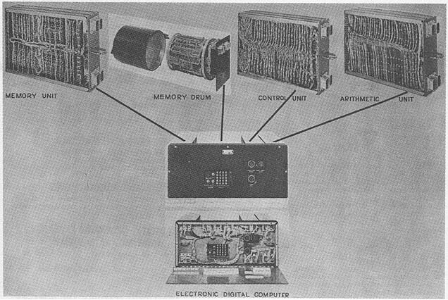
HUGHES LRI X

Hughes LRI X Computer AN/ASG 18

MANUFACTURER
Hughes Aircraft Company
Digital Systems Department

BRL61-0308.jpg
Photo by Hughes Aircraft Company

APPLICATIONS
System is used for real-time computing and control in
complex aircraft systems. Computer includes advanced
displays and extensive analog and digital input-output
capability. In the application for which it was designed,
the computer performs inertial and non-inertial navigation,
weapon control, attack computations, data-link processing,
intercept computations, and automatic tests of over-all
system, for Air Force interceptors. In this application, the
program and input-output are closely integrated with other
electronic and mechanical apparatus in the over-all system.

PROGRAMMING AND NUMERICAL SYSTEM
Internal number system Binary
Binary digits/word 19
Binary digits/instruction 19
Instruction/word 1
Arithmetic system Fixed point
Instruction Modified three address
Number range
-1 to (1 - 2-18)
Instruction word format
+-----------------+---------------+---------------+-----------+
| 9 bits | 5 bits source | 3 bits source | 2 bits |
|relative address | of operand | of operand | func- |
|of next order | No. 1 | No. 2 and | tion |
| | | destination | |
+-----------------+---------------+---------------+-----------+
This structure applies to add, subtract, input,
output, clear and absolute value. Other orders have
slightly different structures.
BRL 1961, HUGHES LRI X, start page 0309


Automatic built-in subroutines include input conversion
(analog, digital, incremental, data link); output
conversion (analog, digital, data link); real time count;
frequency measurement (Independent of program).

Automatic coding includes conversion from simplified
mnemonic code to memory-loading tapes and program
documents, via IBM data processing machinery.

Registers include 4 one-word registers, 3 multiword
circulating registers for fast-access storage, 2 multiword
circulating registers for analog and digital outputs, 3
multiword circulating registers for data link processing,
1 multiword circulating register for frequency count, and
1 multiword circulating register for incremental inputs
and real time count.

The system uses four-phase logic and is normally
programmed in minimum-latency fashion.

ARITHMETIC UNIT
Incl. Stor. Access Excl. Stor. Access
Microsec Microsec
Add 84 84 (3 address code)
Mult variable-84 + 84/bit variable-84 per bit
Div variable-84 + 84/bit variable-84 per bit
Construction (Arithmetic unit only)
Vacuum tubes none
Transistors 810
Arithmetic mode Serial

STORAGE
No. of Access
Media Words Microsec
Magnetic Drum, 40,960 Minimum Latency (normal)
Pre-recorded 84
Maximum possible - 25,000
Magnetic Drum, 1,280 Same
Variable
Magnetic Drum 188 Minimum Latency - 84
Registers Maximum varies 84 to 1,700

INPUT
Media Speed
Voltages (ac and dc)200 microsec/conversion
64 inputs, electronically switched
Pulses (incremental and 5 KC
data link)
On-Off Signals 130 inputs, electronically
switched
Operator Controls (Analog
and Digital)
Frequencies 100 KC
Inputs available to program on demand.

OUTPUT
Media Speed
Voltages (dc) 0.7 sec. full scale slew
On-Off Signals (Toggles)
100 ma., 28 v.
Shaft Positions 80 steps/second
Operator Displays
(Analog and Digital)

CIRCUIT ELEMENTS OF ENTIRE SYSTEM
Type Quantity
Transistors 1,683

CHECKING FEATURES
Checking features include fully automatic self-test
program including marginal test, remotely initiatable,
making use of built-in self-test features. Automatic self-
diagnosis to unit level. Diagnostic program to aid more
detailed diagnosis. External ground-based test equipment
for detailed diagnosis, in conjunction with diagnostic
program.

POWER, SPACE, WEIGHT, AND SITE PREPARATION
Power, computer 0.850 Kw
Volume, computer 2.1 cu ft
Volume, input-output excl displays 1.7 cu ft
Weight, computer 135 lbs
Weight, input-output 50 lbs
Weight, total 185 lbs
System is mounted in aircraft

PERSONNEL REQUIREMENTS
System is designed for operation and maintenance in
unfavorable environments by military personnel with
relatively little training.

RELIABILITY, OPERATING EXPERIENCE,
AND TIME AVAILABILITY
Total system time is approximately 3000 hours to date. Mean-
time-to-failure approximately 150 hours including input-
output.

ADDITIONAL FEATURES AND REMARKS
Outstanding features include semiconductor circuits, very
high maintainability, modified 3-address code designed to
facilitate minimum-latency programing, serial fixed-point
arithmetic, input-output flexibly accessible to program.
 
Last edited:
the AN/ASG-18 proved capable of tracking an Atlas D ballistic missile

My mind was completely blown by this. I was wondering if it could have shot down the Atlas with an AIM-47 Falcon ?
 
Here's the report I never posted before on ASG-18 and GAR 9.

Notes on a Visit to Hughes Aircrrift Co, Culver City, Los Angeles on May 15th and 16th, 1961.

Los Angeles,

Persons seen:-
Mr. W.E. Hinds - Sales
Mr. W. Dickman - Tarran
Mr. E.V. Phillips - C.W. techniques
Mr. R. A. Gehrke - Advanced Fire Control Systems
Dr. H.T. Osaki - Parametric amplifiers

Visitors: - V/c.Cdr . Biggs - Canada
Mr. H. H. Keefe - Canada
Dr. T.S. England
Mr. R. Aspinall
Mr. R.B. Clayton

1. Introduction

Some difficulty arose concerning clearances and there was no technical discussion on the morning of May 15th. The discussion was mainly concerned with the ASG-18 radar and the associated GAR 9 missile. In addition there was some discussion concerning parametric amplifiers.

2. ASG-18

The ASG-18 is an airborne interception radar intended to work in conjunction with the GAR 9 missile. The ASG-18 has the following characteristics
Frequency X band
Transmitter power 3kW mean, 12kW peak
Pulse repetition frequency 250kc/s
Transmitter pulse length 1 usec
Receiver pulse length 2.4 usec
Doppler frequencies searched +- 40 kc/s relative to the Doppler frequency of the carrier aircraft
Aerial search rate 115deg/sec

Transmitter is frequency modulated for ranging with a modulation frequency of 500c/s and a deviation of 500c/s

Additional information not obtained on present visit -
Aerial diameter 40"
Aerial gain 36.9 dB

(1) Aerial Search +-40deg x 4 bars
time for search 3.8 sec
range 100n.m.
Cumulative probability at this range 90%
on a target of speed Mach 5
and echoing area 10 sq m

(2) Alternative scan patterns such that azimuth search is increased to 70deg
and/or number of bars is increased to 8
Conical scan frequency in range 200-400c/s

2.1 Transmitter

The basic frequency is obtained from a temperature controlled crystal oscillator at about 100 Mc/s. The microwave frequency for the transmitter is obtoined by multiplying this frequency by 120 in 2 or 3 stages. The transmitter and local oscillator are phase locked to this source. The bandwidth of the phase locked loop waas thought to be about 200,000 c/s.

The power is then amplified by the travelling wave tubes in series (types HAX 5A and Hax 4). A block diagram is shown in Figure 1. The transmitter power is 3kW mean and 12kW peak and the overall efficiency is 10%. The efficiency of the final stage is 12.5%.

The transmitter specification was such that targets should be visible within 2 kc/s of a large clutter signal. The specification states that the frequency modulation noise in a 250c/s bandwidth shall be less than 75- 80 bB below carrier.

2.2 Duplexer and crystal protection

The aerial has a V.S.W.R. of 1.4 over a 10% band, and thus the peak power returned may be 500 watts.

A gas tube was not incorporated because with this power level it would have had a short life. A ferrite switch was used using a cooled tube of ferrite. This was followed by a low power T.R. tube.
The loss of the ferrite was 0.5 dB. The circulator was liquid cooled and gave 33-38 dB of isolation and a loss of 0.4 dB. It was 4 in. long and the ferrite was attached to the walls. The ferrite was cut into small lengths in order to avoid magnetostriction resonance at the p.r.f. frequency (see fig.2).

When a parametric amplifier was used, noise from the keep alive was observed.

2.3 Receiver

Intermediate frequencies of 30 Mc/s and 1.4 Mc/s are used.

2.4 Clutter rejection

It is arranged that two of the filter banks search in the clutter-free region above the doppler frequency corresponding to the aircraft velocity and the other two filter banks search in the clutter region.

A clutter rejection filter is provided.It is arranged to give 80 dB rejection over a bandwidth of 700 c/s.

Aircraft velocity and position of the aerial dish are used for initial frequency setting of this filter. A frequency lock loop is also provided in order that the frequency of the clutter rejection filter should coincide with that of the main beam return. This loop has a two second memory ( see fig. 3).

The clutter reject filter is provided only in the acquisition mode.

Once locked, the notch filter is removed in order to enable crossing targets to be tracked.

2.5 Multiple filters

The receiver incorporates 4 banks of multiple filters each covering a bandwidth of 20 kc/s.

The filters have the following characteristics:-

Number of filters in a bank40
Bandwidth of filter to 2 dB points500c/s
Centre frequency1.4Mc/s
Insertion loss1.5dB
Type2 crystal lattice
Size of 1 filter1 cu.in.
Long term stability of filter plus detector1 dB
Cost each$130
Change in frequency for 50°c temperature change10-20c/s.


Each filter bank is filter. Each amplifier preceded by is provided an amplifier and a 20 kc/s. wide with separate a.g.c.

A separate frequency control loop, previously described, ensures that the doppler frequency from the main beam return appears between the second and third bank of filters.

With the separate a.g.c. control it will be possible to observe a small target signal in the 3rd and 4th bank and it should be possible to observe simultaneously a larger target signal in the 1st or 2nd bank.

A switch, using Trochotron valves, is used to sample the output of each filter five times in the time that the aerial moves through the target. A dummy filter is provided to give an earthed signal once per switch cycle and enable the levels to be set.

One of the difficulties in the multiple filter bank is the provision of adequate drive power. In order that the detector should be linear it is necessary to have 3V r.m.s. at the detector. For this it is necessary to have a 5V at the input of the filters and thus use a generator giving 20 volts and feed each of them in series with a resistance of 5000 ohms equal to the filter impedance, This means 30 watts is required (see fig. 4 )

Now a number of filters are joined in parallel as shown in figure 5. This has meant that the power consumption has boon reduced. The inductances are incorporated in order to match out the capacitance of the filters when off tune.

A complete filter system has been drawn out but not made. 300 filters plus the switch require a volume of 1800 cu.in.

The Gain stability of the filters is better than 1 dB but at the moment it is effectively 2 dB as non precision resistors are used. One of the variations arises because of magnetisation of the ferrite transformers.

The effect of gain variations of the filters is reduced by the circuit shown in figure 6. The threshold setting is obtained by observing the average noise in the filter before the signal arrives. This gives a slight deterioration of performance, say 1/2 dB.

The sensitivity of the filters is such that there is a 50% probability of detecting a signal having a 4 dB signal to noise ratio when the aerial is scanned at a rate of 115°/sec, This corresponds to a time of 22 m.sec. on the target. There was one false alarm whole filter bank per minute.

Hughes said that the multiple filter system was very trouble free and did not need resetting in a period of a month.

When an alarm is received in one filter an attempt is made to stop the aerial and return it to its original position. This takes 0.1 sec.

The position of the trochotron switch when an alarm was received is used to produce a pseudo signal using a digital oscillator which is applied to the input of the receiver. A fast frequency sweep is used in order to lock on in frequency to this signal (fig. 7),

The position of the switch is altered and the real signal is applied. Velocity lock is then obtained on the real signal.

In order to tell whether a signal is present or not an internal coherency check is used using a jitter oscillator.

The particular method of instrumenting range requires that the signal should be at the centre of the narrow band filter. There is a "lean" of 20 c/s at the output of the discriminator and Hughes have considered the use of a servo system to reduce this to zero.

A phase lock loop is provided in order to ensure that the frequency deviation remains at the centre of the narrowban filter.

One difficulty with the system is that it is necessary to ensure that the frequency deviation produced by the jitter oscillator is small. Otherwise, the measurement of range will be incorrect. In order to avoid this difficulty the system of figure 8 has been adopted. This enables the amplitude of the jitter oscillator to be increased. It was stated that this circuit was working.

It is possible to hold lock on to a slowly accelerating target signal that is 6 or 8 dB below the detection level.

2.6 Angular lock

The operator is presented with a display of azimuth versus velocity with a marker showing the elevation.
A strobe is put on in azimuth and elevation by the operator or by outside information.
If there is an output from the filter at the designated azimuth and elevation, the angular position will be remembered and the aerial will return to this position in O.l sec.

A conical scanning receiver is used for providing angular information.

2.7 Ranging

Range is measured when the aerial is locked on the target.

The p.r.f. is fixed as a subharmonic of the intermediate frequency and so this cannot be varied for ranging.

Range is measured by frequency modulating the transmitter when the aerial is locked. The modulating frequency is 500 c/s and the modulation index equals one.

The phase difference between the frequency modulation on the transmitter and on the receiver is measured. It is thus necessary to ensure that the time delay of any narrow band filter does not vary and this may be very difficult to achieve. There appeared to be no advantage in this method of instrumentation compared to that used by Raytheon in the Hawk system and in fact Hughes are considering the possibility of
having one modulation for acquisition and ranging.

The ranging accuracy is of the order of ½ mile corresponding to 1deg of phase error.

2.8 Aircraft trials

Aircraft trials of pulse doppler radar started in July, 1957.
Some of the equipment has been installed in a T-29 (Convair two engine) aircraft. The mean power was 200 watts and a duty cycle of 1/10 was used.

A single frequency swept filter was used. An attempt was made
to observe the scattering coefficient of the ground and the desert and an attempt was made to lock on to a Canberra target fitted with a Lunberg lens having an echoing area of 600 ft2 , They measured the echoing area of the Canberra and found that it was 80 s q.ft. without the lens and 420 sq. ft. (±_ 2 dB accuracy) wih the lens. However, fading having nulls 40 dB down was observed when the Canberra was equipped with the lens. Hughes could not understand this.

An attempt was made to measure the spectrum returned when flying over the sea and over the desert. No quantitative information was provided.

3. GAR 9

GAR 9 is a missile using a semi-active form of homing and is associated with the ASG 18 airborne interception radar.

Hughes considered the possibility of injecting CW, into the transmitter but rejected this because of weight considerations.

The present missile uses the A.I. transmitter as the transmitter of a semi-active radar and the receiver is incorporated in the missile.

The missile has the following characteristics , -

Weight800 lb.
Receiver dish diameter10-12"
Range at launch30-50 n.m.
Control surfacesmoving tail
Polarisationvertical
Roll control of missile roll rate stabilised

3.1 Progress

A laboratory model has been vibrated and components had been
flight tested.

3.2 Static split receiver

A static split receiver is used.

There are three channels at the intermediate frequency each
incorporating a narrow band filter, whose bandwidth is about twice that of Sparrow. The outputs of these channels are frequency multiplexed to simulate a conical scan system (see fig.9).

There is no increase in bandwidth in the home on jam mode,
The effect of phase changes in the I.F. amplifiers had not been studied.

3.3 Dish system

Various types of aerial have been tried including,(
(1) a dish with four helical feeds to give circular polarisation, this was not actually used.

(2) a dish with four dipole feeds.
and
(3) slot arrays for each of four quadrants in a circle.
A static split receiver is used and there are three mixers and head amplifiers on the dish assembly.

The dish is stabilised using a free gyro and torque motors are used to precess the gyro.

3.4 Reference power

No special reference aerial is usocl on the launching aircraft, so that reliance is placed on the power recieved from sidolobes of the A.I. transmission.

The transmitter pulses of the A.I. radar are received at a reference dish at the rear of the missile. This signal is effectively passed through a narrow band filter.

Care has, of course, to be taken to ensure that the filter is
centred on the fundamental frequency of the original transmission and not separated from it by the pulse repetition frequency.

3.5 Local oscillator

A solid state local oscillator is used giving a power output of 20 m.w. at X band. This signal is derived from a crystal oscillator in the range 50 to 100 Mc/s.


3.6 Receiver

The receiver is turned off when the transmitter pulses are received provided the range from the launching aircraft to the missile is small. At long ranges from the aircraft this gating is removed.

A clock is being considered as giving some estimate of aircraft missile range.

There is no other gating of the received signal.

The receiver is turned off for the first one or two seconds of
flight and an attempt is made to lock on to the target signal. Two accelerometers are provided in order to predict the doppler frequency, and this means that it is necessary to search 10 kc/s. Without accelerometers it is necessary to search 30 kc/s.

4. Parametric amplifiers

Hughes Aircraft Company were doing experimental work on parametric amplifiers and would supply such amplifiers commercially.

Some manufacturers attempt to use 1N 23 cases for holding the varactor diodes but it was considered that the cases are not suitable.

4.1 Quasi degenerate amplifier

The pumping frequency is twice the actual frequency.

If commercial diodes are used with a cut off of 60,000 Mc/s it is possible to obtain a noise factor of 4.5 - 5.5 dB at X band. This includes the circulator loss and the effect of a 10 dB noise factor in the next stage.

The gain of the amplifier is 17 dB and this can be obtained over a bandwidth of 30 to 100 Mc/s.

The amplifier is linear wth a power input between 10-14 and 10-5 watts. These input levels do not deteriorate the noise factor when measured over a broad band. No measurements have been done with a narrow band receiver.

The amplifiers are at present available for sale.

4.2 Non degenerate amplifier

At X band a 3 dB noise factor has been obtained.

Silver bonded diodes are used with a cut off frequency greater than 100,000 Mc/s. The pump frequency is 35,000 Mc/s.

Hughes make these diodes but at the moment they are only getting a yield of 5%. Cooling of the diodes by Peltier cooling gives an improvement in noise factor. An improvement of O.2 dB was obtained with a 20°c difference.

An S band non-degenerate parametric amplifier giving a 5% bandwidth is available for sale. At X band, a quasi-degenerate amplifier gave 5% bandwidth using selected diodes.

4.3 Use in a C.W. receiver

A parametric amplifier has been incorporated in a C.W. system,
It is satisfactory with a spillover power of 60 dB above noise in a 500 c/s bandwidth.

The normal noise factor was 7.5 dB (using a 1N 23F cost $12) and there uas 2.5 dB improvement with the parametric amplifier.

Dual infra-red/radar system

Hughes have done a paper study, but this was not an optimum system.
 
Last edited:
OK, understandable - I'd probably have come to the same decision, if that's what they were like, lol :) I was mostly interested inu figure 4, because I'm having a bit of a hard time picturing what that combined seeker head would look like. The description sounds the IR aperture was somehow also used as the radome.Even today, missiles with such dual seekers (ASM-2, HF-II SSM, ARMIGER project) usually have them separated.
Thomas Brown here. The seeker heads were in the forward chines.
Thomas Brown
35 years at HAC (4 yrs building spare ASG-18 TWTs)
 
Hughes started the development process with uncooled lead sulphide (PbS) detectors in the 2-2.5 micron range, but moved to an argon cooled indium antimonide detector sensitive to longer wavelengths (3-5 microns). The final version fitted to the YB-58 and YF-12 was a nitrogen cooled lead selenide system.
InSb IRSTS development was not occurring yet. It was all PbS or PbSe. I suspect these were the "standard" Hughes PbSe crossed-detector con-scan arrays.

Dual infra-red/radar system

Hughes have done a paper study, but this was not an optimum system.
This is interesting to me, especially considering the proliferation of single IRSTS+FCS integration (slaving & "co-witnessing") AFTER the date of this report. I wonder why the dual-IRSTs were chosen and then rejected. The IR+Radar FCS appears to have been a winner, though.
 
InSb IRSTS development was not occurring yet. It was all PbS or PbSe. I suspect these were the "standard" Hughes PbSe crossed-detector con-scan arrays.


This is interesting to me, especially considering the proliferation of single IRSTS+FCS integration (slaving & "co-witnessing") AFTER the date of this report. I wonder why the dual-IRSTs were chosen and then rejected. The IR+Radar FCS appears to have been a winner, though.
Indium Antimonide was discovered in 1951. InSb missile seekers were absolutely on the way in the late 50s in the UK, entering service in 1964 on Red Top.

I went back to the sources I cited, and in fact Paul Crickmore is vague on timing with the Hughes Indium Antimonide sensor work. Might be early work leading to the Hughes AN/ALR-23 F-14 IRST?

Paul Crickmore - Blackbird, Beyond the Secret Missions.
The effective range of the IR system depended upon the point where either it traversed over the horizon or something appeared between the target and the system. All early IR systems used an uncooled lead sulphide sensor-cell and operated in the short wavelength of 2–2.5 microns. This generated countless discrimination problems, so Hughes continued development work in this field, utilizing the F-102 that Jim Eastham flew out of Holloman AFB, and eventually produced a long wavelength sensor cell using an indium antimide [sic] cell cooled by liquid argon. This worked in the 3–5 micron range and had an outstanding discrimination capability. The IR system installed in the YB-58 and AF-12 was yet another development and it used a lead selenide cell cooled by liquid nitrogen. However, extensive testing of this system would never be carried out.
PbSe and PbTe were very much less sensitive than PbS so constructing long range sensors with them was difficult.
 
Last edited:
Wasn't clear, I was referring to Hughes IRST work.

If I'm reading Hughes After Howard right, the author doesn't mention them messing with InSb in the late 50s. He does mention jumping from PbSe to Ge:Hg, but in the context of FLIR development.

The DSIAC publication The History of Forward-Looking Infrared (FLIR) also calls the F-14's IRST the first major US use of InSb, and heavily implies that the ASG-18 IR systems did not use InSb. But it's also not the most academic of sources.

I find it very difficult to believe that they would have bothered with InSb unless they thought they could get it to work, as it should have been known at the time that there were serious issues with InSb crystal growth methods. Going back to PbSe as a "development" also confuses me. It was well known at the time, having been used in military IR applications since the early '50s.

It's also entirely possible that this development went in the opposite direction. PbS-->PbSe-->InSb. That would explain a common link between ASG-18 and AWG-9+ALR-23
PbSe and PbTe were very much less sensitive than PbS so constructing long range sensors with them was difficult.
Correct. They were still better than PbS for interceptor work due to the spectral response.
 
Hughes IR sensors were created at the Santa Barbara Research Center (https://sbrc-sbrs.com), a separate company owned by Hughes. The history page confirms InSb detectors were first developed for a Hughes IRST, though it doesn't say which one and when.

Mentions are made in the newsletters on this page of the 90C IRST for Air Force and 100C IRST for Navy - not sure I've seen these designations before, but these are known PbS devices.
 

Similar threads

Please donate to support the forum.

Back
Top Bottom