ARL-SM (MiG21Bis)

Slick

ACCESS: Restricted
Joined
14 January 2006
Messages
8
Reaction score
1
This will explain the usage of ARL-SM on MiG21Bis fighter. It is primarily intended for those bought by former Yugoslavia but I guess it will also represent any active Bis on this planet. Stay focused while reading, this was translated on Serbian by military personel, and for this forum is translated again to English by me, so things won't be always in spirit of English language :-X. I haven't checked for spelling errors because my hamburgers will be fried if I don't leave computer right now....


General:

Aparature ARL-SM is used for receiving and decoding commands received from control
centre used for aircraft guidance during mission. Aparature is turned on or off using
"lazur" switch located on the cockpit's right wall. Gudance commands are shown on
navigation and control instruments: UKL-2K, VDI-30, UISM-I and IPL-M. Brightness of
received commands is adjusted using "ark.ipl" situated on cockpit's right wall. Command row
situated on the left cockpit wall can be used for:

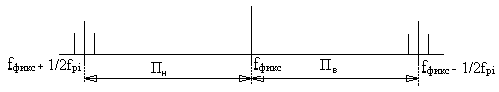
Radio data settings by turning "Volni" (Waves), "Shifr" (Code), "Raznosi" (separation) until
in pits of their protection coverages desired wave values from 10 to 20 are shown in two
rows, for example 1/8 represent the wave number 18.

Pre-settings of radio data and pre-setting signalization, after relevant lights are turned
on when "rucn" button is pressed (after desired Volni, Shifr and Raznosi values are
selected).

Automatic aparature pre-setting on new radio data when "avt" button is pressed, when
cooperation (vzaimodeistvie) command is issued.

adjusting light brightness using "ark" switch.

When ARL-SM aparature is turned on and radio data is selected - lights will signalize that
Volni, Shifr and Raznosi are selected.

Rhytmical blinking of command "I" or some other command on IPL-M will occur when ground
control station is working or when self test (KPA) aparature is turned on.

Course command is issued on UKL-2K related to current course. Fulfillment of course
commands is done by matching the course needle with triangualr index of current course and
during that vertical IPL needle needs to match the vertical line of the cross.

On UISM-I is given the required true airspeed.

Fulfillment of speed commands require that true airspeed needle matches triangular index
of commanded airspeed.

On VDI-30 commanded altitude needed during attack is shown (triangular index related to
altitude scale in thousands (m)).

Altitude commands are fulfilled by matching altimeters short needle with triangular index
of commanded altitude. After commanded altitude is reached horizontal IPL needle matches
horizontal line of the cross.

On IPL following commands can be shown:

<, I, >, F, 100, 60, 36, !, X.

When "<" shines - turn left is being signalized, "I" keep forward, ">" turn right -

informing the pilot about impending maneouver. Turn is being done only after course commands
start changing, adjusting angle of turn so that needle of commanded course is matching with
static UKL index and vertical IPL needle matches the vertical line of the cross.

Shining of "F" command is signal when quickly turning afterburner on is required, and is
followed by rhytmical 800hz sound signal. Once afterburner is on sound signal stops, but
"F" command is still shining. When F stops shining longer rhytmical 800hz sound signal
will appear and represents the command to turn off the afterburner. Once afterburner is off
sound signal stops. Sound commands to turn on or off afterburner are "." or "-" in
Morseus alphabet.

Shining of range command "100", "60", "36" will happen in moment of reaching the given
distance to assigned target and will continue untill next distance command begins to shine.
When "36" command is shining pilot will turn his radar on in search mode.

When distance between MiG21Bis and its target is 20km or smaller - distance info will be
shown on analogue instrument that measures distance.

When "!" signal is shining - it warns the pilot about change of target, or repeated guidance
on the same target. When "!" is on, all other commands will be turned off, and guidance
processing will be ceased as well (speed, altitude and heading will show last issued
values).

When "!" goes off and rhytmical blinking one of "<", ">" "I" will signalize new guidance
commands.

Shining "X" command informs the pilot about guidance interruption. When "X" is on all other
IPL commands will be off. When ground control centre issues "fulfill orders" command - use
given (altitude, speed and course) IPL commands to reach the desired airbase.

Aparature ARL-SM provides semiautomatic transfer on new radio data that are pre-setted while
on ground which is done when "cooperation" command is issued and 800hz uninterrupted
sound signal will appear, shutting down all current commands and interrupting guidance
on target and on ARL-SM command row "avt" (automatic) light is shining. After that new
values regarding Volni, Shifr and Raznosi received from ground control will begin to shine

and sound signal stops. Meanwhile in the pits of protection covers old values will remain.

When one of "<", "I", ">" commands begins to shine rhytmicaly - that signalizes that

transfer to new ground control post is successfuly established and aircraft is receiving

commands from that new control post.

If command about change of target is received by voice via radio than for successful

transfer on new command post it is needed to manually set Volni, Shifr and Raznosi values

and to hit "rucn" (manual) button after that. If one of "<", "I" or ">" commands are shining

rhytmicaly transfer to new command post is successfuly done.

Flight while using ARL-SM:

After placing your ass in the seat make sure that correct Volni, Shifr and Raznosi are

selected.

After getting airborne establish the connection with ground control post and after one of

"<", "I" or ">" begins to shine rhytmicaly relax because your ARL-SM works normally.

After receiving command "Fulfill orders" match your flight on data received from ground

control post.

If "F" appears during guidance - turn the afterburner on and later follow afterburner

commands.

When "36" begins shining turn your radar on in search mode and search for desired target.

When "X" appears stop doing wha are you doing, report to command post and follow the

commands to reach desired airbase.

When flying in group flight leader follows the commands and others are following flight

leader. If leaders ARL-SM malfunctions next flight member with intact ARL-SM becomes flight

leader and informs ground control post about that.

;D
 
Thanks Slick, I have seen only once the BIS cockpit. It happened on the airshow in Hungary, there was one serbian Mig-21bis, but I do not remember the LAZUR panel and it is also missing on my cockpit photos. Is it possible that the LAZUR panel could have been removed because of modernization? Is this panel you were talking about?
lazur.jpg

and the BIS from Kecskemet05.
img_5269.jpg
 
Hi there :),

This on the picture is Bis from Deltas (note blue triangle under monster's head ;)) based in Belgrade (Batajnica). Can't say I ever looked well inside them because Fulcrums were around too and are much more interesting.

The panel from your picture generally looks like thing we are speaking about. If you haven't found anything like that, maybe you haven't searched hard enough or maybe it was removed. If you remember from acig.org I told you info is from "Izmene & dopune" which means ARL-SM isn't in the regular manual anymore. One Bis pilot said he has only handful of successful intercepts using ARL-SM. The biggest problem was that operator had no idea has his command went through or not, so we soon begun using radio together with ARL-SM. Now pilot had to watch displays and to focus on using radio as well. If either pilot or guy in command post were late in something or confused for a few moments it may disturb the planned pattern and whole thing looked clumsy.

Also during seventies we have tried to make SAMs and Fishbeds working with Swedish STRIL60, one our Bis has radar display removed and camera monitor and controls in place of it, some still remember red face of US military advisor when he saw we have turned some of their precious Sabre Dogs into recon planes...

I also have some procedures for ground control guy, but I have problem translating a few abbrevations and typing mathematic formulas in this fonts. If we overcome this you'll see that on this forum too...

Cheers ;D
 
Dear Slick, do you know exactly what was the data rate and the transmission pattern from a Vozdukh ground station to the ARL-SM Lazur on board the MiG-21? Was the transmission continuous, or in short bursts of data? How reliable the system was in practice?
 
The Lazur radio link is an element of the Vozdukh integrated system and ensures the transmission of commands from a ground point and their automatic reception on fighter aircraft with display on visual indicators and flight instruments.

Guidance commands can be transmitted over the Azure radio link, setting the fighter's course, altitude, speed, turns, as well as indicating the relative position of the target and the distance to it, or instead of guidance commands, interaction commands that give the fighter data for a new radio link setting: wave number, spacing number , cipher number.

The equipment of the radio link “Lazur” consists of ground and aircraft equipment.


Ground equipment includes :

a) a device for picking up commands from the PSA;

b) remote PU;

c) an encryption device that converts commands into electrical signals;

d) control devices.


Aircraft equipment includes :

a) a radio receiver;

b) control panel;

c) command decoder;

d) rectifier;

e) block of magnetic amplifiers (MU);

f) a system of indicators.


The main feature of the radio link "Lazur" is the principle of constructing its high-frequency channel, which is as follows.

Radio transmitting devices emit two rigidly interconnected frequencies. The difference between these frequencies remains practically unchanged. The value of this difference (frequency spacing) is used as a specific tuning parameter for the Lazur radio link.

Both carrier frequencies are in-phase modulated in amplitude by the tonal frequencies of the control channel signals. Control commands are allocated and sent to indicator devices.

For the operation of the radio link "Lazur" a range of 100 - 150 MHz is used, within which 118 fixed waves can be used. On each fixed wave, 8 high-frequency channels can be used, which differ from each other in the amount of separation between them, i.e. carriers.

Up to three groups of fighters can be directed simultaneously on each high-frequency channel. To separate the commands transmitted for different groups, time selection is used: signals are transmitted in successive cycles, which differ from each other in the call ciphers of the groups (first to the aircraft of the first group, then the second and third).

The range of the radio link "Lazur" at H - 10000 m is 350 km.

Radio link "Lazur" can issue:​

  • 128 course commands within 0 - 360 0 with an error of ± 6 0 ;​
  • 126 altitude commands within 500 - 30000 m with an error of ± 300 m;​
  • 32 speed commands within 500 - 2400 km / h with an error of ± 70 km / h;​
  • 3 turn commands: "left", "straight", "right";​
  • 3 targeting commands: "left", "straight", "right";​
  • 4 range commands to the target: "20 km", "10 km", "5 km", "Hang up";​
  • 1 team "Glow";​
  • 1 command "End guidance";​
  • 20 commands "Wave number";​
  • 8 commands "Spacing number";​
  • 3 commands "Cipher number".​

Interaction of ARL blocks and cascades according to the functional diagram


The ARL functional diagram reflects the operation of the main blocks and includes:​

  • high-frequency receiver (2LAS - 21);​
  • low-frequency receiver (2LAS - 22);​
  • decoder (2LAS - 3);​
  • block of magnetic amplifiers (2LAS - 414);​
  • ARL control panel (2LAS - 23);​
  • flight and navigation instruments: VDI - 30, KUSI, UKL, IPL.​


The impact of ARL units and cascades according to the functional diagram will be considered in two sub-questions:

a) operation of the receiving part of the ARL;

b) the work of the decoder.


The work of the receiving part of the ARL


The conversion of the received 12-pulse sending of guidance commands is carried out by blocks 2LAS - 21, 2LAS - 22.

The 2LAS - 23 numbers of the wave, cipher, spacing set on the 2LAS - 23 control panel provide, through the tuning mechanism, the adjustment of the UHF oscillatory circuits, the 1st mixer, the 2nd mixer, the 1st local oscillator, the 2nd local oscillator of the 2LAS - 21 receiver to obtain a constant value of the intermediate frequency (ƒ pr \u003d 3333.3 kHz) at the output of the RF PRM.

The HF signals of the guidance commands at the next two frequencies are received by the antenna and enter the UHF, the bandwidth of which is determined (you can ask a problematic question, what determines the UHF bandwidth?) The maximum separation frequency

ƒ p8 = 416 kHz

Amplified high-frequency signals, under the action of ƒ r1 and ƒ r2 in the 1st and 2nd mixers, are converted to ƒ pr \u003d 3333.3 kHz, which is amplified by the amplifier and then fed into the LF PRM 2LAS - 22.

ƒ pr = (ƒ hf i - ƒ g 1i ) - ƒ g 2i = 3333.3 kHz, where i = 1..20

In
htmlconvd-3zsLoP_html_bd32dd5b296646.png
the LF PRM, the signal is divided into the upper subcarrier frequency (ƒ in ) and the lower (ƒ n ), by adjusting the input oscillatory circuits of the amplifiers ƒ in and ƒ n having a bandwidth (P in , P n ).

The amplified signals ƒ in and ƒ n enter the mixers ƒ in and ƒ n , where under the action of ƒ g 2LAS - 22 they are converted into intermediate frequencies ƒ Vpr and ƒ Npr .

ƒ Vpr \ u003d ƒ in - ƒ g \u003d 1175 kHz \u003d const

ƒ Npr \u003d ƒ n - ƒ g \u003d 1175 kHz \u003d const

Changing the frequency of the local oscillator LF PRM is carried out on the control panel 2LAS - 23 by switching the value of the spacing number (ƒ pi ).

This explains the constancy of the values of ƒ Vpr and ƒ Npr.

htmlconvd-3zsLoP_html_5c425b99e6725be4.png
Intermediate frequencies are amplified in the IF ƒ in and ƒ n and fed into the difference frequency mixer, at the output of which we already have a single 12-pulse message, a carrier frequency of 171 kHz, while maintaining amplitude modulation with frequencies F i . The difference amplifier provides amplification ƒ of the difference frequency to the amplitude necessary for efficient operation of the detector, which detects the signal and thus exclusively the carrier frequency of 171 kHz.

At the output of the detector, we have 12 video pulses with amplitude modulation by frequencies F i .

Thus, signals of modulation frequencies carrying information of control commands are selected in the detector. After amplification, the voltage of the modulation frequencies enters the decoder, where messages are selected according to the cipher number and the signals of the modulation frequencies are converted into a voltage that provides a display of the commands transmitted from the PN, i.e., the received messages are decoded.


Decoder operation


The encoded control command, which is a code combination of modulation frequency signals, is fed to the selection circuit according to the call cipher. This circuit consists of low-pass filters tuned to modulation frequencies (F 1 = 110 Hz, F 2 = 150 Hz, F 3 = 190 Hz, F 4 = 235 Hz, F 5 = 290 Hz) and five relay stages. When receiving the signals of the calling cipher, the circuit generates a starting pulse.

This impulse enters the start-stop mechanism of the switchgear, which is a lamella along which the brushes rotate. The rotation of the brushes comes from the engine, which starts to rotate from the moment the equipment is turned on, but until the start pulse arrives, the distributor brushes stand still. At the moment of arrival of the starting impulse, the motor shaft engages with the brush shaft (through the friction clutch) - the brushes begin to rotate. When the brushes rotate, they pass through all the working lamellas that serve to prepare the relays. After one complete revolution, the brushes stop in their original position. A new cycle of movement of the brushes along the lamellas begins only after the next arrival of the start pulse, i.e. after the command of the cipher corresponding to the one installed in the decoder. The cipher selection scheme also works in the second mode in the mode - the mode of converting a quaternary code to binary. In the second mode, the circuit automatically switches after decoding the cipher determined by the first three sendings of commands. When operating in the second mode, the quaternary command code is converted into binary and the binary code combinations are separated into schemes of the first and second code lines. Commands of the course and spacing number are sent to the scheme of the first code line, and commands of the command of altitude, speed, turn, target designation, number of the cipher wave are sent to the scheme of the second code line. Code combination schemes are a set of relays that convert binary command code combinations (set relays) and store these code combinations (memory relays reproduce the transmitted set of commands).

The contacts of the memory relays of the heading, speed and altitude commands switch the resistances included in the bridge circuits of the tracking systems of the heading, speed and altitude indicators located in the magnetic amplifier unit. The memory relay of the turn and target designation commands energizes the corresponding signal lamps of the light board. Reception of range commands to the target is carried out by a special range command relay at the moment the brush of the fifth distributor lamella passes. At the same time, voltages are supplied through the relay contacts to the signal lamps for the range of the light panel. When receiving interaction commands, a supply voltage is supplied through the relay to the corresponding signal lights of the control panel. Simultaneously with the processing of the received interaction commands, a voltage with a frequency of 800 Hz is applied to the launcher - a sound signal in the pilot's headset.


The principle of constructing code commands


Control commands are transmitted over the radio link in successive cycles. Each command transmission cycle takes 1.2 and consists of 12 code packets sequentially transmitted in time, which differ in filling frequencies. Five modulation frequencies are used to fill code packages: F 1 = 110 Hz, F 2 = 150 Hz, F 3 = 190 Hz, F 4 = 235 Hz, F 5 = 280 Hz.

The structure of the command transmission cycle is shown in Fig. 1. In each cycle, the first three messages are used to convert the code combination of the calling cipher of the object's fighter groups. Table 1 shows combinations of three calling ciphers adopted for groups 1, 2, 3.


Call cipher​
Fill frequency​
First premise​
Second premise​
Third premise​
First group​
F1 _​
F4 _​
F1 _​
Second group​
F1 _​
F5 _​
F1 _​
third group​
F1 _​
F2 _​
F1 _​


Table 1.


A characteristic feature of the code combinations of calling ciphers is that each of them begins and ends with a message = 110 Hz.


slats​
one​
2​
3​
four​
5​
6​
7​
eight​
9​
ten​
eleven​
12​
1st code line​
Call cipher​
Team selection​
Range​
←―Course—→​
2nd code line​
Call cipher​
Team selection​
Range​
←——―Speed———→
←―Height—→←―CU—→​


Rice. one​

In this case, the frequency = 110 Hz is not used in other code combinations of the cipher. In each cycle, one of the five following sets of commands can be sent:


  1. set: heading, altitude, altitude and range commands;​
  2. set: heading, speed, turn and range commands;​
  3. set: course, speed, target designation and range commands;​
  4. set: "end pointing" command;​
  5. set: interaction commands "wave number", "split number", "cipher number".​


To form a code combination that determines which of the five possible sets of commands is transmitted in a given cycle, the fourth and fifth parcels are used.

Table 2 shows the code combinations adopted to determine the set of commands transmitted in this frame.


Set name​
Commands included in the set​
Modulation fill frequencies​
fourth premise​
fifth parcel​
the first​
K - V - D​
F4 _​
Defined by range command value​
second​
K - S - R - D​
F3 _​
third​
K - S - C (I) - D​
F2 _​
fourth​
interaction commands​
F5 _​
F3 _​
fifth​
end pointing​
F5 _​
F5 _​

Table 2.


In the first, second and third sets of commands, the following modulation frequencies are used to transmit the range command (see Table 3).​


Meaning of range commands​
Modulation frequency of filling the fifth parcel​
twenty​
F5 _​
ten​
F4 _​
5​
F2 _​
lights out​
F3 _​

Table 3


The last seven messages of each cycle are used to form code combinations corresponding to the values of the remaining commands transmitted in this cycle. Each of the parcels can be filled with any of the four modulation frequencies: F 2 , F 3 , F 4 , F 5 .


To explain the principle by which the transmission of different sets of commands is carried out, consider the case of the transmission of the first set of commands, i.e. simultaneous transmission of heading command and altitude command.

128 heading command values and 126 altitude command values can be transmitted over the Lazur radio link.

To transmit course commands, a binary seven-bit code is used. This code allows you to get 128 different combinations.

Indeed, characterizing each parcel with one of two signs (for example, "1" and "0"), you can:​

  • using one package to get two combinations;​
  • using three parcels to get 2 3 = 8 combinations;​
  • using seven parcels to get 2 7 = 128 combinations.​
Exactly the same binary code (seven bits) for transmitting 126 different values of the height command (2 values are not used). The structure of the code combination corresponding to one of the 128 course values is shown in fig.​

6​
7​
eight​
9​
ten​
eleven​
12​
0​
one​
0​
one​
one​
one​
0​
The task of simultaneously transmitting heading and altitude commands is reduced to the need to transmit two combinations of the form:

Well:​

6​
7​
eight​
9​
ten​
eleven​
12​
one​
0​
0​
one​
0​
one​
one​
Heights:​

6​
7​
eight​
9​
ten​
eleven​
12​
0​
one​
0​
one​
one​
one​
0​
or what, too, with one combination of the form:​

one​
0​
0​
one​
0​
one​
one​
0​
one​
0​
one​
one​
one​
0​


in which each premise is characterized not by one of two, but by one of four signs:​

one​
,​
one​
,​
0​
,​
0​
.​
one​
0​
one​
0​
Each of these four features corresponds to one of the four modulation frequencies as shown in the table.​

one​
0​
0​
one​
0​
0​
one​
one​
F2 _​
F3 _​
F4 _​
F5 _​
Then for the previous figures the code combination will correspond:

Heading and Altitude:​

one​
0​
0​
one​
0​
one​
one​
0​
one​
0​
one​
one​
one​
0​
F2 _​
F4 _​
F3 _​
F5 _​
F4 _​
F5 _​
F2 _​
Thus, the simultaneous transmission of two binary codewords is equivalent to the transmission of one quaternary codeword. The validity of this can be verified by performing the following calculations. The number of all possible combinations of a binary seven-digit code is 2 7 = 128.

Therefore, the total number of different options that can be obtained by combining all possible combinations of such a code in pairs with each other will be equal to 128 2 . 128 \u003d 2 7 * 2 7 \ u003d 4 7 , i.e. the same number using a seven-digit quaternary code.

In the future, we will assume that course commands are transmitted in binary code combinations on the first (upper) line, and altitude commands or instead of them, speed and target designation commands are transmitted in binary code combinations on the second (lower) line.

On fig. examples of cycles of various structures are shown:​

one​
2​
3​
four​
5​
6​
7​
eight​
9​
ten​
eleven​
12​
F1 _​
F4 _​
F1 _​
F4 _​
F5 _​
F3 _​
F5 _​
F4 _​
F3 _​
F3 _​
F4 _​
F3 _​
1st group​
1st set​
20 km​
F1 _​
F2 _​
F1 _​
F2 _​
F2 _​
F2 _​
F4 _​
F3 _​
F4 _​
F4 _​
F4 _​
F3 _​
3rd group​
3rd set​
5 km​


In this case, when in the next cycle the second set (heading, speed, turn, range) or the third set (heading, speed, target designation, range) is transmitted, the heading command is transmitted along the first line, and the speed and turn command or the speed and target designation command on the second.

For the transmission of 32 speed commands, 5 parcels are used (from 6 to 10 inclusive), and for the transmission of target designation (channel) or turn commands, two parcels (11 and 12) are used.

In the last figure, the structure of the cycle when transmitting commands to aircraft of the third group: D = 5 km, K = 180, C = 800 km/h, the target is on the left.

In the case when the “End guidance” command is transmitted in the next cycle, the modulation frequencies of the bursts from 6 to 12 inclusive are indifferent, since the decoder of the commands of the “Lazur” radio link is designed in such a way that when during the fourth and fifth bursts of the cycle the frequencies pass sequentially F 5 and F 5 , then the signal “End of guidance” is immediately processed.


F1 _​
F4 _​
F1 _​
F5 _​
F5 _​
F3 _​
F5 _​
F4 _​
F3 _​
F3 _​
F4 _​
F3 _​
1st group​
end pointing​
If an interaction command is transmitted, then the “split number” command is transmitted on the first line, and “wave number” and “cipher number” are transmitted on the second line.​

Spacing number​
Parcel coloring on the 1st line​
6​
7​
eight​
9​
ten​
eleven​
12​
one
:
eight​
Spacing​
cipher​
Wave number​
Coloring the parcel on the 2nd line​
6​
7​
eight​
9​
ten​
eleven​
12​
one
:
twenty​


When pointing one, two or three groups of fighters, a certain order of alternation of cycles with different sets of commands is automatically provided.


Indicator devices of the radio link "Lazur"


Commands for pointing the radio link "Lazur" are issued to the following devices:​

  1. UKL - heading indicator designed to indicate the compass course of the aircraft flight, the magnetic bearing of radio stations (MPR) and heading angles of radio stations (KUR), as well as to indicate the set flight course of the aircraft and issue signals of deviation from the set course.​
  2. VDI - 30 - altimeter (indicator), designed to indicate the barometric and specified altitude of the aircraft flight (range of measured altitudes up to 30,000 m).​
  3. UISMI (or KUSI) - an indicator of the true airspeed and M number (indicator) designed to indicate the true and set airspeed, as well as to indicate the M number (range of measured speeds up to 2500 km / h).​
  4. IPL is a pilot indicator (zero indicator) with a light panel, designed to indicate the difference between the given values \u200b\u200bof the heading and flight altitude and the true values, as well as to indicate turn commands, target designation, range to the target and the “end of guidance” command. The block of magnetic amplifiers (MU) is a device that interconnects the elements of tracking systems located in indicator devices and in the decoder. It contains the MU tracking systems of the course, altitude, speed and the tracking system of the null indicator. In indicator devices, commands are issued using servo microdrives, made on the principle of automatically balanced bridges. The diagonals of the bridges include MUs that amplify and convert mismatch signals. The voltage corresponding to the compass heading is generated on the GIK-1 compass potentiometer, amplified and converted by a standard amplifier and processed by the servo drive, which is in UKL. The angle equal to the compass heading (Kk) is worked out on the course scale by the pointer (aircraft silhouette).​
From the decoder through the MU of the heading tracking system, the voltage proportional to the given heading enters the tracking system, which works out the given heading (Kz). At the same time, the difference Kz - Kk with UKL is fed to the input of the "zero indicator". The difference is counted according to the position of the vertical arrow (horizontal scale).

The altitude indicator indicates the barometric flight altitude (Nb) (small arrow KM, large M). The voltage proportional to the given height (Hc) from the decoder through the MU is fed to the input of the tracking system VCH - 30. After working out, Hc is counted relative to the moving index. From DV - 30, a voltage proportional to Nb is supplied to the MU. The same MU receives a voltage from the decoder proportional to Hc.

The difference Nz - Nb in the form of voltage is fed to the input of the tracking system IPL. This difference is measured by the position of the horizontal line (vertical scale).

The indication of the flight speed is carried out by applying a voltage proportional to the set speed Uz from the decoder to the input of the speed tracking system and subsequent processing of this voltage by the KUSI tracking system. Uz is counted on a scale relative to the moving index.

One-time commands are displayed on special signal boards of the IPL device (turn, target designation, range, end of guidance).

On the front panel of the PU there are 17 buttons for switching waves, spacing and ciphers (respectively 6, 8, 3).

The lighting of the indicated bulbs, which is accompanied by a signal in the phones, indicates the passage of interaction commands. Light bulbs light up from a signal from the decoder. To execute the interaction command, the pilot must press the buttons near the lights that light up.

After typing the appropriate interaction command, it is necessary to press the release button available on the control panel, after which the indicator lights go out and guidance continues on the new control channel.​
 

Similar threads

Back
Top Bottom