- Joined
- 27 December 2005
- Messages
- 16,415
- Reaction score
- 18,967
Su-27SK Datalink Info
Operation of equipment for receiving guidance commands and active response 11G6.
On-board equipment is designed to receive control commands transmitted from the point of guidance and transmission of flight information at ranges of up to 400 km in direct visibility when operating 11G6.
The equipment provides:
radio visualization of aircraft and the transmission of flight information (on-board number, remaining fuel, Nbar and one-time messages from A-511 via the return channel of the Raduga-SAZO-SPK-75 radio line) through a 6202P-1 transmitting device;
reception of guidance and control commands transmitted from guidance points on command radio control lines (KRU) Lazur-M, Biryuza, Raduga-SPK-68 and Raduga-SAZO-SPK-75.
The equipment has four operating modes, in each of which it works on fixed radio data (RD) that are operatively tunable in flight. The SAZO sighting channel operates on one fixed wave.
The equipment provides for automatic transition to new radio data in all modes when receiving the “Interaction” command transmitted from the joint venture, as well as manual switching from the control panel and control equipment 11G6.
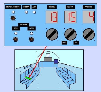
Management and control of the work are carried out from the control panel, on the front panel of which the following controls and displays are located:
TRANSIT END button, for issuing on the PN messages about the steady passage of commands on new radio data;
lamp TRANSITION END to indicate to the pilot the issue of this command to the pilot.
On the plane, a button and a lamp OVER not involved.
KONTR lamp - to control the passage of commands from the PN and check the operability of the product. When receiving commands with PN, it should burn 1.5; 3.0 or 4.5 seconds in the Lazur-M mode and 5.0; 10.0 or 20.0 seconds in the "Biryuza", SPK-68 and SPK-75 modes, depending on the rate of issuing commands from the payload with short-term extinction for a time of ~ 0.2 sec.
Upon termination of communication with the PN, the KONTR lamp should go out after 15 seconds or 30 seconds, depending on the presence of a tempo sign in the control commands;
AVT lamp - to indicate reception of the INTERACTION command, according to which the equipment is automatically tuned to new radio data and the operating mode. With a steady reception of aircraft control commands on new radio data, the AVT lamp goes out;
buttons and lamps ALM and SPK - to check the indicators of the remote control, select the operating mode of the equipment and indicate the selected mode.
When ALM and SEC buttons are pressed simultaneously with the ЗК-СИФР-АЗС switch in the CIPHER position, all signal lamps should light up, and the numbers 88, 88 and 8, which should blink at a rate of 0.8 1.2 sec
At. briefly pressing the ALM button for 1.5-2.0 seconds, the equipment switches to the "Lazur-M" or "Biryuza" modes; when the SPK button is pressed - in the SPK-68 or SPK-75 modes (depending on the position of the Cipher switch), the corresponding lamp - ALM or SPK - lights up.
When signals are received through the sighting channel (SAZO), the lamp of the on mode blinks.
ZK-SHIFR-AZS switch on 20 provisions divided into three sectors:
in the ЗК sector - 3 positions - for setting the set number (1, 2 or 3) of the request code (ЗК) of the sighting channel. To enter the request code, it is necessary to set the specified ЗК number on the indicator using the switch in the ЗК sector, while the WAVE and DIVISION indicators should go out and briefly press the operating mode button - SEC or ALM for 1.5-2 sec. During pressing, the digital indicator should display the same number as before pressing. After entering the ZK, set the switch in the Cipher sector;
in the Ciphering Sector there are 15 provisions for setting the specified cipher number and operating mode.
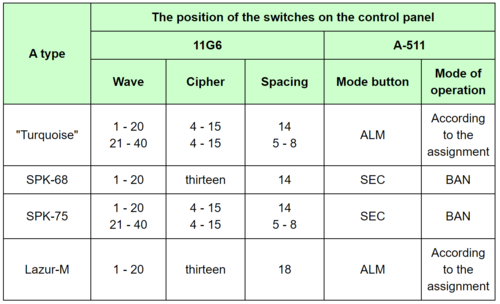
Ciphers 1-3 are used in the "Lazur-M" and SPK-68 modes.
Ciphers 4-15 are used in the "Biryuza" and SPK-75 modes.
In the Lazur-M and Turquoise modes, the cipher plays the role of the address of the aircraft to which the information issued from the payload is intended.
in the AZS sector, there are 2 positions for turning on the indication of the side number of the aircraft in the SPK-68 and SPK-75 modes. In either of the two positions on the Wave, Cipher and Spacing indicators, the number set on the A-511 aircraft responder dialing device is displayed with a blinking light.
WARNING. When setting the ZK-SHIFR-AZS switch to the AZS position, it is forbidden to press the SPK and ALM buttons.
WAVE switch for 20 positions, for selecting a working wave, the value of which also depends on the position of the DIFFERENCE switch;
WAVE indicator, to indicate the number of the installed wave from 1 to 40;
Spacing switch for 8 positions and an indicator for setting spacings in the Lazur-M mode and wave numbers in other modes (1-20 or 21-40).
In "Lazur-M" mode, for each wave number set by the WAVE switch from 1 to 20, all 8 spacings are used to configure the radio receiver. In the “Biryuza”, SPK-68 and SPK-75 modes, for setting waves from 1 to 20, set the DIFFERENCE switch to positions 1-4, and waves from 21 to 40 to positions 5-8.
To turn on the 11G6 equipment, turn on the ON / OFF switch on the power panel. At the same time, the ALM or SEC lamp and all digital indicators light up when setting the ZK-SHIFR-AZS switch in the SHIFR sector. Allowed short-term, no more than 6 seconds, blinking mode lamp and short-term lamp illumination CONTROL - no more than 5 seconds.
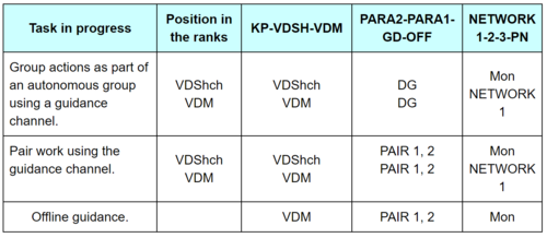
To receive guidance commands on the switchgear "Lazur" and "Biryuza", the K-DlAE complex receiver is used, while the switch of the NETWORK 1-2-3-PN exchange networks should be in the PN position.
Guidance equipment is integrated with transponders A-511 and 6202P-1. To turn on the transponders, turn on the ON / OFF switch on the power panel and set the A-511 operating mode switch to the BAN position.
Preparation of equipment for the flight and the actions of the pilot:
set the appropriate number on the dialer A-511 and check it;
set the specified number of the request code and the channel of sight;
to set the WAVE, Cipher, DIVISION switches with working radio data;
briefly press, for 1-2 seconds, the button for the operating mode of the SEC or ALM;
set the controls on the control panels A-511 and K-DLAE in accordance with the selected operating mode 11G6.
The positions of the switches on the control panels of the equipment 11G6, A-511, K-DlAE, depending on the specified operating mode, are shown in tables 1 and 2.
Remote control and monitoring equipment 11G6.
The automatic adjustment of the equipment to new radio data transmitted from the PN is carried out by the “Interaction” command, while the AVT lamp lights up and a continuous sound signal with a frequency of 1000 Hz is heard in the headphones. When switching to new radio data, the WAVE, Cipher, and SPACE indicators will show new radio data. When receiving control commands on new radio data, the ABT lamp goes out and the sound signal stops.
WARNING. After changing the radio data manually, press the button for the corresponding ALM or SEC mode.
When the ALM or SEC button is pressed while the AVT lamp is on, the equipment switches to the old radio data and the sound signal stops.
When the “Afterburner” command is received, the signal Ф is displayed on the HUD and an intermittent sound signal is heard in the headphones with an interruption frequency of 10 Hz. When the pilot performs the "Afterburner" command, the sound signal stops.
When the “Afterburner” command is removed from the PN, the indication of the signal Ф is stopped on the HUD and an intermittent sound signal is heard in the headphones with an interruption frequency of 1 Hz. After the pilot completes this command, the sound signal stops.
Note:
1. The guidance mode is implemented only for one group.
2. In the group guidance mode, only the leading group is guided.
3. Guidance in the group is performed only when the network switch is set to NETWORK 1.
The output from 11G6 equipment is displayed on the SEI “Narcissus” (HUD)
Tactical information is displayed on the IPV: (HUD)
Symbols of your aircraft and goals transferred from NASU;
their relative position in space;
flight characteristics of the target: flight direction, speed and altitude;
deviation from a given course.
On the ILS, the aircraft and sighting command are displayed:
symbols KN, BN or BP - ways of entering into combat contact with a target (SVBS) - command guidance; airborne guidance or airborne search;
PPS or ZPS - a sign of the hemisphere of attack of the target (front or rear);
ELZ - recommendation for the inclusion of radar radiation;
F - the command to enable afterburner;
B - vertical - a command to perform a maneuver in a vertical plane;
! - retargeting;
T - drive;
OTV ֶ ← → - command to perform maneuver in the horizontal plane;
О - guidance mark, the deviation of which is proportional to ∆Ψ = Ψtek - Ψ back;
Nzad - the value of the altitude of the target or the height of the interceptor during barrage or drive;
Vset - the value of the true flight speed;
VL - approach speed of the interceptor with the target;
L is the slant range from the interceptor to the target;
Etc and βc are the azimuth and elevation angle of the target, according to which the center of the radar zone or OEPS is set, in the form of a deviation of the mark of the center of the zone.
The set course is displayed on the PNP when the AUTO - MANUAL DIRECTION switch on the PZ-188 is in the AUT position.
When this switch is set to the MANUAL position, the set course is set by the rack on the PNP.
When stopping the passage of commands (the CONTROL lamp stops flashing), you must:
check the compliance of the position of the controls 11G6 set for flight
switchgear mode and the correspondence of the switchgear operating modes and equipment A-511 and K-DlAE (tables 1 and 2);
request flight data from the RP (operating mode, radio data, ZK number and on-board number);
check the operability of 11G6 equipment, for which press the GUIDANCE button on the ground control panel. During normal operation, the CONTROL lamp should light up with a brief extinction at a rate of 0.8-1.5 seconds and the following information should be displayed on the HUD:
Ψset = 28 ° - guidance mark on the right;
Vset = 360 km / h;
Nzad = 2360 (2620) m;
Lset = 8 km in SPK-68 mode, 9-9.5 km in Lazur-M mode and 32 km in Biryuza and SPK-75 modes.
In case of a faulty SAZO channel, the CONTROL lamp should be lit continuously, with a faulty RPU of the Lazur-M and Biryuza modes — blink briefly at a speed of 0.8-1.6 seconds, and with a faulty monoblock, the lamp should not light.
Operation of equipment for receiving guidance commands and active response 11G6.
On-board equipment is designed to receive control commands transmitted from the point of guidance and transmission of flight information at ranges of up to 400 km in direct visibility when operating 11G6.
The equipment provides:
radio visualization of aircraft and the transmission of flight information (on-board number, remaining fuel, Nbar and one-time messages from A-511 via the return channel of the Raduga-SAZO-SPK-75 radio line) through a 6202P-1 transmitting device;
reception of guidance and control commands transmitted from guidance points on command radio control lines (KRU) Lazur-M, Biryuza, Raduga-SPK-68 and Raduga-SAZO-SPK-75.
The equipment has four operating modes, in each of which it works on fixed radio data (RD) that are operatively tunable in flight. The SAZO sighting channel operates on one fixed wave.
The equipment provides for automatic transition to new radio data in all modes when receiving the “Interaction” command transmitted from the joint venture, as well as manual switching from the control panel and control equipment 11G6.
Management and control of the work are carried out from the control panel, on the front panel of which the following controls and displays are located:
TRANSIT END button, for issuing on the PN messages about the steady passage of commands on new radio data;
lamp TRANSITION END to indicate to the pilot the issue of this command to the pilot.
On the plane, a button and a lamp OVER not involved.
KONTR lamp - to control the passage of commands from the PN and check the operability of the product. When receiving commands with PN, it should burn 1.5; 3.0 or 4.5 seconds in the Lazur-M mode and 5.0; 10.0 or 20.0 seconds in the "Biryuza", SPK-68 and SPK-75 modes, depending on the rate of issuing commands from the payload with short-term extinction for a time of ~ 0.2 sec.
Upon termination of communication with the PN, the KONTR lamp should go out after 15 seconds or 30 seconds, depending on the presence of a tempo sign in the control commands;
AVT lamp - to indicate reception of the INTERACTION command, according to which the equipment is automatically tuned to new radio data and the operating mode. With a steady reception of aircraft control commands on new radio data, the AVT lamp goes out;
buttons and lamps ALM and SPK - to check the indicators of the remote control, select the operating mode of the equipment and indicate the selected mode.
When ALM and SEC buttons are pressed simultaneously with the ЗК-СИФР-АЗС switch in the CIPHER position, all signal lamps should light up, and the numbers 88, 88 and 8, which should blink at a rate of 0.8 1.2 sec
At. briefly pressing the ALM button for 1.5-2.0 seconds, the equipment switches to the "Lazur-M" or "Biryuza" modes; when the SPK button is pressed - in the SPK-68 or SPK-75 modes (depending on the position of the Cipher switch), the corresponding lamp - ALM or SPK - lights up.
When signals are received through the sighting channel (SAZO), the lamp of the on mode blinks.
ZK-SHIFR-AZS switch on 20 provisions divided into three sectors:
in the ЗК sector - 3 positions - for setting the set number (1, 2 or 3) of the request code (ЗК) of the sighting channel. To enter the request code, it is necessary to set the specified ЗК number on the indicator using the switch in the ЗК sector, while the WAVE and DIVISION indicators should go out and briefly press the operating mode button - SEC or ALM for 1.5-2 sec. During pressing, the digital indicator should display the same number as before pressing. After entering the ZK, set the switch in the Cipher sector;
in the Ciphering Sector there are 15 provisions for setting the specified cipher number and operating mode.
Ciphers 1-3 are used in the "Lazur-M" and SPK-68 modes.
Ciphers 4-15 are used in the "Biryuza" and SPK-75 modes.
In the Lazur-M and Turquoise modes, the cipher plays the role of the address of the aircraft to which the information issued from the payload is intended.
in the AZS sector, there are 2 positions for turning on the indication of the side number of the aircraft in the SPK-68 and SPK-75 modes. In either of the two positions on the Wave, Cipher and Spacing indicators, the number set on the A-511 aircraft responder dialing device is displayed with a blinking light.
WARNING. When setting the ZK-SHIFR-AZS switch to the AZS position, it is forbidden to press the SPK and ALM buttons.
WAVE switch for 20 positions, for selecting a working wave, the value of which also depends on the position of the DIFFERENCE switch;
WAVE indicator, to indicate the number of the installed wave from 1 to 40;
Spacing switch for 8 positions and an indicator for setting spacings in the Lazur-M mode and wave numbers in other modes (1-20 or 21-40).
In "Lazur-M" mode, for each wave number set by the WAVE switch from 1 to 20, all 8 spacings are used to configure the radio receiver. In the “Biryuza”, SPK-68 and SPK-75 modes, for setting waves from 1 to 20, set the DIFFERENCE switch to positions 1-4, and waves from 21 to 40 to positions 5-8.
To turn on the 11G6 equipment, turn on the ON / OFF switch on the power panel. At the same time, the ALM or SEC lamp and all digital indicators light up when setting the ZK-SHIFR-AZS switch in the SHIFR sector. Allowed short-term, no more than 6 seconds, blinking mode lamp and short-term lamp illumination CONTROL - no more than 5 seconds.
To receive guidance commands on the switchgear "Lazur" and "Biryuza", the K-DlAE complex receiver is used, while the switch of the NETWORK 1-2-3-PN exchange networks should be in the PN position.
Guidance equipment is integrated with transponders A-511 and 6202P-1. To turn on the transponders, turn on the ON / OFF switch on the power panel and set the A-511 operating mode switch to the BAN position.
Preparation of equipment for the flight and the actions of the pilot:
set the appropriate number on the dialer A-511 and check it;
set the specified number of the request code and the channel of sight;
to set the WAVE, Cipher, DIVISION switches with working radio data;
briefly press, for 1-2 seconds, the button for the operating mode of the SEC or ALM;
set the controls on the control panels A-511 and K-DLAE in accordance with the selected operating mode 11G6.
The positions of the switches on the control panels of the equipment 11G6, A-511, K-DlAE, depending on the specified operating mode, are shown in tables 1 and 2.
Remote control and monitoring equipment 11G6.
The automatic adjustment of the equipment to new radio data transmitted from the PN is carried out by the “Interaction” command, while the AVT lamp lights up and a continuous sound signal with a frequency of 1000 Hz is heard in the headphones. When switching to new radio data, the WAVE, Cipher, and SPACE indicators will show new radio data. When receiving control commands on new radio data, the ABT lamp goes out and the sound signal stops.
WARNING. After changing the radio data manually, press the button for the corresponding ALM or SEC mode.
When the ALM or SEC button is pressed while the AVT lamp is on, the equipment switches to the old radio data and the sound signal stops.
When the “Afterburner” command is received, the signal Ф is displayed on the HUD and an intermittent sound signal is heard in the headphones with an interruption frequency of 10 Hz. When the pilot performs the "Afterburner" command, the sound signal stops.
When the “Afterburner” command is removed from the PN, the indication of the signal Ф is stopped on the HUD and an intermittent sound signal is heard in the headphones with an interruption frequency of 1 Hz. After the pilot completes this command, the sound signal stops.
Note:
1. The guidance mode is implemented only for one group.
2. In the group guidance mode, only the leading group is guided.
3. Guidance in the group is performed only when the network switch is set to NETWORK 1.
The output from 11G6 equipment is displayed on the SEI “Narcissus” (HUD)
Tactical information is displayed on the IPV: (HUD)
Symbols of your aircraft and goals transferred from NASU;
their relative position in space;
flight characteristics of the target: flight direction, speed and altitude;
deviation from a given course.
On the ILS, the aircraft and sighting command are displayed:
symbols KN, BN or BP - ways of entering into combat contact with a target (SVBS) - command guidance; airborne guidance or airborne search;
PPS or ZPS - a sign of the hemisphere of attack of the target (front or rear);
ELZ - recommendation for the inclusion of radar radiation;
F - the command to enable afterburner;
B - vertical - a command to perform a maneuver in a vertical plane;
! - retargeting;
T - drive;
OTV ֶ ← → - command to perform maneuver in the horizontal plane;
О - guidance mark, the deviation of which is proportional to ∆Ψ = Ψtek - Ψ back;
Nzad - the value of the altitude of the target or the height of the interceptor during barrage or drive;
Vset - the value of the true flight speed;
VL - approach speed of the interceptor with the target;
L is the slant range from the interceptor to the target;
Etc and βc are the azimuth and elevation angle of the target, according to which the center of the radar zone or OEPS is set, in the form of a deviation of the mark of the center of the zone.
The set course is displayed on the PNP when the AUTO - MANUAL DIRECTION switch on the PZ-188 is in the AUT position.
When this switch is set to the MANUAL position, the set course is set by the rack on the PNP.
When stopping the passage of commands (the CONTROL lamp stops flashing), you must:
check the compliance of the position of the controls 11G6 set for flight
switchgear mode and the correspondence of the switchgear operating modes and equipment A-511 and K-DlAE (tables 1 and 2);
request flight data from the RP (operating mode, radio data, ZK number and on-board number);
check the operability of 11G6 equipment, for which press the GUIDANCE button on the ground control panel. During normal operation, the CONTROL lamp should light up with a brief extinction at a rate of 0.8-1.5 seconds and the following information should be displayed on the HUD:
Ψset = 28 ° - guidance mark on the right;
Vset = 360 km / h;
Nzad = 2360 (2620) m;
Lset = 8 km in SPK-68 mode, 9-9.5 km in Lazur-M mode and 32 km in Biryuza and SPK-75 modes.
In case of a faulty SAZO channel, the CONTROL lamp should be lit continuously, with a faulty RPU of the Lazur-M and Biryuza modes — blink briefly at a speed of 0.8-1.6 seconds, and with a faulty monoblock, the lamp should not light.