MiG-25P Weapons system

overscan (PaulMM)

Administrator
Staff member
Joined
27 December 2005
Messages
16,454
Reaction score
19,153
Chapter I

GENERAL CHARACTERISTICS

The weapon system of the MiG-25P aircraft is part of the aviation-missile complex of interception, providing, together with other systems of the complex, the defeat of enemy air targets (aircraft and air-to-ground missiles) day and night in any weather conditions and in organized interference at the onboard guidance stage.

The weapon system includes the following units and systems:

  • combat means - all-angle K-40R air-to-air missiles with a semi-active radar homing head PARG-12VV (RGS) or all-angle K-40T missiles of the same class with a thermal homing head (TGS):
  • four aircraft launchers APU-84-46, designed for suspension, launch and emergency drop of missiles, as well as for supplying missiles with compressed air and cooling missile compartments with freon on the ground and in joint flight in the air while preparing them for launch;
  • an electrical weapon control system with automation units designed to power missiles on a suspension, signaling, control circuits and automatic preparation and launch of missiles;
  • red dot sight KIO-T for aiming at visually visible targets.

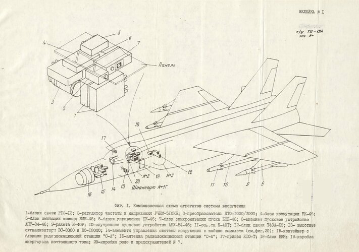
The layout diagram of the weapons system units is shown in Fig. 1

Fig1.jpg

The composition of the air-missile interception complex, except for the weapons system. includes:
- guidance system "Vozdukh-1M";
- interceptor aircraft (carrier);
- radio control system S-A;
- state identification system;
- Polet-1I navigation and landing system. which includes the automatic control system SAU-155P.

The guidance system is used to detect air targets, generate signals and commands that provide guidance to the interceptor aircraft on the target, and transmit these signals to the aircraft.

The radio control system is designed to detect and auto-track air targets, as well as to generate and issue the necessary signals and commands to ensure aircraft control at the stage of onboard guidance and aimed missile launch.

The identification system is designed to determine the nationality of targets.

The navigation and landing system is used to generate signals and commands necessary for automated flight control at the stages of cross-country flight at seven intermediate bait points, return to the airfield and landing approach.
The automatic control system SAU-155P is designed for automatic and semi-automatic (director) control of the aircraft at the stages of dash and on-board guidance, cross-country flight, return to the airfield and for landing.

The aircraft's armament system is interfaced with the SA radio control system, VS-8000 and VS-18000 high-altitude signaling devices, SKV-2N-2 and D1-1A sensors, as well as with the system for automatic (counter) starting of aircraft engines. Interaction with other systems of the complex (airborne ARLS-M, SAU-155P, etc.) is carried out by interfacing the S-A radio control system with them.

A simplified block diagram of the interfacing of the weapon system with the systems of the air-missile interception system is given in Fig. 2. The equipment of all the above systems works together.

The complex provides an attack on a collision course at altitudes of 2500-27000 m at target speeds of 1000 to 3000-3250 km / h and an attack along the rear hemisphere at altitudes of 800-27000 m at target speeds of 800-2300 km / h - depending on the flight altitude.

The interceptor's missile weapon is used in the form of four symmetrically located launchers (suspensions) under the wing. On the left and right wing consoles, two launchers APU-84-46 are mounted from below at distances of 3381.5 mm (internal) and 4577 mm (external) from the plane of symmetry of the aircraft. ALU fastening - pivot.

Rockets are hung on launchers. The longitudinal axes of the missiles are inclined downward at an angle of minus 1°54' 47" with respect to the horizontal of the fuselage, and the centers of gravity of the missiles are separated from the wing chord: external - by 770 mm, internal - by 780 mm.

In relation to the plane of symmetry of the aircraft for launchers - missiles, the following numbering is adopted, if viewed in the direction of flight:
  1. outer on the left wing console;
  2. inner on the left wing console;
  3. inner on the right wing console;
  4. outer on the right wing console.
The missile armament of the aircraft ensures the defeat of air targets - from small-sized cruise missiles of the Hound-Dog type to large strategic bombers.
The following missile suspension options are possible:
  • two missiles with RGS and two missiles with TGS (standard version);
  • four missiles of the same type of RGS
Notes.
  1. With a mixed version, missiles with thermal homing heads are suspended on internal launchers.
  2. A different number of rockets, except for four, is not allowed to be suspended.
The presence of suspended missiles is indicated by signal lamps on the light panel of the dashboard. APU-84-46 starting devices are complex electromechanical units. Each launcher is a beam - a pylon with two pairs of guides 1200 mm long each at the bottom and two cones of pins at the top for attachment to the wing. Inside the beams are mounted:

  • a locking mechanism for fixing a suspended rocket - in each launcher;
  • signaling and blocking mechanism - in each starting device;
  • a docking and tear-off mechanism for connecting electrical circuits and a pipeline to a launcher, a device to a rocket - in each launcher;
  • a pneumatic system consisting of compressed air cylinders, gearboxes and pneumatic electrovalves for supplying missiles during preparation for launch and tactical launch - common for external and internal starting devices of each wing console;
  • an emergency release pneumatic system, consisting of an emergency compressed air cylinder, a pneumo-electric cockpit and pneumatic pushers that provide emergency overgrowth of the rocket - in each launcher;
  • a cooling system consisting of freon cylinders, a filter, a freon level sensor, etc., which serves to cool the rocket compartments during flight - in the launcher;
  • coaxial-waveguide transition (CS) - for transmitting HF radar to a missile - in each launcher.
  • rockets with their skids (yokes) are suspended on the guides of the launchers and, using a docking-tear-off mechanism, are joined to the launcher via electrical circuits, an air system and a freon cooling system.

For details on the starter, see Chapter IV.

Electrical weapon control system coupled with the system radio control S-A, is described in detail in chapters V and VI

Missile launch circuits for blocking the cleaning of the nose landing gear and the relay for disconnecting powerful consumers, as well as a safety check in each ALU-84-46.

The number of missiles launched, i.e. launch option, set by the switch "One - Series 2" (in the cockpit). The launch of missiles is carried out by the pilot by pressing the combat button on the aircraft control stick. The control and launch control system provides with each press of the combat button: - launch of a full missile; - launch of two missiles in a series with a time interval of 0.6 + - 0.08 sec. The system also provides emergency release of missiles in pairs or four at once, which is performed by pressing the "Emergency release SS" push switch (in the cockpit).

The process of intercepting an air target during the operation of the complex in the Vozdukh-1M guidance system includes the following steps:
  • ground-guided interceptor;
  • on-board guidance of the interceptor, during which it is carried out according to the target;
  • return to the airport of departure; approach and landing.
The ground (long-range) guidance station is intended for: launching the interceptor into a region of space relative to the target, from which it is possible to carry out a subsequent attack on the target; target detection and acquisition by airborne radar; preparation of the weapon system for combat work.

[to be continued]
 
Last edited:
The following airborne systems are involved in the ground guidance phase:
  • aircraft radio link equipment ARLS-M;
  • automatic control system SAU-155P;
  • weapon system.
The ground guidance stage begins after takeoff when the interceptor approaches the initial guidance point, at the moment the ACS is switched on to the "guidance" mode.

Aircraft control at the ground guidance stage is carried out by the pilot according to the director signals (pointers) of command and navigation devices, which respond to commands from the Vozdukh-1M system (via the automatic radio link ARLS-M).

  1. At the stage of ground guidance, when retracting the landing gear after takeoff, when there is no line on the launchers of at least one missile, the PTO 1000/3000 converter is launched and after 5 seconds, the "Glow I" command is issued to the launch automation units and to the missiles, according to which:

    I) the gyroscopes of the thermal and radar heads of the missiles are untwisted;

    2) the filament circuits of the klystron of the radar heads of the missiles are powered;

    3) a system of coarse, and then fine tuning of the pulse repetition rate begins to work in the RGS.

    In 2 minutes after issuing the command, the specified equipment is completely ready for operation.
Detection and acquisition of an onboard radar target is ensured by turning on the radiation of the radar at a certain distance to the target automatically or manually (by the pilot), searching for a target in a given area of space (in the forward hemisphere), ♦ detecting the target, identifying it on the radar screen and capturing the target by pressing the button " Capture".

The preparation of the weapon system for combat work is ensured as soon as the command "Nakal" received from the ARLS-M equipment, or after the radiation of the onboard radar is turned on, the calculating device of the S-A equipment forms the command "Nakal II". In the weapon system, part of the circuits of the launch system and the rocket are included. The control is carried out by the light bulb "H" on the frame of the radar indicator (see Fig. 3), the aircraft is controlled by the directory mark of the UKPO.

After the pilot presses the "Capture" button, the radar captures the target in terms of angle and range, and 1.5 seconds after that, the SRP issues the "Attack" command to the ACS. The control is carried out by the light bulb "A" on the frame of the radar indicator.

The airborne guidance stage is intended for: launching the interceptor into a region of space relative to the target, from which it is possible to hit the target with missiles; target attacks and missile launches; provide a way out of the attack.

The following onboard systems are involved in the onboard guidance stage;
  • C-A radio control system, consisting mainly of a radar station (RLS) and a computing device (CHI) associated with an automatic control system;
  • automatic control system for aircraft SAU-155P;
  • weapon system

The airborne guidance stage begins from the moment the radar target is captured and the S-A radio control equipment switches to auto-tracking mode, when the computing device issues the “Attack” command to the ACS. On command "Attack" the interceptor is controlled in the lateral channel according to the given crown calculated by the SRP, in the longitudinal channel the height is stabilized by the ACS.

When the range equal to "D Hill" is reached, CHI enters the command "Hill" into the ACS (control is made by the light bulb "G" on the frame of the GLS indicator). From that moment on, the control of the aircraft in the longitudinal and transverse channels is carried out according to a given course and a given overload, calculated by a calculating device. The aircraft is controlled according to the director's marks of the UKPS.

Radio control equipment 0-A, operating in conjunction with other systems, provides at the onboard guidance stage:
  • withdrawal of the carrier aircraft to the zone of possible missile launches;
  • determination of the boundaries of the launch zone, preparation of missile control equipment for launch and issuance of permission to launch missiles;
  • irradiation of the target during launch and after the launch of missiles with CGS until the launched missile meets the target;
  • no way out of the attack;
  • transition to ground guidance mode.

The S-A radio control equipment ensures the launch of missiles during an attack both in the rear hemisphere of the target and on a collision course. Due to the reduction in the range of the radar station when operating near the earth's surface, the attack of targets in the altitude range of 500-5000 m is carried out by the complex only in the rear hemisphere of the target.

All four missiles are being prepared for launch simultaneously.

The development of commands for preparation, aiming and launch is provided by system radio controls and weapons in the following sequence.

The final preparation for the launch of missiles is carried out by two groups of teams:

- commands to turn on the missile equipment (in accordance with the time schedule); about
- commands for setting up missile equipment before their launch.

The first group includes the "Incandescent II" commands and the "Preparation" command, after which the rocket becomes completely ready for launch in 6-8 seconds (if the signal reflected from the target is sufficient in power).

Commands of the second group "H1", "H2" (two launch altitude commands - more than 8000 m and more than 18000 m) are used to correct the amplification coefficients of the circuit in the rocket autopilot depending on the launch conditions and to set the amplification coefficient of the homing circuit and the delay time of the fuse.

The "Nakal 1" command can be issued automatically from the ground guidance system or manually when the radar radiation is turned on. At this command, the rest of the filament circuits are powered, the nitrogen supply of the TGS heat exchanger is turned on, the gyroscopes of the autopilot of the missiles are untwisted, the high voltage of the klystron and CGS is turned on, the target designation of the radar at the corners for missiles with TGS is worked out for up to 4.5 seconds. The signal lamp "1" lights up on the frame of the radar indicator.

The time to enter the mode by command "Nakal 1" does not exceed 30 seconds.
The "Prepare" command is given approximately 10 seconds before the start-up zones are reached. On this command, the final preparation of the electrical circuits of the weapon system takes place, air is released into the homing heads of the missiles. Heads work out radar target designation and, subject to testing angles and the presence of a signal of the required power, the target is captured.

For RGS, the capture of a target corresponds to the "Capture" command issued from the head to the weapon system. For TGS, the fact of capture is determined indirectly by the fact that the head does not leave the target designation zone by angle for a certain time.

In the event of a radar failure, the "Prepare" command can be issued manually.

When piloting the interceptor in accordance with the law of aiming (attack curve), at the same time, the C-A radio control system generates and outputs to the weapon control system the relevant necessary information and one-time commands and polls the readiness of the missiles.

When the range to the target is less than or equal to the maximum allowed launch range and the target bearing angle is less than 45°, the calculating device issues the command “Range allowed".

The command "Range allowed" is a block in the chain of commands "Launch enabled" and in case of failure of the radar can be issued manually by the switch for entering the preparation command "PP-ZP" (position "ZP").'

The procedure for interrogating the readiness of missiles and issuing the "Start" command to ready missiles for all launch options is as follows: rocket No. 2, rocket No. 4, rocket no. 3, rocket no. 1.

Missile launch permission commands are generated by the missile preparation and launch automation system: the "Launch is allowed" command is issued by communication units in the presence of the commands "Range allowed" • and "Capture" of the head (if the target indicated by the radar is firmly captured by the missile's homing head).
At the same time, the signal lamp "2", "4'', "3"; or "1" of the authorized launch of the corresponding missile lights up on the frame of the radar indicator.

In the event of a failure of the entire C-A radio control system, the preparation of missiles for launch and their launch can be carried out manually by the pilot in the “f-0” mode. in case of CHI failure - in "'Ìa" mode.

Missiles are launched by pressing the combat button.

When you press the combat button in the automation of missile control, the "Start" command is issued. On this command, the lock of the locking mechanism of the launcher is unlocked, and the power unit is launched in the rocket and the autopilot of the rocket is checked. If the autopilot is in good condition, determined by the arrival of the rocket "On the rudders", and there is a signal to open the lock of the starting device, it starts the engine and the tracer of the rocket. A rocket is being launched.

From the moment the rocket power unit is launched, the corresponding suspension signaling lamp on the dashboard display starts flashing, informing the pilot about the launch process. ,

The “Start” command until the rocket leaves the guide launchers is blocked and is not removed even when the combat button is released. When the combat button is pressed again, the second missile is launched in accordance with the procedure for polling readiness and launch restrictions.

After the launch of the rocket (missiles), the electrical circuits of the pntanp LP7 are de-energized with voltages P5v, Zvv, 27v and the corresponding alarm lamps go out two in the cockpit ("CO inside, left, etc.), as well as signaling lamps for the permitted launch on the frame of the radar indicator ("2", "4", etc.).

The target of unprepared or faulty missiles is excluded by a system of blocking the launch automation equipment (control units).
 
ROCKETS K-40P , K-40T

The K-40R missiles with a semi-active radar homing head and the K-40T missile with a thermal homing head are designed to destroy air targets day and night in simple and difficult meteorological conditions in the entire operational speed range and at all aircraft flight altitudes, taking into account restrictions set in the pilot's manual.

Both missiles - cruise - are made according to the aerodynamic scheme "Canard". Wings and rudders are located separately in two mutually perpendicular planes.

The layout of the rocket is made in the form of a set of separate completed compartments.

Depending on the modification, a radar head (RGS) or a thermal homing head (TGS) is installed in the head of the rocket.

Both heads are independent compartments, ending in a nose fairing, consistent with the overall shape of the rocket. Electrical and mechanical docking of RGS and TGS with the rocket ensures their complete interchangeability.

The semi-active radar head PARG-12VV for direction finding uses the energy of electromagnetic waves reflected from the target, irradiated by the radar station of the carrier aircraft accompanying the target. The signal received by the antenna head from the target is amplified by the receiver, detected, decomposed. through the control channels and enters the pneumatic device for rotating the antenna. When the target deviates from the equisignal line, this device turns the antenna in the direction of the target, which is how the homing head tracks the target. A signal proportional to the absolute angular velocity of the target is sent to the autopilot to control the angular velocity of the missile using the rudders. Thus, the missile is guided to the meeting point with the target using the method of proportional approach.

The head has a device that provides an attack on the active jammer.

The thermal homing head is an optical-gyroscopic two-channel tracking system with power stabilization of the position of the optical axis in space, designed for continuous tracking of the direction of the radar antenna of the carrier aircraft, automatic self-tracking of the selected target and issuance (in accordance with the adopted control law) in I missile control equipment signals proportional to the angular velocity of the line of sight of the target.

For direction finding, the thermal energy of the target is used, captured by a special photoresistor.

Behind the head, in a separate steering compartment, there is a pneumatic system for powering the gyro stabilizer drives, consisting of
a high-pressure cylinder, a start pyrocrane, a charging valve and a two-stage pressure reducer (for CGS). To cool the photoresistor TGS, gaseous nitrogen is used at -160°C.

But on the sides of the cylinder there are two autopilot steering machines, powered by powder gases, to control the rocket along the pitch and course channels.

In the upper part of the compartment there is a block for locking the rudders, pneumatic freon and electrical connectors for docking with the corresponding connectors of the starting device.

In the lower part of the compartment, on a horizontal board, there are air and gas inlets of communications connecting the rocket compartments. On the same board there are electrical connectors that connect the tear-off connector with the electrical connectors of the rocket components, as well as the emergency rudder locking pyrocrane and the air release valve from the . cylinder into the homing head through the gearbox.

Four rudders are installed on the power frame of the compartment, connected to the steering servos using special shafts and levers, which ensure the deviation of the rudders at the maximum stroke of the steering servo by 20 °.

A combined radio-optical fuse, also made in the form of an independent compartment, is attached to the rear end of the compartment using a flange joint.

The fuse consists of autonomous optical and radar parts. The part of the fuse occupied by the optical channel has windows spaced around the perimeter, covered with heat-resistant optical glass.

Between the air tank of the steering compartment and the front end of the combined fuse, a filter block is installed, which is a matching device between various head options and the autopilot.

Behind the combined radio-optical fuse is an autopilot that stabilizes the flight of the rocket and controls the rocket in two channels, as well as stabilizes the position of the rocket along the roll.

A gunpowder jet engine is placed between the autopilot and the tail section. On the engine compartment there are missile suspension units and a fairing for communication communications of the nose and tail compartments. Two exhaust nozzles are screwed into the rear cover of the engine. Behind the engine is the warhead.

In the tail compartment there is an autopilot steering machine for controlling the ailerons, an integrated turbogenerator power unit, as well as a cooling connector and plug-in electrical connectors for connecting the power unit with the rest of the rocket units. A safety actuator (PIM) is also located in the tail compartment. The safety-actuating mechanism detonates the warhead when a signal is given from the fuse and has three stages of protection that guarantee safety when handling the missile.

In the tail section of the rocket there is a receiving antenna of the radar channel of the combined fuse and a tracer.

Outside, at the bottom of the rocket, starting from its tail section and including the front compartment, there is a chute that contains: the waveguide of the aft antenna of the radar homing head, the coaxial cable of the receiving antenna of the combined fuse, as well as air and gas pipes and electrical communications.
 
BRIEF INFORMATION ABOUT RADIO CONTROL EQUIPMENT S-A JOINT OPERATION OF ROCKETS WITH EQUIPMENT
MANAGEMENT

The S-A radio control equipment installed on the aircraft, which includes the Smerch-A radar station, the Smerch-AB counting device and the interface unit, is designed to work together with the weapon system, on-board equipment ARLS-M (Lazur -M"), the Bronze interrogator, the SR0-2M transponder and the SAU-155P aircraft control system.

Radio control equipment operating as part of the complex in conjunction with other systems provides:
- search and detection of air targets in the forward hemisphere of the carrier aircraft when it is guided using the ARLS-M equipment by the Vozdukh-1M ground system (automatic control mode) or during semi-autonomous aircraft actions (semi-automatic or director control mode);
- automatic capture and auto-tracking of the target;
- the launch of the carrier aircraft at the stage of onboard guidance to the zone is possible:: launches;
- determination of the boundaries of the launch zone, preparation of missile control equipment for launch and issuance of permission to launch missiles;
- irradiation of the target during launch and after launch of missiles with PIT! before the meeting of the launched rocket with the target;
- exit from the attack;
- transition to ground guidance mode.

The main operations for controlling the S-A equipment are carried out by the pilot using the controls located in blocks 19, 19A, 19H of the radar and the "Capture" button located on the aircraft control stick about

The S-A radio control equipment works in conjunction with the weapon system in the modes of review, capture, tracking and interference. In survey mode, the radar searches for a target automatically or manually. The indication ek1>a-on in these modes is shown in Fig. 3 (pos. A and B).

During operation of the radar station with K-40R missiles, after the target is detected by the radar station and locked in angle and range, the aircraft is controlled in the horizontal and vertical planes according to the signals issued from the CHI.

When the interceptor reaches the estimated range of preparing missiles for launch, the SIG generates and issues the “Preparation” command to the “weapon system”. On this command, air is supplied to the RGS for the pneumatic unloading of the coordinator, which is brought to the bearing of the target with a "phasing pulse" from the radar.

At the end of the distance working out in the PIC rangefinder, from there the command "ZFI" is issued to capture the phasing pulse, according to which the head of the PARG-12VV rocket is transferred to the "tracking" of the probing pulse. At the same time, the carrier frequency auto-tuning system in the CGS tunes the klystron resonator according to the probing pulse, which comes from the radar via the RF signal. cable Through KVP. At the end of the carrier frequency adjustment, the RGS issues the command "ZZI" to the communication unit - capturing the probing pulse.

When coordinating the direction of the coordinators of the homing heads and the radar antenna in the communication unit RBS-12, the command "Confirmation zone" is generated, according to which the homing heads switch to capturing the pulse reflected from the target. Inside the confirmation zone, the homing heads autonomously track the target, outside the zone, the homing heads are turned off and brought to the radar bearing.

After checking the reliability of tracking the pulse reflected from the target, the pilot gives permission to lock the target by pressing the "Capture" button on the control stick. With the mouth, the target is captured and the equipment: the radio control switches to auto-tracking mode. The screen display in Capture mode is shown in FIG. 3 (pos. B).

If there is a signal from the radar "Drazr." and the "Capture" signal, the communication unit issues the "Start allowed" command, which is indicated on the frame of the radar indicator by the green lights "1", "2", "3", "4" of the allowed launch.

Upon receipt of the command "Start permitted" and the closing of the combat button "Start" on the aircraft control stick, the command "Start" is formed in the blocks of automatic preparation and launch of missiles.

The power unit is launched in the rocket and the rudders are unlocked. As soon as the power unit. enters the mode, the command "On the rudders" is issued to the launch system, according to which the rocket engine is started and it leaves the launcher rails.
From the moment the rocket’s power unit was launched, the lights “SSin..”SS external…” start flashing on the light panel in the cockpit, informing the pilot about the launch process.

2 seconds after pressing the combat button in the blocks of automatic preparation for the launch of missiles, the "De-energize" command is formed, which removes * all the power supply to the rocket from the tear-off connector.

After the rocket leaves the rails during its flight, the fuse is cocked. The missile warhead detonation system is ready for operation.
If no meeting with the target occurs within the set time after the missile launches, the missile self-destructs.

In the event of active interference on the main channel, after range capture, the interference indication circuit is triggered and the additional channel is turned on. If there is no interference during the transition to an additional channel, and the target is not captured (due to a lack of potential at long ranges), then the SN is automatically changed to information about the range to the target and the speed of approach to it according to the signals earth. After the range capture occurs, information about the range to the target and the speed of approach to the target will again come from the radar rangefinder.

If interference also appears during operation on an additional channel, then the radar rangefinder switches to target tracking according to the memorized speed of approach of the target and the interceptor.

Three times there is active interference, the command "Interference OK" is issued to the missile in the main channel. The communication unit switches the missile head into the mode of tracking interference along the angle and issues a "Capture" signal to the aircraft.
In this case, the autoselector frequency is not pre-tuned by the phasing pulse. When the interference disappears, the missile head switches to the search mode. "The target pulse at a distance using a phasing pulse.
 
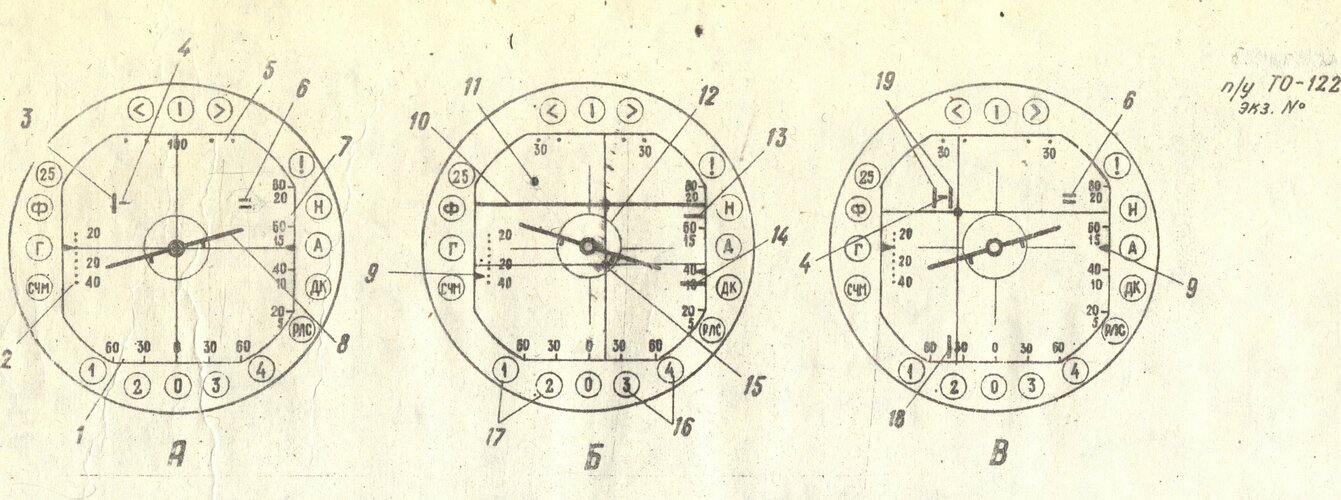
Fig. 3. Indication on the radar screen when operating in various modes

Smerch-A Display.jpg

A - Automatic guidance (review) mode

1. scale of the viewing area (search) in azimuth;
2. pitch angle scale;
3. mark of the position of the center of the search area in azimuth and range (strobe);
4. target mark;
5. scale of the search area in azimuth;
6. identification mark (above the target mark);
7. range scale;
8. current roll indicator

B - Capture and auto-track mode

9. pitch angle indicator;
10. identification mark;
11. radar antenna beam position mark;
12. ring limit (permitted) angles, launch for missiles with CGS;
13. mark of the current range to the target;
14. mark of the maximum allowed launch range "Dr max.";
15. command and flight mark node (UKPO);
16. signaling lamps for the permitted launch of missiles No. 3 and 4;
17. lamps signaling the permitted launch of missiles 1 and 2

V. Manual guidance mode

1. point of purpose;
5 . scale of the search area in azimuth;
6. identification mark
9. pitch indicator;
18. mark of the position of the center of the search area in azimuth (before gating);
19. capture zone marks (strobes).
 
Source documents:

Aircraft MiG-25P. Technical description. Book II. Armament (1972)

"Aircraft MiG-25P. Technical description. Book V: Electronic equipment (1972).

What software package do I use to open these files after downloading them? They clearly aren't PDFs.
 
There's a command line version for Mac here:

Many Mac archivers can decompress 7-zip. Try googling it.

e.g.:
 
Are there any additional details about 40T seeker? How exactly all-aspect was achieved? And am I reading it right and it was dual band?..
 
Not dual band, no, it mentions a dual channel tracking system.

It doesn't say what material the photoresistor was made from but most likely it was PbS (Lead Sulphide). It is nitrogen-cooled, which with Lead Suphide would give limited all aspect capability, especially against supersonic targets which were the MiG-25's mission.

It could be Lead Selenide (PbSe) or even Indium Antimonide (InSb) in theory and both would be better. Both had been used in the UK on Red Top prior to the R-40 entering service.

However we know the USSR had nitrogen-cooled PbS seekers in this timeframe - R-13M's Iney-70 seeker for example, so unless we have a counter-example, I would assume it was PbS.
 
Last edited:
Yeah, PbS is most likely. It was used for many years after in domestic missiles anyways. Albeit InSb isn't impossible too since it got its place in different applications at a time, even if not in missile seekers.
 
Do we know anything about the maneuvering capabilities of the R-40? Perhaps 25G similarly to the R-24?
 
MiG-25P FOXBAT A Flight and Combat Employment Training Manual (in English) has a lot of interesting stuff. I OCRed it so the text can be copied and pasted for discussion.

LINK

Source:
 
The armament system of the МiG-25P interceptor-fighter is intended to hit air targets, primarily high-altitude and high speed targets, both in daylight and at night and VFR and IFR conditions when performing rear-cone and forward-cone attacks as well as high aspect angle-off attacks. The aircraft armament system incorporates the following;
  1. airborne radar RP-25
  2. four air-to-air missiles of the R-40 type
  3. missile launching system;
  4. K-10T collimating sight.
The aircraft may employ the following organic versions of
external stores:
  1. two missiles provided with infra-red homing heads (inner)
    and two missiles equipped with radar homing heads (outer);
  2. four missiles fitted with radar homing heads.
    The R-40 missiles provided with infra-red homing heads are
    not to be used from the outer launchers due to great errors in
    target indicating by the homing heads.
AIRBORNE RADAR RP-25

1. PURPOSE AND BASIC PERFORMANCE OF RP-25 RADAR

The RP-25 radar is intended to ensure air target interception and makes it possible to solve the following main missions:
  1. air target search and detection;
  2. target identification in joint operation with theSRZO-2 interrogator-responder;
  3. target lock-on and its automatic tracking with respect to the angular coordinates and range;
  4. issue of commands into the automatic control system;
  5. furnishing of signals and commands required at the stages of the interceptor-fighter-to-target approach, aiming, and missile launching;
  6. shaping and generation of signals of missile launch preparation, launch clearance, illumination of a target when launching the missiles provided with radar homing heads;
  7. indication of the moment and direction of break-off.
The air target detection range at detection probability of 0.5 with effective reflecting surface and equivalent reflecting surface of the B-52 aircraft at high altitudes accounts for 90 km.

Air target lock-on range (target of the B-52 aircraft type) with the detection probability of 0.9 at high altitudes amounts to 60 km.

The scanning zone, with the aircraft radar operating in the automatic control mode, is as follows:
  • 30° in azimuth with the possibility of smooth automatic displacement through _+55°;
  • 11.6° in elevation with the possibility of smooth automatic displacement upward from 0 to 10°.
With the airborne radar operating in the manual control mode, the scanning zone in azimuth accounts for 60° with the possibility of discrete displacement through +40°. The scanning zone in elevation accounts for 11.6° with the possibility of discrete displacement upward through 30° and downward by 10° (in the LOW ALTITUDE (MB) mode only, upward up to 3°).

Time required for completion of a single scanning cycle accounts for 3-5 s.

The position of the scanning zone is stabilized in space:
  • in pitch within the limits of +70 to -30°;
  • in roll within the limits of +.70°.
The target lock-on zone:
  • 13.5 km in automatic gating mode;
  • 8.25 km in manual gating mode;
  • 3.75 km in the LOW ALTITUDE mode.
Zone of target lock-on in azimuth:
  • +15° in automatic gating mode;
  • 9° in manual gating mode.
Zone of target automatic tracking:
  • +70 in azimuth;
  • from -30 to +75° in elevation
The resolving power in azimuth:
  • 3° in scanning mode;
  • 2° in automatic tracking mode.
Resolving power in range:
  • 2 km in scanning mode;
  • 750 m in automatic tracking mode.
The dead reception zone is 2,000 m.
The airborne radar readiness time after switching-on is 3 to 5 minutes.
The mass of the radar accounts for 600 kg.
 
Last edited:
2. INDICATING AND WARNING UNITS AND CONTROLS

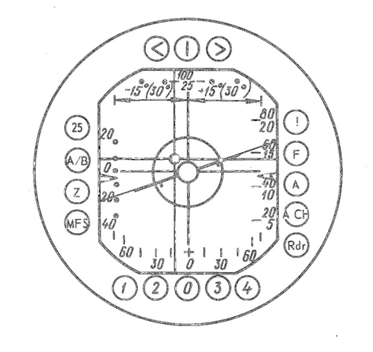
The indicator (Fig. 112) is installed above the instrument board in the aircraft cockpit. Marked on the protective glass panel in the centre of the indicator screen is a cross-hair with a ring the radius of which corresponds to the limit angle (45°) of the antenna beam mark deflection during missile launching.

FIG. 112. RP-25 RADAR INDICATOR

RP-25.png

On the right-hand side of the indicator screen, there is a range scale with 20, 40, 60, 80, and 100 division marks for the "100 km" scale and 5,10 ,15, 20, 25 for the "25 km" scale (in the LOW ALTITUDE mode).

Pitch angle indications are given by two triangular indexes arranged both on the right and left sides of the indicator screen. The pitch indicator scale is only on the left side of the screen and has divisions from -20 to +40°.
The bank indicator having a form of a miniature airplane is located in the centre of the screen. A bank indicator scale is omitted. The amount of bank is determined by the pilot approximately.

The position of a target in azimuth with respect to the centre of the scanning zone is determined by reference to the upper dial having divisions: at an interval of 5° within the limits of +.15° Рог the airborne radar operating in the automatic control mode; at an interval of 10° within the limits of ,+30°, with the airborne radar operating in the manual control mode. The position of the scanning zone centre relative to the aircraft longitudinal axis is to be determined by reference to the lower azimuth scale having divisions which are spaced at an interval of 15° within the limits of +60°.

Aircraft control is effected by reference to the director mark ("bead") which receives director signals from the automatic flight control system. The amount of displacement of the director mark on the indicator screen is proportional to the difference between the assigned and present values of bank and g-load.

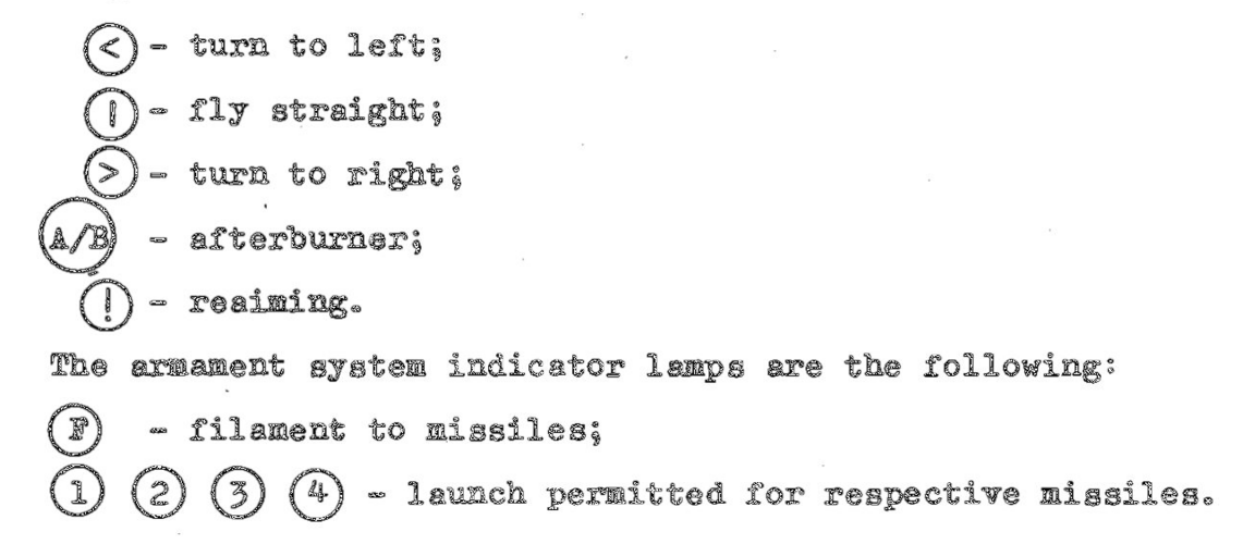
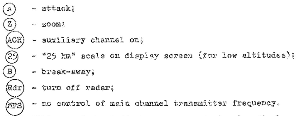
In front of the indicator screen there is an attitude - command marks unit. The circular display of the attitude - command marks unit is composed of seventeen lamps associated with the ground guidance, armament, and radar systems.

The indicator lamps of the ground guidance system are the following:
RP-25-1.png
The airborne radar incorporates the following indicator lamps:
RP-25-2.png

The brilliancy of the indicator screen and circular display
lamps is adjusted by rotating the polaroid glass panels of the
tube by the use of the special knob.
The indicator display screen photographing is effected by the
ПДУ-473 gun camera which is automatically cut in if the airborne
radar emission is ensured.

RP-25-3.png

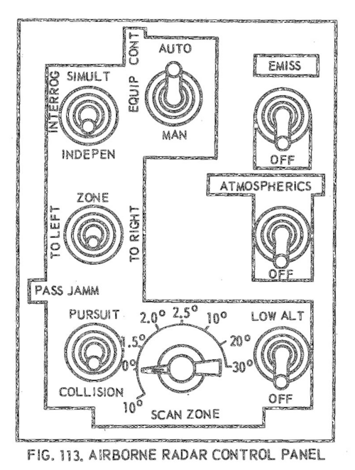
The radar control panel (Fig. 113) is arranged on the cockpit
instrument board and intended for effecting the main control
of the sight. The controls arranged on the radar control panel are
intended for the following purposes
  • the EQUIPMENT CONTROL (УПР. АППАР.) selector switch which is used for cutting in the airborne radar control means to operate either in manual or automatic control mode;
  • the EMISSION (ИЗЛУЧ.) selector switch which is used for cutting in the emitter;
  • the INTERROGATION (ЗАПРОС) selector switch which is used for turning on the CP3O-2 interrogator-responder to ensure target identification;
  • the ZONE (ЗОНА) selector switch which is used for shifting the scanning zone in azimuth either to the left or to the right in airborne radar manual control mode;
  • the SCANNING ZONE (ЗОНА 0БЗ.) selector switch which is used for manually shifting the scanning zone in elevation. The selector switch may be placed in the following positions: 10° (downward) and 0°; 1.5°; 2°; 2.5°; 10°; 20°; 30°) (upward);
  • the ATMOSPHERICS (МЕТЕОПОМЕХИ) selector switch which is intended to cut in the atmospherics protection circuit of the airborne radar;
  • the PASSIVE JAMMING (ПАСС. ПОМЕХА) selector switch which is used for cutting in the airborne radar passive jamming protection circuit;
  • the LOW ALTITUDE (МАЛ. ВЫСОТА) selector switch which is used for cutting in the LOW ALTITUDE mode.
RP-25-4.png

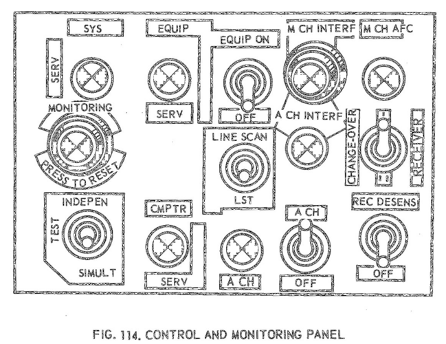
The airborne radar control and monitoring panel (Fig. 114) is arranged on the starboard side in the cockpit and is intended to ensure control and monitoring of the airborne radar. The controls arranged on the control and monitoring panel are intended for the following purposes:
  • the CH AFC (MAIN CHANNEL AUTOMATIC FREQUENCY CONTROL) (АПЧ OK) lamp comes on in the event of failure of the automatic frequency control system. If this lamp flashes up, this means that the target detection is impossible or the target detection range is sharply reduced;
  • the M CH INTRF (MAIN CHANNEL INTERFERENCE) (ПОМЕХА OK) button light is intended to indicate the occurrence of active jamming in the main channel. Target lock-on in angular coordinates completed, the pilot can cut in the auxiliary channel emitter by depressing the button light;
  • the EQUIPMENT ON (ВКЛ. АППАР.) selector switch which is used for turning on the airborne radar. As soon as this selector switch is closed, the airborne radar becomes ready for operation in 1 to 4 min;
  • the A CH INTRF (AUXILIARY CHANNEL INTERFERENCE) (ПОМЕХА ДК) lamp which comes to glow if active jamming occurs at the first frequency of the auxiliary channel;
  • the RECEIVER SELECTION (ПЕРЕКЛ. ПРИЕМН.) selector switch which is intended for cutting in either receiver I or receiver II of the main channel to operate in the scanning mode. Both the receivers are identical, but only one of them is engaged in scanning mode. The necessity in changing over the receivers may arise when the pilot is in doubt whether it is serviceable or not (no blip on the screen). The target detection is possible with the use of the second receiver if the first one is faulty, but the target lock-on is impossible in this case;
  • the LINE SCAN - LST (0B30P СТР. - МСЦ) selector switch which is used for cutting in the single-line scanning mode (LINE SCAN position), as well as for de-energizing the speed selection circuit (LST position), in performing an attack on a low-speed target and attacking at aspect angles above 2/4;
  • the RECEIVER DESENS (BATE. ПР-MA) selector switch is intended for manually switching on the main channel receiver desensitization circuit in the event of active jamming. With the desensitization circuit energized, the target detection range is H diminished one and a half or two times;
  • the A CH - OFF (ДК - ВЫКЛ.) is used for cutting off the I auxiliary channel receiver;
  • the A CH lamp is intended to indicate the deterioration of the auxiliary channel receiver thermal conditions. When the A CH lamp flashes up, it is necessary to turn off the auxiliary channel with the use of the A CH - OFF selector switch;
  • the pressure-type MONITORING - INDEPENDENT - SIMULTANEOUS (КОНТР. - ABTOH. - COBMEC.) selector switch is intended for switching on either the independent or simultaneous monitoring system. During the simultaneous monitoring, airborne radar, computer automatic flight control system, and armament system are checked for serviceability. The simultaneous testing equipment is to be used during ground testing of the systems only. It is permissible that the independent monitoring be switched on in flight too. In the independent monitoring only the airborne radar and the computer are checked for serviceability. The proper functioning of the airborne radar which is checked by the built-in monitoring system is indicated by the illumination of the EQUIPMENT SERVICEABLE (АППАР. ИСПР.) lamp. The serviceability of the computer is testified by the illumination of the COMPUTOR SERVICEABLE lamp. The serviceable condition of the armament system and automatic flight control system is evidenced by the flashing-up of the SYSTEM SERVICEABLE (СИСТ. ИСПР.) lamp. The switching-on of the built-in monitoring system is indicated by the MONITOR ON - DEPRESS TO RESET (КОНТРОЛЬ ИДЕТ - СБРОС НАЖАТЬ) button light. As soon as the button light is depressed, the monitoring is reset.
  • The guidance panel arranged on the port side of the cockpit is intended for manual guidance of the target lock-on zone (gate pulses), as well as for resetting target lock-on.
 
Last edited:
Very interesting RP-25 Smerch details above, thanks Overscan.

Just a comment to make on the RP-25MN Sapfir-25 radar. The weight listed on previous page at 337 kg must be an error, that would make it lighter than the S-23ML from which it was derived, considering that among other things has a bigger antenna that seems very unlikely. Perhaps it shoud be 537 kg? Has anyone ever seen a manual stating the weight of the Sapfir-25?
 
MISSILE R-40

1. PURPOSE AND BASIC PERFORMANCE

The R-40 airborne homing missile is designed for hitting various air targets (aircraft and winged missiles). The missile is essentially a winged flying vehicle having a canard configuration, that is the control surfaces are arranged ahead of the wings. For the purposes of enhancing the missile anti jamming capability with respect to jamming and natural noise the missile is manufactured in two versions:

  • with radar homing head (missile of the R-40R type) ;
  • with infra-red homing head ( the R-40T missile) .
The R-40 missile has the following basic performance :
  1. Flying altitude of targets to be intercepted :
    from 0 .5 to 27 km in rear-cone (rear hemisphere) attack ;
    from 2 .5 to 27 km in forward-cone (forward hemisphere ) attack.
  2. Maximum flying speed of targets to be hit during attack :
    up to 2400 km/h in rear hemisphere attack ;
    up to 5250 km/h in forward hemisphere attack .
  3. Maximum elevation of a target over the interceptor fighter ЛНщах is determined from the following equation
    ДНmax = 2000 + 0.2H1, where H. - interceptor-fighter flying altitude at the moment of missil launching , m.
  4. Permissible aiming error is determined from the following equation
    Aepermis 4 0 K ТЭ JS 1au"nch p e rm is . max where К- coefficient which takes account of missile launching conditions ;
    Bl.a u n c h - t a r g°e t ran g e a t th e moment o f m i s s i l e la u n ch ; B_ _.4 = - maximum p e rm i s s ib le la u n c h in g ran g e c a lc u -p e rm is . max i a t e d by th e computer o f th e РП-25 r a d a rs i g h t .
  5. Controlled flight maximum time accounts for 40 s .
  6. Maximum available g - load factor in the missile control channels accounts for 15.
  7. Maximum additional missile flying speed in variation with the launching altitude and speed ranges from 540 to 720 m /s.
  8. Minimum permissible missile-to-target approach speed depending on the fuze operation amounts up to 200 m /s.
  9. Operational radius of the proximity fuze , with the probability close to the unit : [Does it mean close to 1 ?]
    10 to 20 m against la rge-size targets ;
    6 to 7 m against pinpoint targets .
  10. missile starting mass is 470 kg.
  11. Warhead mass is 38 kg.
  12. Number of fragments accounts for 1800 pcs
  13. Mass of a single fragment equals 7g.
  14. Rocket engine operating time is from 4 to 6.7 s.
  15. Time of missile flight from the moment of launching till the moment of self-destruction ranges from 40 to 60 s.

2. MAJOR COMPONENTS AND SYSTEMS OF MISSILE

The P-40 missile comprises the following major accessories and systems:
  • missile body with wings and control surfaces;
  • powder rocket engine;
  • armament;
  • missile control equipment;
  • electrical equipment;
  • gas system;
  • cooling system;
  • pneumatic system (for the R-40R missiles only).
A tracer may be fitted to the tail portion of a missile to provide conveniency for observing a missile in flight during the firing practice.
The body is intended for housing the missile equipment.

Together with the wings and control surfaces it forms the missile aerodynamic system with required aerodynamic characteristics.
The powder rocket engine imparts a required speed to the missile for target interception. Propellant grain is initiated by means of a couple of squibs and an igniter. Powder gases rush out through two side nozzles to create jet thrust.

The armament of a missile consists of a fragmentation warhead, a combined radio-optical proximity fuze, contact electromagnetic sensors, and an actuator-and-safety mechanism. Some missiles R-40 are equipped with electronic fuzes instead of the combined radio-optical proximity fuzes. An additional warhead of 17 kg in mass and an actuator—and—safety mechanism are also provided.

The missile control equipment comprises an infra-red or radar homing head and automatic pilot which ensure missile guidance and stabilization in flight. A homing head is intended to generate electric control signals depending on the relative motion of a missile and a target into the missile control system.

The infra-red homing head incorporates a liquid nitrogen power pack which is intended for cooling the photo-detector of the head with liquid nitrogen.

The automatic pilot composed of control units and sensing devices is used for stabilizing a missile relative to the centre of masses and converting the electric control signals furnished by the homing head into the required angular deflection of the control surfaces and ailerons in accordance with the common guidance law.

The missile electrical equipment provides for the electric power supply and interaction of the missile accessories. The electrical equipment comprises a power pack, automatic control unit, conversion unit, and electric wire bundle network with plug connectors.

The gas equipment (gas system) is intended to provide hot gas to the turbogenerator of the power pack and the servo units of the autopilot. The gas equipment comprises a solid-propellant not gas generator, filter, and pipe-line system with fittings. The cooling equipment (cooling system) is used for maintaining the inner temperature inside the missile compartments within the prescribed limits to ensure proper functioning of the missile equipment. The missile cooling equipment incorporates a temperature pick-up, an airborne freon pneumatic connector, and a pipeline system with fittings.

The pneumatic equipment ensures operation of the radar homing head drive. The pneumatic equipment (pneumatic system) comprises an air package, a freon pneumatic connector, test connections, connections used for charging the air bottle which is integrated in the air package, and a pipe line system with fittings.

MISSILE LAUNCHING SYSTEM

The missile launching system provides for:
  • secure locking of missiles on launchers at any change in aircraft attitude;
  • reliable electric power and compressed air supply and cooling of missile sections with freon;
  • preparation of missiles for launching;
  • launching missiles in series by two or by one;
  • emergency jettisoning of missiles.

The missile launching system comprises the launching electrical automatic equipment, four launchers APU-4О, controls and indication system.

The electrical automatic equipment is essentially a package of separate units arranged in compartment No. 5 of the aircraft fuselage.

The launchers house a pneumatic system containing an amount of compressed air sufficient for 7-min continuous operation (for
the R-40R missiles), missile emergency jettison pneumatic system, cooling system with freon content sufficient for 10-min operation,
as well as locking, connect-release, warning, and interlocking mechanisms. Controls and indication system are located on the starboard and port sides of the cockpit, on the upper left-hand panel of the instrument board, and the instrument board annunciator.

Arranged on the cockpit port side is the MR SIMULATION - MSL, LG (ИМИТАЦИЯ MP - CC, ШАССИ) selector switch which is intended for switching off the interlock with respect to the position of the extended landing gear when checking the electrical automatic equipment on the ground.

The following circuit breakers are arranged on the cockpit starboard side:

  • the MSL INBD (CC ВНУТРЕН.) and MSL OUTBD (CC ВНЕШН.) circuit breakers which are used for energizing the electric circuits of the inboard and outboard missiles;
  • the EMERG INBD MSL JETTIS (АВАРИЙНЫЙ СБРОС CC ВНУТРЕН.) and EMERG OUTBD MSL JETTIS (АВАРИЙНЫЙ СБРОС CC ВНЕШН.) circuit breakers which are intended for switching on the inboard and outboard missile emergency jettison systems.

The upper left-hand panel of the instrument board accommodates
the following:

  • the MSL LNCH (ПУСК CC) circuit breaker which is used for energizing the missile launch circuits;
  • the <p^ - + RDR - <P0 (<Pjj - С РЛС - <PQ ) three-position selector switch which is used for changing over the electric circuitry to the automatic or semiautomatic (manual) mode of operation;
  • the FH - RH (ПП - ЗП) selector switch which is used for final preparation of missiles for launching during operation in the semiautomatic mode depending on the hemisphere of attack;
  • the SMALL - LARGE (МАЛАЯ - БОЛЬШАЯ) selector switch which is used for selecting the optimum amount of the proximity fuze action delay depending on the target size;
  • the TERRAIN - AIR (ЗЕМЛЯ - ВОЗДУХ) switch which is used in the TERRAIN position for de-energizing the proximity fuze when launching the missiles against ground targets;
  • the SERIES - SINGLE (СЕРИЯ - ОДИН) selector switch which is used for selecting the firing version;
  • the EMERG MSL JETTIS (АВАР. СБРОС CC) switch which is used for the missile emergency jettisoning.

The annunciator on the instrument board comprises the LH OUTBD MSL, (CC ВНЕШН. ЛЕВ.), RH OUTBD MSL (CC ВНЕШН. ПРАВ.), LH
INBD MSL (CC ВНУТР. ЛЕВ.) RH INBD MSL (CC ВНУТР. ПРАВ.) lamps intended for indicating the presence of the missiles on the respective launchers.

The lamps located on the radar sight indicator edging indicate the actual passage of the FILAMENT (НАКАЛ) signal at least to one of the missiles (lamp F ) and readiness of the missiles for launching (lamps (?), (?), (?) and (*)).
The firing button by means of which the airborne missiles are launched is arranged on the aircraft control stick.

COLLIMATING SIGHT K-10T

The K-1OT collimating sight is a simplest optical sight and is intended for aiming the missiles on visible targets in modes "Ф " and о о

Basic data:
- the angular amount of the large circle radius equals 120 mils (6°53');
- the angular' amount of the small circle radius equals 80 mils (4°36');
- the large division of the reticle equals 20 mils (l°09');
- the small division of the reticle equals 10 mils (0°J4.5');
- the angular size of the large line is 11.4 mils (O°39-5');
- the angular size of the small line is 5-7 mils (O°19.7')«
The collimating sight incorporates:
an optical system with a back-folding light filter;
a lamp with a brilliance adjustment potentiometer;
a mechanical duplicator.
 
Last edited:

Similar threads

Back
Top Bottom