American Aerospace Archive - The B-52 Competition of 1946…and Dark Horses from Douglas, 1947-1950

Yes, you were absolutely right, robunos. I hesitated to update the issue till I had solid documentary confirmation from the Douglas report on the Model 1211R-45 through 1211X-55 studies, (a full summary of which can be found on pp. 17-21 of "Mother Ships, Parasites and More..."). I'm still not 100% certain of which exact engines were used for the early Model 1211 studies; the nacelle contours changed as the series evolved, which may imply changes in power plants. Hopefully concrete info will eventually emerge.
 
Well, I have 'Motherships' downloaded as well, looking forward to reading it in due course...


cheers,
Robin.
 
When I saw Martin model 216-1 flying wing drawing, I had following impression.
(1)Each wing four engine propeller thrust line direction are different. Outer two engine propeller thrust line are almost horizontal, but inner two engine propeller thrust line directed upward.
(2)Engin cooling is by skin cooler? I see many steam cooling channel at wing cross section upper surface.
(3)Engine side round device is turbo supercharger?
(4)Engine intake air outlet nozzle is located wing under surface.
(5)Engine air intake size is very large. Engine is liquid cooling type, but located in air flow. Why?
 
blackkite said:
When I saw Martin model 216-1 flying wing drawing, I had following impression.
(1)Each wing four engine propeller thrust line direction are different. Outer two engine propeller thrust line are almost horizontal, but inner two engine propeller thrust line directed upward.
(2)Engin cooling is by skin cooler? I see many steam cooling channel at wing cross section upper surface.
(3)Engine side round device is turbo supercharger?
(4)Engine intake air outlet nozzle is located wing under surface.
(5)Engine air intake size is very large. Engine is liquid cooling type, but located in air flow. Why?

On (1), could this have been an attempt to deal with CG bombload issues? It would seem that altering the power for the inner, upward-inclined engines could add extra pitch control.
 
starviking said:
blackkite said:
When I saw Martin model 216-1 flying wing drawing, I had following impression.
(1)Each wing four engine propeller thrust line direction are different. Outer two engine propeller thrust line are almost horizontal, but inner two engine propeller thrust line directed upward.
(2)Engin cooling is by skin cooler? I see many steam cooling channel at wing cross section upper surface.
(3)Engine side round device is turbo supercharger?
(4)Engine intake air outlet nozzle is located wing under surface.
(5)Engine air intake size is very large. Engine is liquid cooling type, but located in air flow. Why?

On (1), could this have been an attempt to deal with CG bombload issues? It would seem that altering the power for the inner, upward-inclined engines could add extra pitch control.
HmHmHm.......Thanks a lot. :D I confirm that engine is liquid cooling turbocharged R-7755 by Jared-san's book.
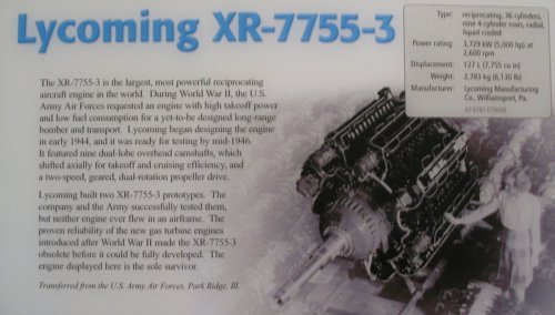
https://en.wikipedia.org/wiki/Lycoming_XR-7755

XR-7755 restoration.
http://www.people.virginia.edu/~rjr/engines/x7restored/
https://www.youtube.com/watch?v=lry0f21aPZI
Slide.
http://www.people.virginia.edu/~rjr/engines/Engineweb_files/v3_document.htm
 

Attachments

  • R-7755.jpg
    R-7755.jpg
    166.4 KB · Views: 72
Back
Top Bottom