A Tentative Fleet Plan
I really should change my personal text
- Joined
- 9 April 2018
- Messages
- 1,386
- Reaction score
- 3,476
I knew about the J58 and J93 proposals, but the Curtiss-Wright TJ60?

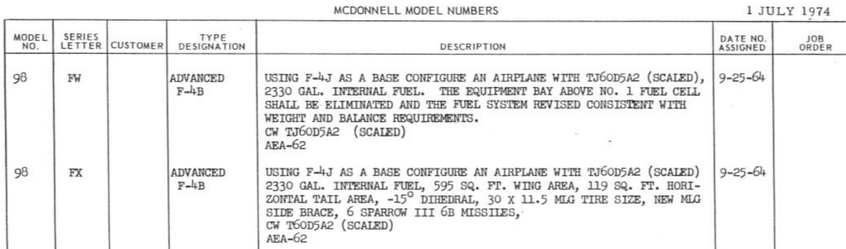


I know what a TJ60 is, I was under the impression that it was more powerful still than the J93 and J58, which would probably already provide a significant jump in performance over the original J79.
Spot the (scaled) after the engine? The TJ60D5A2 designation? That means it was a study using a scaled-down TJ60 to fit a Phantom. It was a Mach 3 engine design, so presumably this was intended to improve high speed performance.I know what a TJ60 is, I was under the impression that it was more powerful still than the J93 and J58, which would probably already provide a significant jump in performance over the original J79.
That would be one heck of a fun ride! Not entirely sure how they'd enlarge the engine bays from ~40" to 50" diameter, though...From a huge list of F-4 models in http://www.secretprojects.co.uk/ebooks/McDonnell Model Numbers List.pdf a few interesting ones.
[...]
98CN F-4H/ADC Phantom IIG Advanced Interceptor with AN/ASG-18 - wing and tail area inceased 20%, longer fuselage, two primary GAR-9, one alternate GAR-9, J93-MJ 252F engines. b) a 4 GAR-9 variant. (1960)
98CP Phantom IIF, as above with J58 engines (1960)
[...]
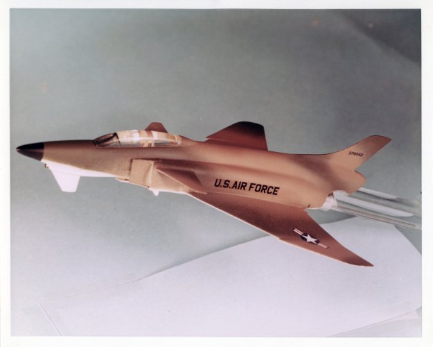
Yeah its more Phantomesque than Phantom.Thought that comes to mind about the high wing VG design: that's completely scrapping the existing wing box and most of the lower fuselage. Not sure how much tooling you'd be able to reuse.
Would this source have happened to mention what the job orders were? Just tracking or did they represent projects that were actually built and tested? Because the parts mentioning the GE-1 engine with the various bypass ratios have job orders, and quite a few more of the F-4 projects don't. Would be incredibly interesting to see the engine core design that evolved into the modern F110 used in a Phantom.From a huge list of F-4 models in http://www.secretprojects.co.uk/ebooks/McDonnell Model Numbers List.pdf a few interesting ones.
An interesting comment on this blogpost, quote: "I was Rey Smith’s test pilot on this project 50 years ago at China Lake. The fuel milage [sic] tests for the conformal configurations were fine but the super sonic bomb drops failed because the bombs tumbled and scattered going thru the shock waves making for widely dispersed unpredictable impacts". Commenter also leaves their email, left out for obvious reasons. Does explain why it wasn't adopted, if it supposedly gave such benefits to the Phantom. Doesn't help if the bombs can't drop accurately.In relation to the the Boeing Conformal Weapons Carriage / F-4 Phantom II configuration, I stumbled across the following interesting website:
http://phantomphacts.blogspot.com/2017/11/conformal-weapons-carriage-and-f-4.html?m=1
Notable for me is the great profiling artwork (including the 'Bluff Bomb' concept)!!
Regards
Pioneer
I imagine that's the near-mythical Navy J58 before it was turned into a Mach 3 frankenengine for the A-12... still big, though, it was generally substituted for the J79.That would be one heck of a fun ride! Not entirely sure how they'd enlarge the engine bays from ~40" to 50" diameter, though...
That just means you can't drop while supersonic. So stay under Mach 1 until bomb release, then punch it!An interesting comment on this blogpost, quote: "I was Rey Smith’s test pilot on this project 50 years ago at China Lake. The fuel milage [sic] tests for the conformal configurations were fine but the super sonic bomb drops failed because the bombs tumbled and scattered going thru the shock waves making for widely dispersed unpredictable impacts". Commenter also leaves their email, left out for obvious reasons. Does explain why it wasn't adopted, if it supposedly gave such benefits to the Phantom. Doesn't help if the bombs can't drop accurately.
I could easily envisage small short burst solid rockets used for positive supersonic/hypersonic stores separation.That just means you can't drop while supersonic. So stay under Mach 1 until bomb release, then punch it!
Youtube video on the Israeli adaption F4 Super Phantom that was quashed.
View: https://www.youtube.com/watch?v=qqFumSrkefg&t=304s

from
McDonnell F-4 Phantom: Spirit in the Skies
by Jon Lake, David Donald

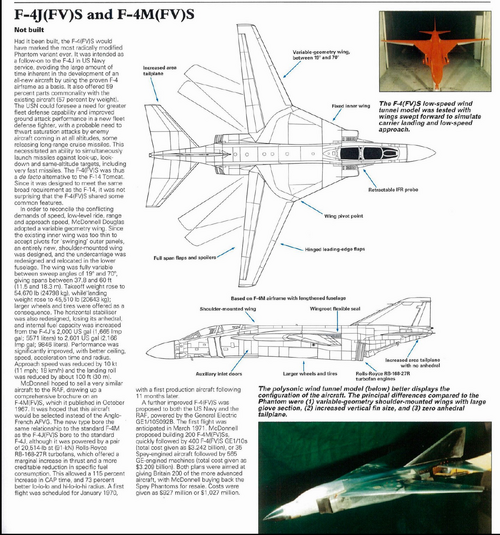
Wow,From the same source, the whole text.
is nothing to scoff at!a 115% increase in CAP time, and 73% better lo-lo-lo and hi-lo-lo-hi radius
With as much of the plane as was getting redesigned, I'd hesitate to call it a Phantom anymore...Would a swing-wing Phantom qualify as a 3.5 generation fighter I wonder?
With as much of the plane as was getting redesigned, I'd hesitate to call it a Phantom anymore...
The whole wing box and center fuselage is getting replaced in that design!
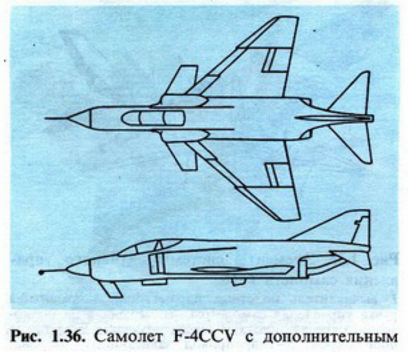
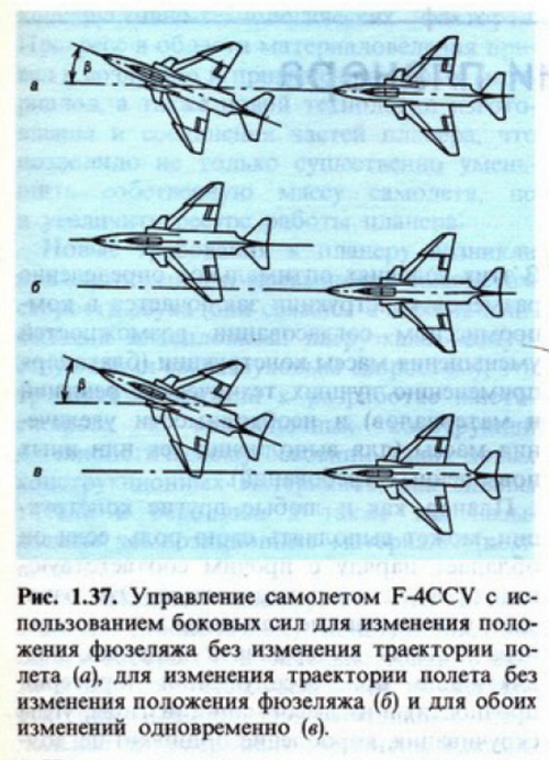
?Why the straight leading edge on the canards?From this report.


Greetings fightingirish, I've already worked on it, albeit in a small format. I'm going to review it and check the image quality. I also have a Grumman "Duck" project that's quite far along; I'll share it soon. MotocarHello folks, here is an X-ray illustration of the Phantom II+ concept.
I bet, @Motocar can do a better job cleaning it up...
Source: Air International, December 1985
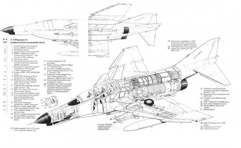
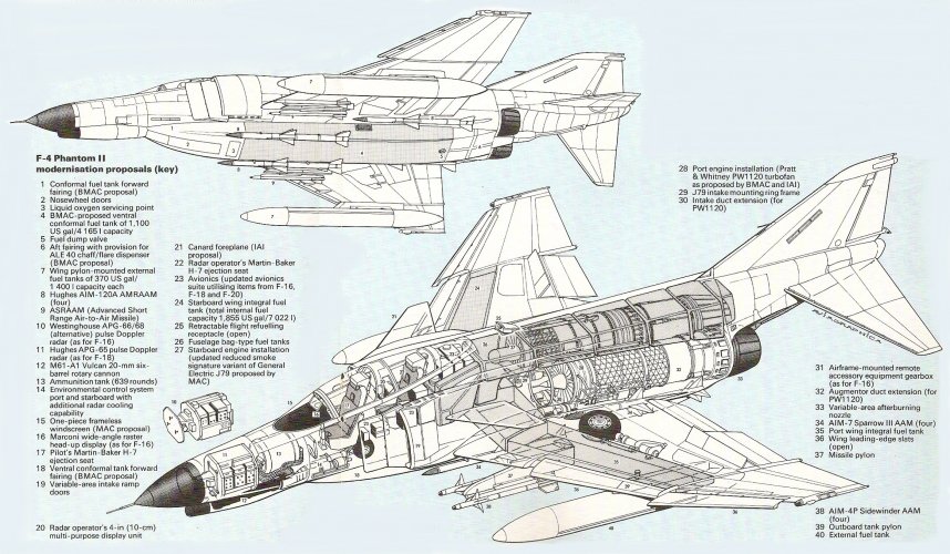
Hello folks, here is an X-ray illustration of the Phantom II+ concept.
I bet, @Motocar can do a better job cleaning it up...
Source: Air International, December 1985
Hello Motocar, just send you a PM.I was able to review the image, which is in small format and low quality, a real shame although I will still try to improve it but there is not much I can do.
Hello folks, here’s the 40-year-old article, in case anyone is asking for it. Happy new year!Hello folks, here is an X-ray illustration of the Phantom II+ concept.
[...]
Source: Air International, December 1985
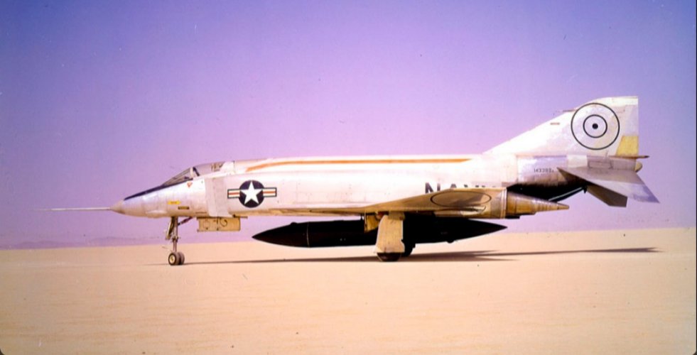
On second viewing of this photo, is it just me, or does that under-fuselage drop tank appear to be extra large?Also from N747GE, this F4H with nozzle plug.

IIRC, that tank carried the coolant for the nozzle.On second viewing of this photo, is it just me, or does that under-fuselage drop tank appear to be extra large?
Regards
Pioneer
Thanks Sundog, that makes a lot of sense.IIRC, that tank carried the coolant for the nozzle.
IIRC the F-4 was area ruled, but it's very subtle compared to the T-38.Out of curiosity, was there ever a McDonnell/McDonnell Douglas effort to aerodynamically clean up the F-4 Phantom II? After all, aerodynamically, it was a pig and for good reason referred to as the Flying Brick....
I can't help but think, had the F-4 Phantom II been aerodynamically refined, even the incorporation of area ruling, it's already two powerful J79's would have been able to be far more efficient and the Phantom II's overall flight performance as a fighter vastly improved....
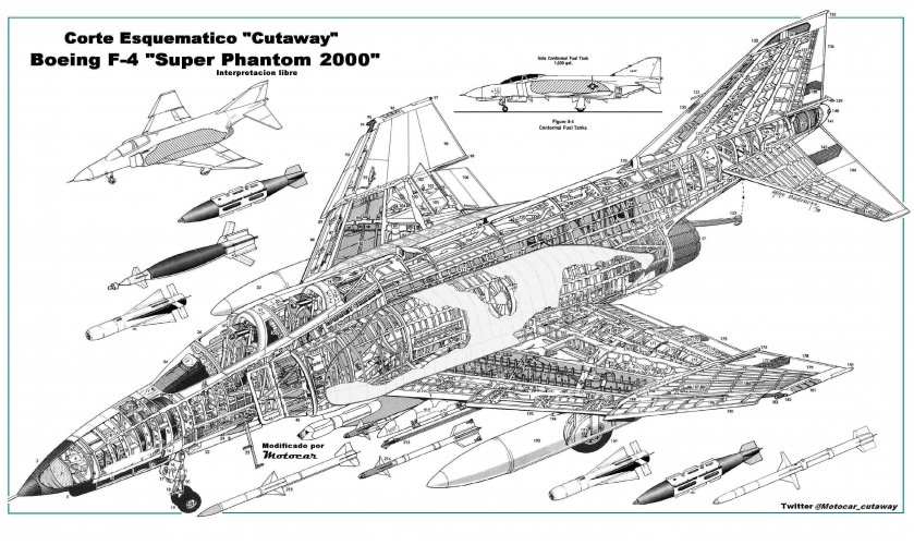
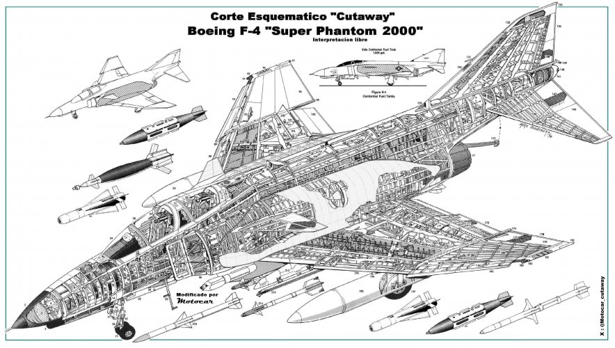
All -Now I share with you the work I had already done on Boeing's Super-Phantom, a proposal presented at LeBourguet in 1987, an interpretation of what I remember from a photograph that appeared in the old and now defunct magazine Interavia of July 87 (Issue that unfortunately I lost from the archive) with the new data I will recreate the canards and other details as well as I will retouch the cuts that you kindly shared here. thank you
Cutaway Boeing Super Phantom