From MCA to AMCA

Low IQ Techie

Low IQ, mid-aged, IT Engineer, Military enthusiast
Joined
4 December 2022
Messages
295
Reaction score
634
1776276729023.png


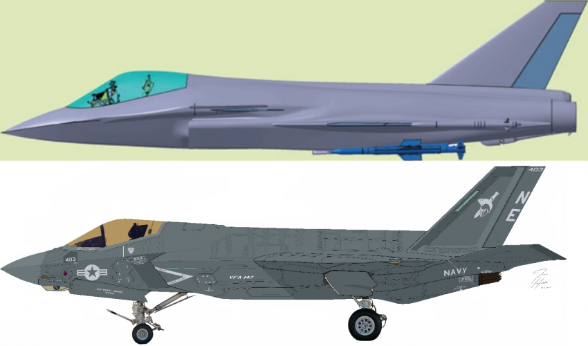
After adjusting pixels of available diagrams of TEDBF & AMCA to their dimensions & comparing, we found that their fuselage height is almost same; span & cross section area values are nearby, AMCA's belly spans more for IWB.

The overlay of AMCA's IWB outline shows that TEDBF can be tweaked towards 5gen (which i made last year but couldn’t show yet) or a cleansheet delta-canard jet.

But as AMCA is not made yet, let's see comparison with existing similar tandem bi-plane medium category naval jet design - F-35-C, matching the pixels with dimensions. This can help in understanding transitioning from STOBAR jet design to CATOBAR & explore a STOBAR stealth design.
NOTE - This TEDBF 3D CAD is slightly different from official greyscale images not good resolution.
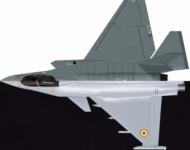
1778225987778.png

1778226001407.png

1778226014842.png

1778226028439.png


> From diagrams we can notice that -
- Like "Fat Amy", TEDBF looks chubby & voluminous too, but with smaller engines.​
- height of both fuselages are near equal,​
- From nose to exhaust, TEDBF seems to be longer,​
- F-35's fuselage width & wingspan is more due to IWB,​
- TEDBF nose is more tapered & drooped,​
- F-35's canopy is already big. TEDBF's canopy is way too big.​
- Rear half of F-35 packs cool stuff like cooling system, antennas, decoys, APU, counter-measures, etc. A 4gen jet may not have some of these things or not internally.​

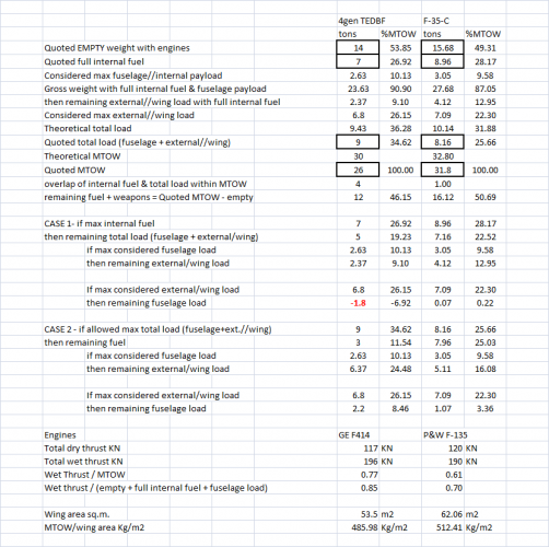
> Looking at numerical data -
- Total thrusts values look nearby,​
- but empty, gross, max weights, IWB load, fuel of TEDBF less than F-35's, perhaps bcoz CATOBAR has the catapult assist not on STOBAR,​
- hence the ATWR (A/c Thrust to Weight Ratio) of TEDBF is also more.​
- Wing area of F-35-C is more, but its weights increase in bigger ratio, so wing loading is more.​

More observations can be made.

> Take-off, gross weight, MTOW -
- Gross weight could be standard CAP config with certain fuel amount & minimum weapons. For my calculations i consider it as empty weight + full internal fuel + max fuselage load, analogous to a stealth jet.​
- In peace time light AA, AG, mixed loads are taken, just enough for CAP, to deter aggressors. MTOW is a war time capability which pushes A/c structural limits.​
- Common pattern in all fighter jets is observed that MTOW is roughly around or +/- of 2x empty weight.​
- MiG-29-K empty weight is 12 tons, quoted MTOW is 24.5 tons. With 2x RD-33MK engine's 88.3 KN thrust, wet T/MTOW = 0.74​
- Su-33 empty weight 18.4 tons, quoted MTOW 33 tons, < 2x empty weight. With 2x Al-31F3 engine's 125.5 KN thrust, wet T/MTOW = 0.78​
- F-35-C empty weight 15.68 tons, quoted MTOW 31.8 tons. With 1x F135 engine's 190 KN thrust, wet T/MTOW = 0.61​
- F-18-E empty weight 14.55 tons, quoted MTOW 29.93 tons, >2x empty weight. With 2x F414 engine's 117 KN thrust, wet T/MTOW = 0.67​
- TEDBF empty weight 14 tons, quoted MTOW 26 tons, <2x empty weight, due to STOBAR perhaps. With 2x 414 engine's 117 KN thrust, wet T/MTOW = 0.77​
- If aerial refuelling is available then T/o can be done with lesser fuel & more weapons.​
- Rear/longer T/o position is suitable for heavier load configs.​

> Landing & weight restrictions-
- On the deck side, arresting cables & deck itself are strong enough for stopping upto say 25-27 tons of aircrafts regularly. Structural limits are much higher with 50 tons C-130 landing tests in 1963 but risky & disruptive. Better cables are apparently designed for 6gen jets.​
- On the A/c side, that 27 tons becomes red line. Although max "Carrier Landing Weight" CLW of jets range around 63-80% of MTOW depending upon situations & strength of jet structure & cables.​
= Su-33 from searches appear to have CLW of 25 tons CLW, 75.75% of MTOW.​
= MiG-29K seems to have max CLW of 19.5 tons, 79.59% of MTOW.​
= F-35-C seems to have max CLW of 20.86 tons, 65.59% of MTOW.​
= F-18E is said to have CLW of 19-22 tons, 63.48-73.5% of MTOW.​
= If TEDBF CLW is also taken to be like F-18E then it is 16.5-19 tons.​
- All naval jets have "Carrier Bring Back Payload" CBBP (fuel + weapons), calculated as CLW - empty weight.​
= It has been observed to be in range of 13-30% of MTOW.​
= If heavier beyond CLW, the weapons, especially smart ones are expensive to be jetissoned, so some fuel is dumped.​

> Pattern noticed is that -
- While CATOBAR jets with catapult assist have ATWR range in 0.6X, or relatively more weight, less thrust.​
- STOBAR jets need more ATWR in range of 0.7X, or more thrust, less weight.​
- To tweak TEDBF into 5+G design this ATWR range & CLW range will have to be maintained.​
 
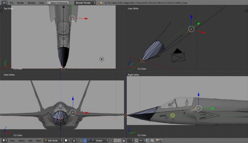
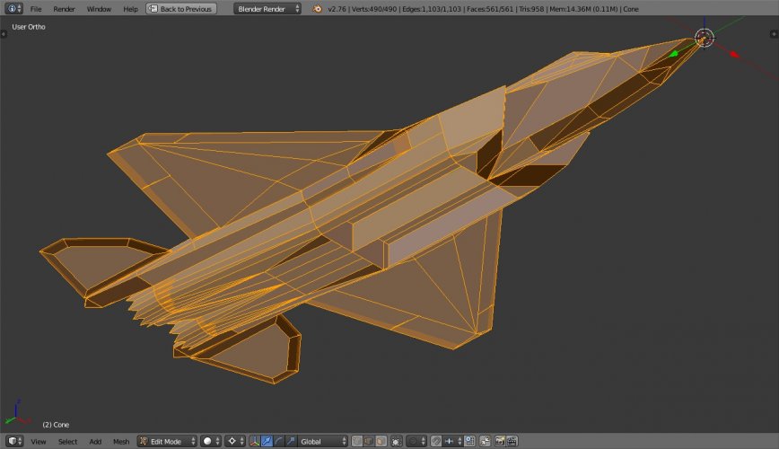
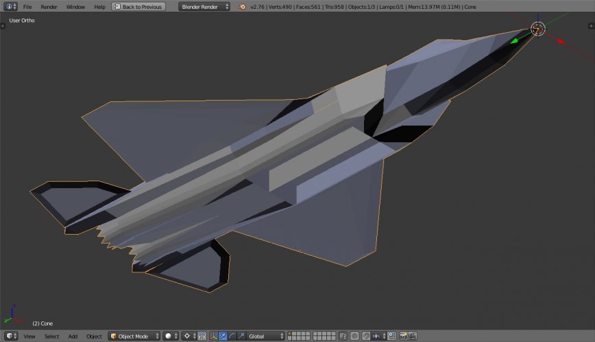
AMCA is getting assembled in the factory:oops:.....
i mean with Blendero_O....
i mean it won't have that juicer/mixer/blender, but its CAD is getting assembled with Blender S/w's factory settings. :D
 
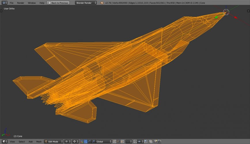
CAD work in progress.
Only surface outline so far based on low-res drawings.
At certain places like dorsal/upper curves, it's difficult to match exact contours from low res drawings, & 3D views.
Keeping low count of vertices, edges, polygons on old laptop.
I've removed some diagonal edges of low bending quadrilaterals where we don't need a crease, Blender displays them smooth enough.
Many small features are remaining like landing gear doors, sensors, etc.
Considering engine exhaust diameter = 90cm, the max dia. of F414.
 

Attachments

  • AMCA Blender, 29 July'26, edit  mode, wire-frame, all selected, front right low angle.jpg
    AMCA Blender, 29 July'26, edit mode, wire-frame, all selected, front right low angle.jpg
    407.1 KB · Views: 86
  • AMCA Blender, 29 July'26, edit mode, solid, all secleted, front right low angle.jpg
    AMCA Blender, 29 July'26, edit mode, solid, all secleted, front right low angle.jpg
    321 KB · Views: 74
  • AMCA Blender, 29 July'26, object mode, solid, front right low angle.jpg
    AMCA Blender, 29 July'26, object mode, solid, front right low angle.jpg
    200.6 KB · Views: 91
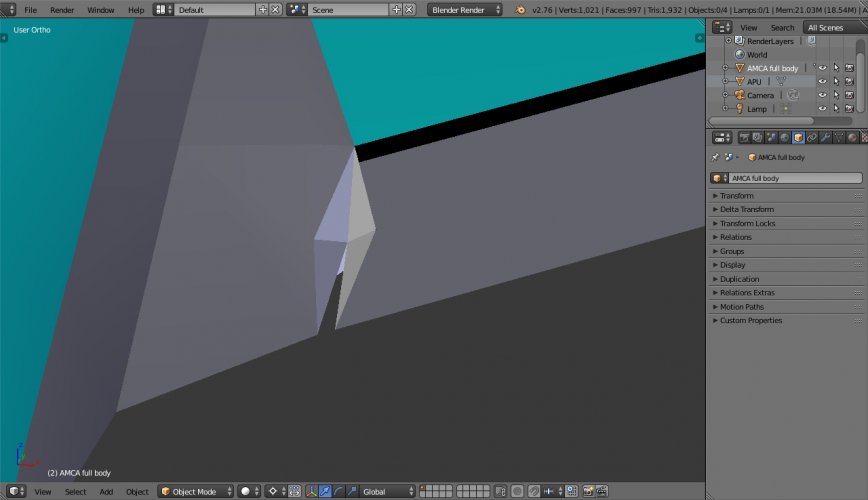
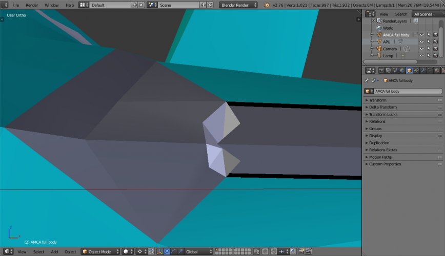
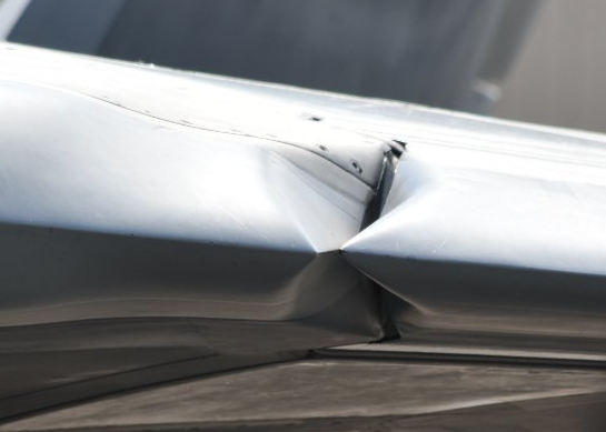
The gaps between control surfaces & body have to be angled, otherwise vertical side becomes side reflector.
The following is example of F-22's slat's gap with wing root -
[[ check attachment ]]

AMCA Static models focus on broad outline & have not shown the feature yet, but the real jet would apparently have it.
[[ depiction in CAD attachment ]]
 

Attachments

  • AMCA Blender, 6 Aug'26, gap between slats & wing root, object mode, solid view, front top angle.jpg
    AMCA Blender, 6 Aug'26, gap between slats & wing root, object mode, solid view, front top angle.jpg
    192.4 KB · Views: 63
  • AMCA Blender, 6 Aug'26, gap between slats & wing root, object mode, solid view, front angle.jpg
    AMCA Blender, 6 Aug'26, gap between slats & wing root, object mode, solid view, front angle.jpg
    225.2 KB · Views: 58
  • 1786031872531.png
    1786031872531.png
    160 KB · Views: 93
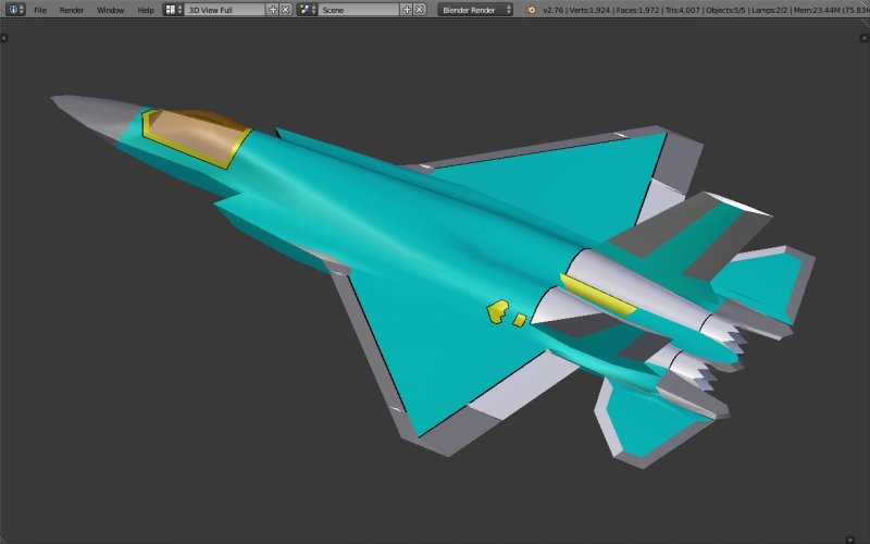
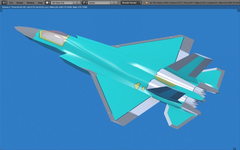
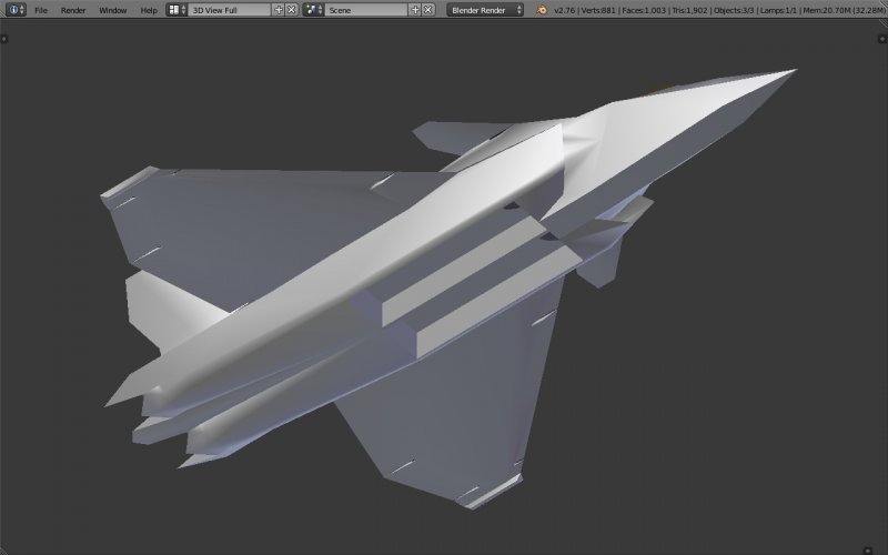
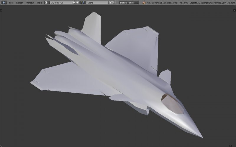
Basic CAD model outline of AMCA is ready.
Solid & rendered views in green primer, stealthy tinted canopy.
Cockpit is empty, needs time to model small area with right measurements.
Full surface features remaining, will model 1 by 1.
Started with F-22 model but AMCA got ahead so far.
Fortunately my old laptop didn't crash or hang bcoz Blender's old versions also work sufficiently well for discussion purpose. No GPU needed, just 100-150 MB RAM with Core-2 Duo CPU.
I'll be tweaking this basic CAD as per my comprehension, but i wanted 1st to make a model closest to used in official infographics, so that we can discuss what improvements can be made with minimum modifications, like FOC & MLU.
 

Attachments

  • AMCA Blender, 10 aug'26, object mode, solid view, left side, rear elevated angle,1280x800p.jpg
    AMCA Blender, 10 aug'26, object mode, solid view, left side, rear elevated angle,1280x800p.jpg
    202.5 KB · Views: 69
  • AMCA Blender, 10 aug'26, object mode, rendered view, left side, elevated angle, 1280x800p.jpg
    AMCA Blender, 10 aug'26, object mode, rendered view, left side, elevated angle, 1280x800p.jpg
    430 KB · Views: 74
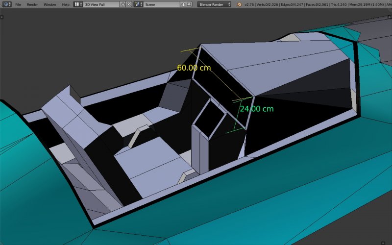
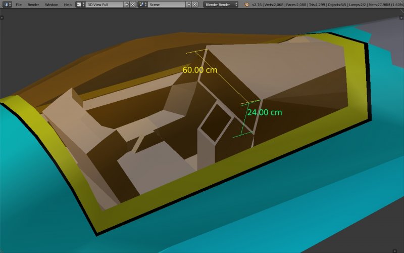
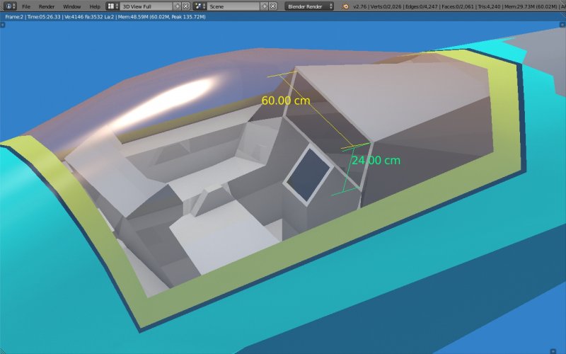
Initial outline of notional cockpit.
1 piece canopy w/o arc.
HMDS instead of HUD.
60 x 24 cms TV, i mean MFD.
From F-22 to F-35, we notice many hard switches, buttons, dials, knobs have been offloaded to MFD & HMDS.
 

Attachments

  • AMCA. blender, 12 aug'26, notional cockpit outline, Edit mode, Solid view, right side rear ele...jpg
    AMCA. blender, 12 aug'26, notional cockpit outline, Edit mode, Solid view, right side rear ele...jpg
    337.1 KB · Views: 29
  • AMCA. blender, 12 aug'26, notional cockpit outline, Object mode, Solid view, right side rear e...jpg
    AMCA. blender, 12 aug'26, notional cockpit outline, Object mode, Solid view, right side rear e...jpg
    285.5 KB · Views: 26
  • AMCA. blender, 12 aug'26, notional cockpit outline, Object mode, Rendered view, right side rea...jpg
    AMCA. blender, 12 aug'26, notional cockpit outline, Object mode, Rendered view, right side rea...jpg
    490.5 KB · Views: 34
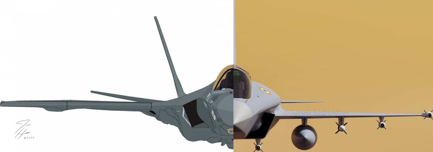
So far we compared diagrams of TEDBF with AMCA, F-18 SH, F-35-C, matching pixels with dimensions.
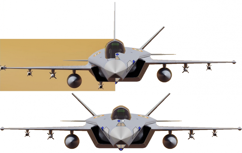
Here is an attempt to look at Notional 5gen TEDBF, as close as possible to the 4gen delta-canard TEDBF.
I made this edit last year itself & on day of posting the F-47 was announced.
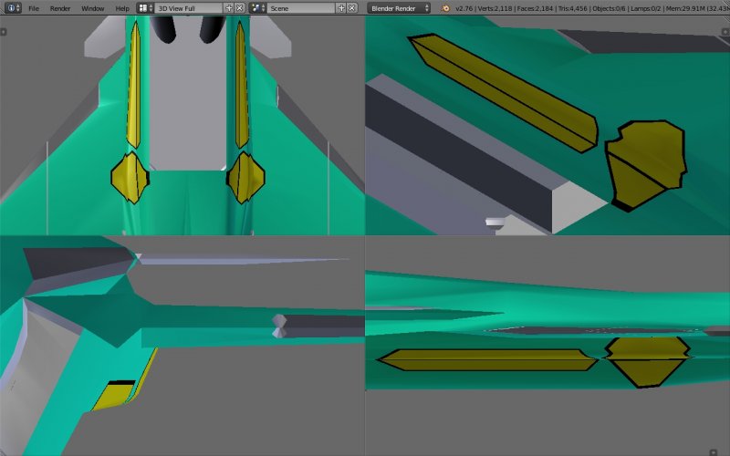
- pulled up the intakes,
- re-shaped the fuselage to make it less humpy bumpy like Humpty Dumpty, :D
- gave it shorter all-moving twin V-tail.
- add IRST on nose & EOTS on chin.
- add side shared multi-function RF-array & DAS on cheeks
- fuselage will be at least 2.2m wide like in AMCA, to carry AGMs & 6x AAMs.

I wonder if close-coupled canards need to be at higher level than wings like in Rafale or can be at same level.
 

Attachments

  • 5gen TEDBF Vs 4gen TEDBF half-half & full 5gen TEDBF, front view, cropped,PNG.png
    5gen TEDBF Vs 4gen TEDBF half-half & full 5gen TEDBF, front view, cropped,PNG.png
    352.9 KB · Views: 77
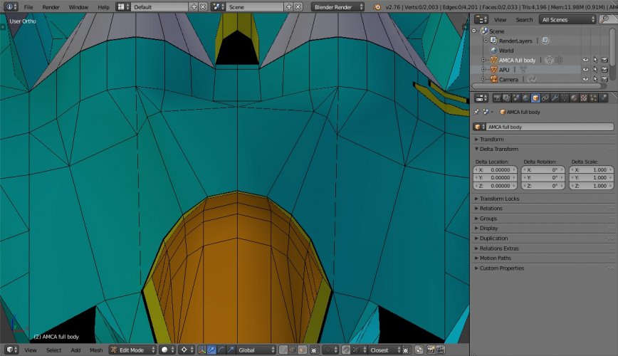
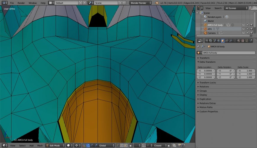
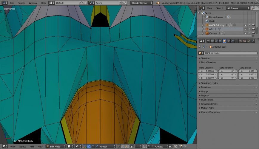
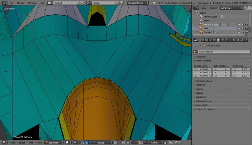
Different static models & CADs have shown minor differences in fuselage shaping & features.
I wonder which forward & mid fuselage blending contour style is best balance b/w aerodynamics, stealth, needed space.
This will affect components like S-duct, fuel tanks, sensors, etc.
I guess i'll have to make the S-Duct 1st & see if it gets out of any contour boundary.
Then decide the contour, then place the surface sensors & features.
 

Attachments

  • AMCA blender, 18 aug'26, fwd & mid spine blend modification-1, Edit mode, Solid view, front el...jpg
    AMCA blender, 18 aug'26, fwd & mid spine blend modification-1, Edit mode, Solid view, front el...jpg
    479.9 KB · Views: 16
  • AMCA blender, 18 aug'26, fwd & mid spine blend modification-2, Edit mode, Solid view, front el...jpg
    AMCA blender, 18 aug'26, fwd & mid spine blend modification-2, Edit mode, Solid view, front el...jpg
    432.7 KB · Views: 11
  • AMCA blender, 18 aug'26, fwd & mid spine blend modification-3, Edit mode, Solid view, front el...jpg
    AMCA blender, 18 aug'26, fwd & mid spine blend modification-3, Edit mode, Solid view, front el...jpg
    477.5 KB · Views: 10
  • AMCA blender, 18 aug'26, fwd & mid spine blend modification-4, Edit mode, Solid view, front el...jpg
    AMCA blender, 18 aug'26, fwd & mid spine blend modification-4, Edit mode, Solid view, front el...jpg
    440.7 KB · Views: 17
I guess i'll have to make the S-Duct 1st & see if it gets out of any contour boundary.
Then decide the contour, then place the surface sensors & features.
I'd recommend going with whichever surface has the best coke-bottle shaping. (Sorry, the proper name for that has completely escaped me today.)
 
I'd recommend going with whichever surface has the best coke-bottle shaping. (Sorry, the proper name for that has completely escaped me today.)

Coke-bottle, LOL!
I tried an initial duct from DSI to engine & its boundary peeked out of fuselage. So i reduced mid-duct diameter.

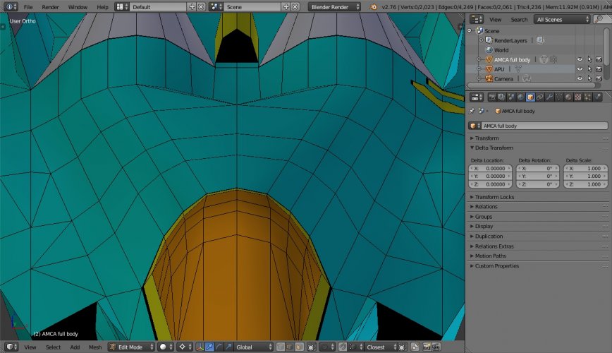
Another thing to notice in all stealth fighters is that the duct cuts through the forward wall & ceiling of IWB. This is clearly visible in pics of belly when these jets open their IWB doors at air shows.

For now i'm taking a default. end to end straight connection contour b/w cockpit & mid fuselage.
So 1st i'll curve in the S-duct from DSI towards center, then outwards along the straight contours backwards.
Once the S-duct is made, later i can decide the final contour
 

Attachments

  • AMCA blender, 18 aug'26, fwd & mid spine blend default, Edit mode, Solid view, front elevated ...jpg
    AMCA blender, 18 aug'26, fwd & mid spine blend default, Edit mode, Solid view, front elevated ...jpg
    437.9 KB · Views: 18
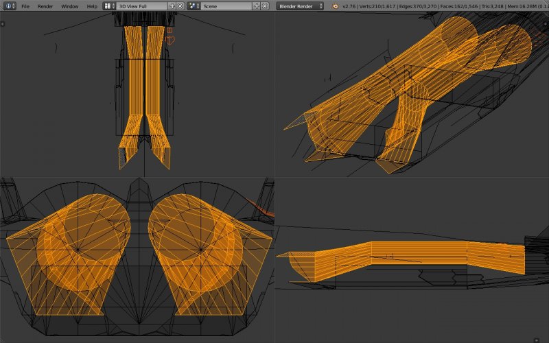
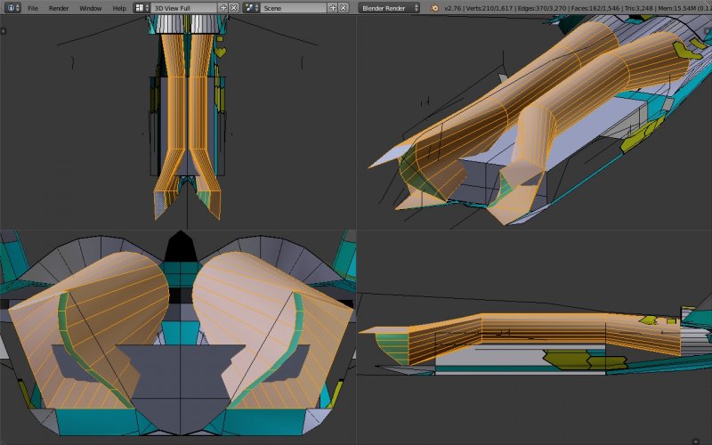
Theoretical straight segments diverging S-Duct.
Engine face not visible through corner of DSI intake for stealth.
Duct cuts through IWB's front upper part.
Theoretically, space for SWB also available but in a medium class jet perhaps that's needed for sufficient internal fuel & equipment. Later i'll check CAD body volume & compare with other jets.
 

Attachments

  • AMCA Blender, 24 aug'26, theoretical straight sections S-duct, quad view, Edit mode, wireframe...jpg
    AMCA Blender, 24 aug'26, theoretical straight sections S-duct, quad view, Edit mode, wireframe...jpg
    550.6 KB · Views: 10
  • AMCA Blender, 24 aug'26, theoretical straight sections S-duct, quad view, Edit mode, Solid vie...jpg
    AMCA Blender, 24 aug'26, theoretical straight sections S-duct, quad view, Edit mode, Solid vie...jpg
    488.4 KB · Views: 10
Theoretical straight segments diverging S-Duct.
Engine face not visible through corner of DSI intake for stealth.
Duct cuts through IWB's front upper part.
Theoretically, space for SWB also available but in a medium class jet perhaps that's needed for sufficient internal fuel & equipment. Later i'll check CAD body volume & compare with other jets.
That's not necessarily a problem.

Missiles etc do taper down to a point, so you can likely lose up to about a third of the front corner of the IWBs without actively losing weapons capacity.
 
That's not necessarily a problem.

Missiles etc do taper down to a point, so you can likely lose up to about a third of the front corner of the IWBs without actively losing weapons capacity.

Yeah it's not problem but expected, already mentioned in previous post.

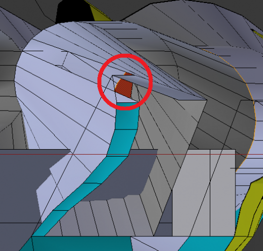
Real duct design needs CFD tools.
If i push the bend above IWB further back then the engine face will start becoming visible through DSI corner.
So i had to extend the DSI bump back little to cover this gap.
 

Attachments

  • 1787642032208.png
    1787642032208.png
    85.5 KB · Views: 101
Last edited by a moderator:
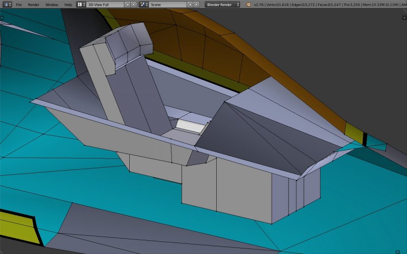
The cockpit section reminds me of baby stroller & bath tub :D
 

Attachments

  • AMCA Blender, 27 aug'26, cockpit, Edit mode, Solid view, front right elevated angle.jpg
    AMCA Blender, 27 aug'26, cockpit, Edit mode, Solid view, front right elevated angle.jpg
    365.5 KB · Views: 63
Last edited by a moderator:
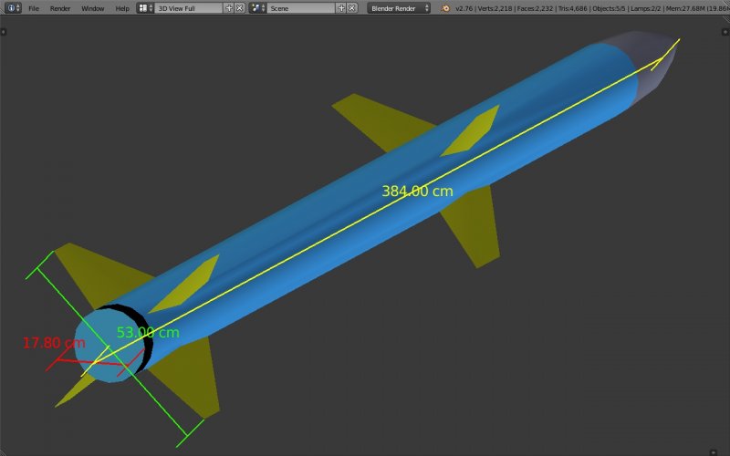
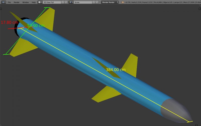
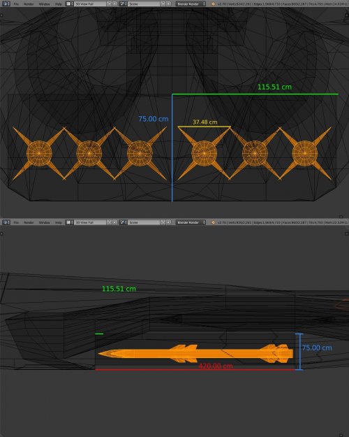
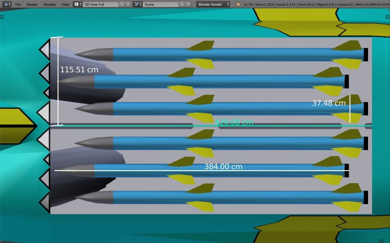
Considering notional Astr-2 short-fin AAM length = 3.84 m, diameter = 178 mm, fin-span = 530 cm.
IWB length = 4.2 m, depth = 0.75 m max, width = 2.3 m.
The IWB cannot be perfectly cuboid, but dynamic as per all the weapons needed & equipment around it.
 

Attachments

  • AMCA Blender, 31 aug'26, Astr-2 short-fin AAM, Object mode, Solid view, rear right elevated an...jpg
    AMCA Blender, 31 aug'26, Astr-2 short-fin AAM, Object mode, Solid view, rear right elevated an...jpg
    192.6 KB · Views: 6
  • AMCA Blender, 1 sep'26, Astr-2 short-fin AAM, Object mode, Solid view,front right elevated angle.jpg
    AMCA Blender, 1 sep'26, Astr-2 short-fin AAM, Object mode, Solid view,front right elevated angle.jpg
    190.6 KB · Views: 5
  • AMCA Blender, 1 sep'26, 6x staggered Astr-2 short-fin AAMs in IWB, Edit mode,Wireframe view, A...jpg
    AMCA Blender, 1 sep'26, 6x staggered Astr-2 short-fin AAMs in IWB, Edit mode,Wireframe view, A...jpg
    461.5 KB · Views: 8
  • AMCA Blender, 1 sep'26, 6x staggered Astr-2 short-fin AAMs in AMCA's IWB,Object  mode, Solid v...jpg
    AMCA Blender, 1 sep'26, 6x staggered Astr-2 short-fin AAMs in AMCA's IWB,Object mode, Solid v...jpg
    336.6 KB · Views: 21
CAD work in progress of 1st iteration of notional 5+G TEDBF, Delta-Canard, V-tail, IWB for AGMs. Alternate of Naval AMCA. :oops:
 

Attachments

  • 5gen TEDBF, 1st iteration, 7 Sep'26,  Object mode, Solid view, right front low angle.jpg
    5gen TEDBF, 1st iteration, 7 Sep'26, Object mode, Solid view, right front low angle.jpg
    152.3 KB · Views: 29
  • 5gen TEDBF, 1st iteration, 7 Sep'26, Object mode, Solid view, top right front angle.jpg
    5gen TEDBF, 1st iteration, 7 Sep'26, Object mode, Solid view, top right front angle.jpg
    140.2 KB · Views: 30
@overscan (PaulMM)

Just a question ... this thread looks IMO - since that type so far is anyway still more a project than anything real - more like a "member's artwork thread than truly relevant posting FACTS on that project and should be moved into the User Artwork and Models section!

This - especially the latest posts - have NOTHING to to with the TEDBF!
 
@overscan (PaulMM)

Just a question ... this thread looks IMO - since that type so far is anyway still more a project than anything real - more like a "member's artwork thread than truly relevant posting FACTS on that project and should be moved into the User Artwork and Models section!

This - especially the latest posts - have NOTHING to to with the TEDBF!

If you wanna maintain official news only, then like "MCA to AMCA" art work thread , you can separate a thread to something like TEDBF speculation thread.
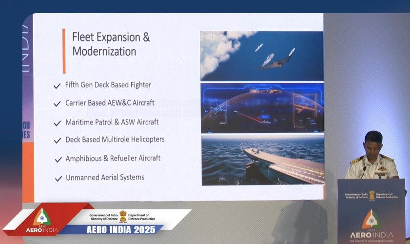
Just FYI, Indian Navy at Aero India 2025 indicated 5gen TEDBF (check attachment). So if 4gen TEDBF is made it'll get lot of backlash.
Hence this CAD (with minimum modifications in same footprint & GE F414 class engines) is like a speculation & expectation of Indian Navy & citizens.
 

Attachments

  • 5gen TEDBF indication at Aero-India'25, original.jpg
    5gen TEDBF indication at Aero-India'25, original.jpg
    197.1 KB · Views: 28
If you wanna maintain official news only, then like "MCA to AMCA" art work thread , you can separate a thread to something like TEDBF speculation thread.
Just FYI, Indian Navy at Aero India 2025 indicated 5gen TEDBF (check attachment). So if 4gen TEDBF is made it'll get lot of backlash.
Hence this CAD (with minimum modifications in same footprint & GE F414 class engines) is like a speculation & expectation of Indian Navy & citizens.

My point is simply, regardless as much as I apprechiate your skills and efforts, all the recent posts are speculative, non-official artwork and since we have a dedicated thread for User artwork, I suggest, all thsi non-official stuff and guesswork especially now on a 5th gen should not be posted in thsi section.
 
My point is simply, regardless as much as I apprechiate your skills and efforts, all the recent posts are speculative, non-official artwork and since we have a dedicated thread for User artwork, I suggest, all thsi non-official stuff and guesswork especially now on a 5th gen should not be posted in thsi section.

Yeah i got your point & i'm ok bcoz there's no official 5gen TEDBF program initiated yet. I can see many speculation threads on NGAD, etc for example. I can't wait for ADA for 5-10 years to initiate 5gen TEDBF, LOL! :D

But if you wanna keep all Indian jet speculations in same thread then please change name of this thread to something generic like "Indian jet speculations", etc.

BTW the AMCA CAD has been made on official drawings of DRDO, ADA. There was no need to separate it here.
 
Any artwork done by users belongs in User Artwork and Models, even if you used official drawings as the basis. This principal was established for the Project topics, so user artwork didn't get wrongly attributed as official data on said projects.
 
2D edits're not enough to imagine everything. 3d helps in rectification. I was going to just cut MLG bay door & color it separately. But rear tyre retraction, rest position affects fuselage shape. It shouldn't -
- touch the air duct
- overlap with IWB much
- peek out of fuselage much
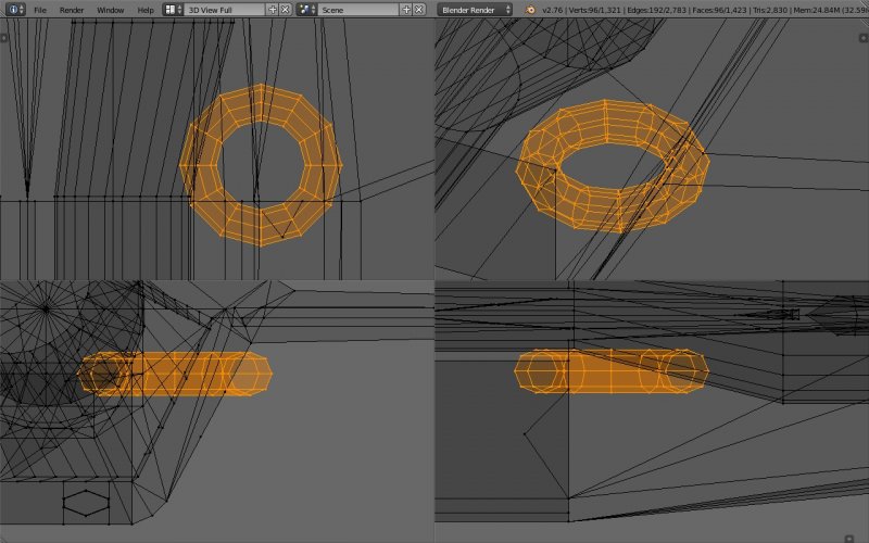
I'm considering a lateral folded retraction like in F-18 SH, F-22 & not unfolded forward/rear retraction, keeping it just behind IWB with small overlap in top corner. The peek-out of fuselage has to be covered aerodynamically like in most 5gen jets. This'll give space for SWB also.

As per search, rear tyre diameters of F-18 is 30"/76.2cm, F-35-C is 34"/86.4cm, F-22 is 37"/94cm.
For now i'm considering 5gen TEDBF's rear tyre diameter to be 90cm.
 

Attachments

  • 5gen TEDBF, 1st iteration, 13 Sep'26, Edit mode, Wireframe view, rear tyre selected, quad view.jpg
    5gen TEDBF, 1st iteration, 13 Sep'26, Edit mode, Wireframe view, rear tyre selected, quad view.jpg
    469.4 KB · Views: 16
  • 5gen TEDBF, 1st iteration, 13 Sep'26, Edit mode, Solid view, rear tyre selected, quad view.jpg
    5gen TEDBF, 1st iteration, 13 Sep'26, Edit mode, Solid view, rear tyre selected, quad view.jpg
    317.8 KB · Views: 12
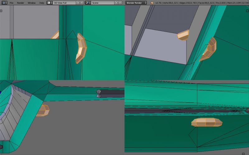
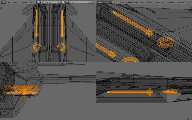
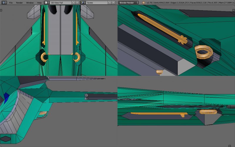
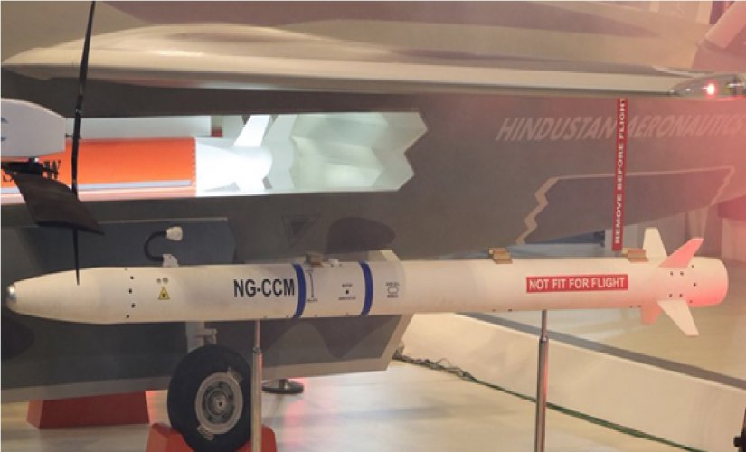
5+gen TEDBF can have SWB. Even if IWB is considered cuboid for AGMs, there is sufficient volume for CCM.
The lateral retraction of MLG would enable this easily, otherwise more modification of fuselage needed.
DRDO's NG-CCM is like AIM-132 ASRAAM which India also imports.
So here is the depiction of the CCM, SWB door.
 

Attachments

  • 5gen TEDBF, 1st iteration, 18 Sep'26,Edit mode, Wireframe view, MLG door & SWB door hidden, CC...jpg
    5gen TEDBF, 1st iteration, 18 Sep'26,Edit mode, Wireframe view, MLG door & SWB door hidden, CC...jpg
    537.5 KB · Views: 7
  • 5gen TEDBF, 1st iteration, 18 Sep'26, Edit mode, Solid view, MLG door & SWB door hidden, CCM &...jpg
    5gen TEDBF, 1st iteration, 18 Sep'26, Edit mode, Solid view, MLG door & SWB door hidden, CCM &...jpg
    463.6 KB · Views: 8
  • 5gen TEDBF, 1st iteration, 18 Sep'26, Object mode, Solid view, MLG door & SWB door, quad view.jpg
    5gen TEDBF, 1st iteration, 18 Sep'26, Object mode, Solid view, MLG door & SWB door, quad view.jpg
    279.4 KB · Views: 10
  • NG-CCM.jpg
    NG-CCM.jpg
    155.3 KB · Views: 9

Similar threads

Back
Top Bottom