Hello Everyone, firstime posting here.
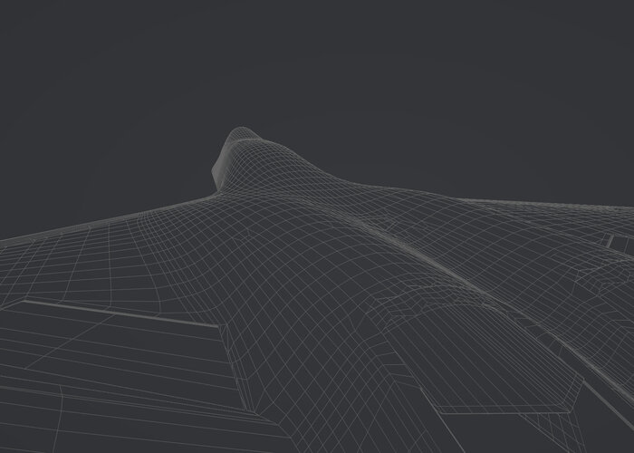
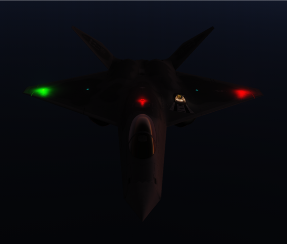
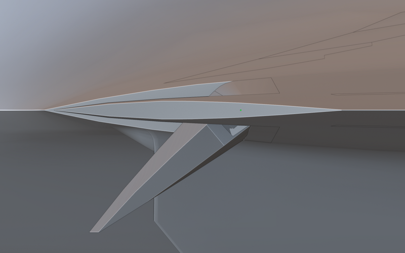
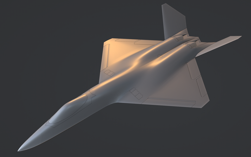
For the past couple years I have been working on a F-23A Model in Blender. I have been through a bunch of iterations and artistic license version of that particular aircraft including a two seat navalized version. However I have decided to create a more true to what could've been version and essentially re-did the model from scratch. I have had particular issues with all my iterations, when it comes to certain aspects of the model that are not well represented or explained in enough detail in any of the material I came across (I have the Paul Metz book and the Japanese picture book).
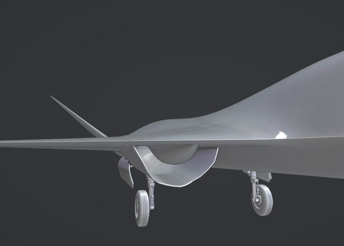
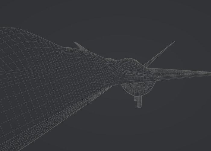
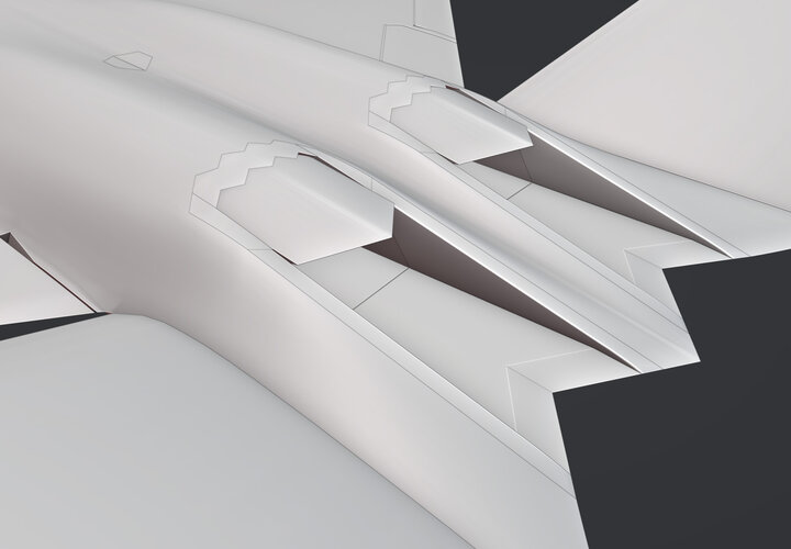
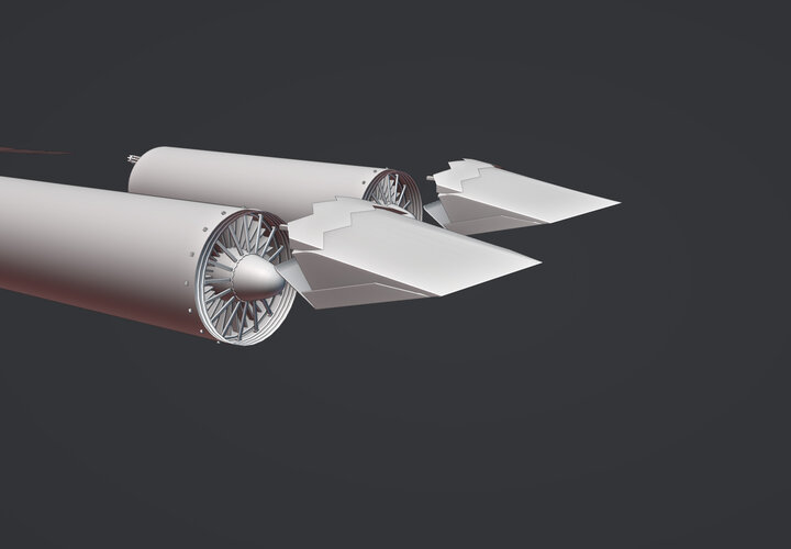
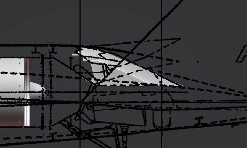
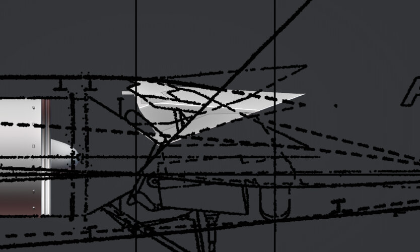
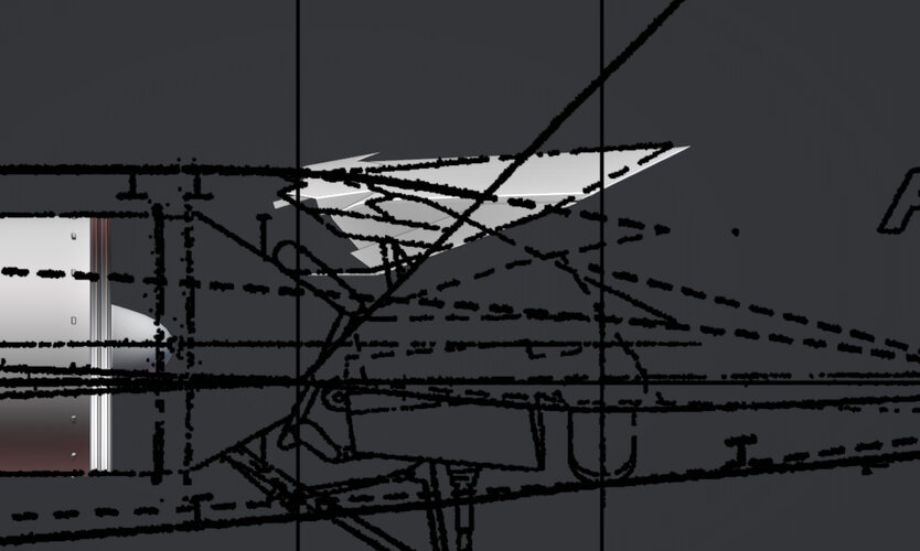
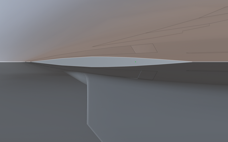
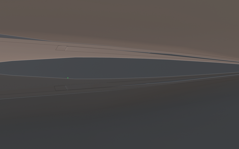
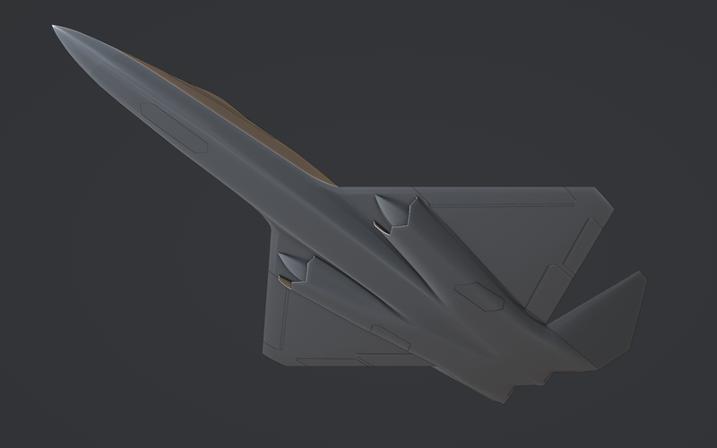
Those are the control surfaces.
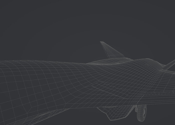
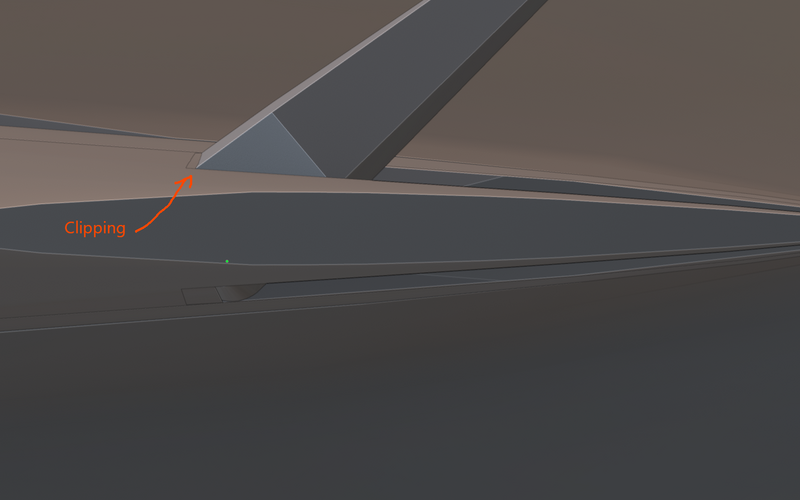
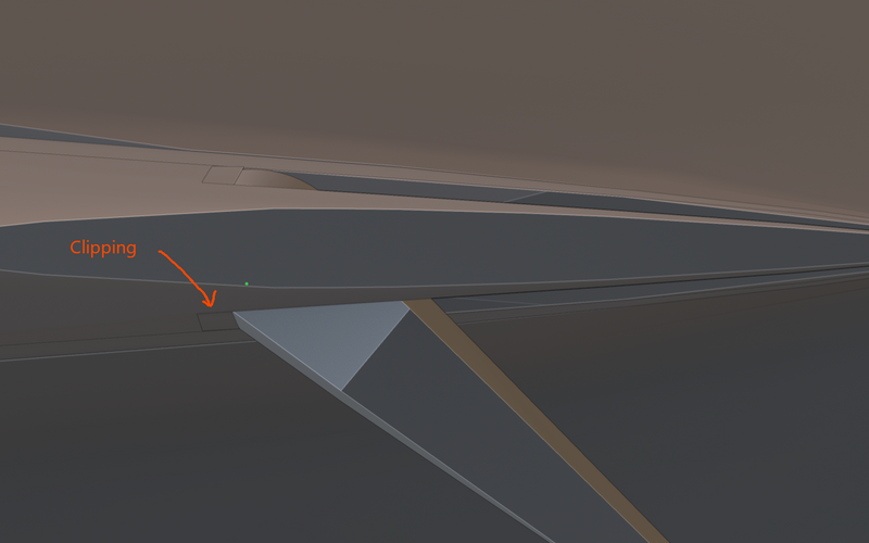
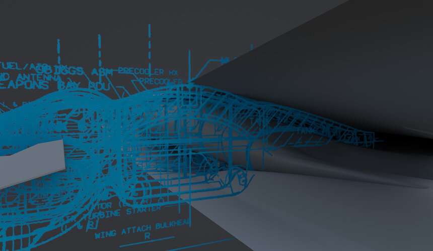
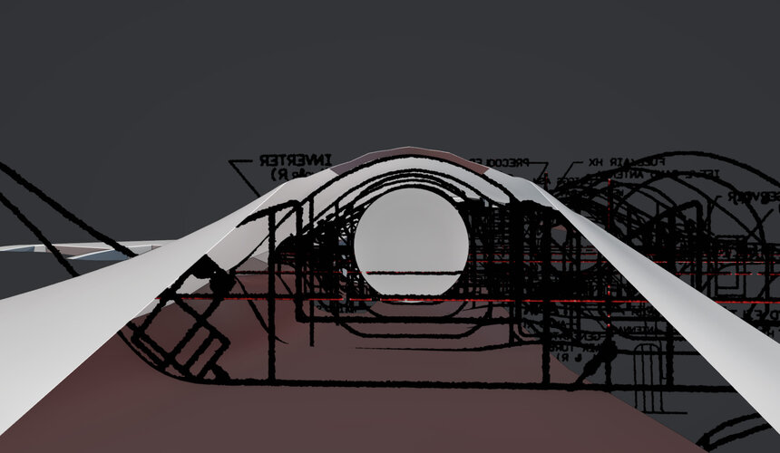
The particular issues: What were the deflection limits for the leading edge and the trailing edge flaps. And, how do they actually move, where is the rotational axis, how did they get rid of the gaps and seams that form when the surfaces deflect or the collision with the wing surface. (The screenshots will explain what I mean by this)
I know the ailerons do 40° up and down, but for the flaperons I am not so sure.
That is why I'm writing this post. Maybe somebody can help or knows how they'd solve this issue on the real bird.
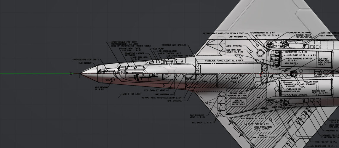
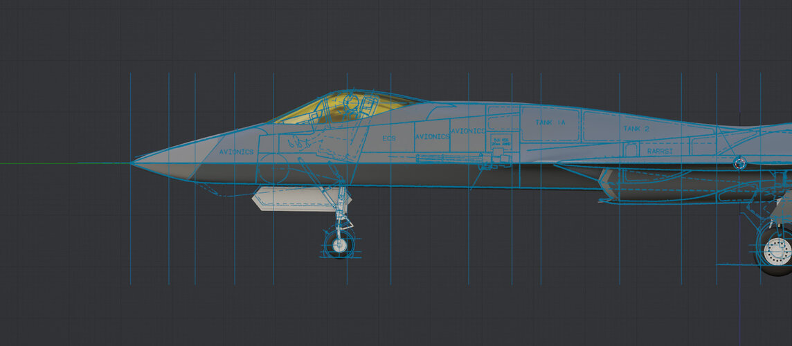
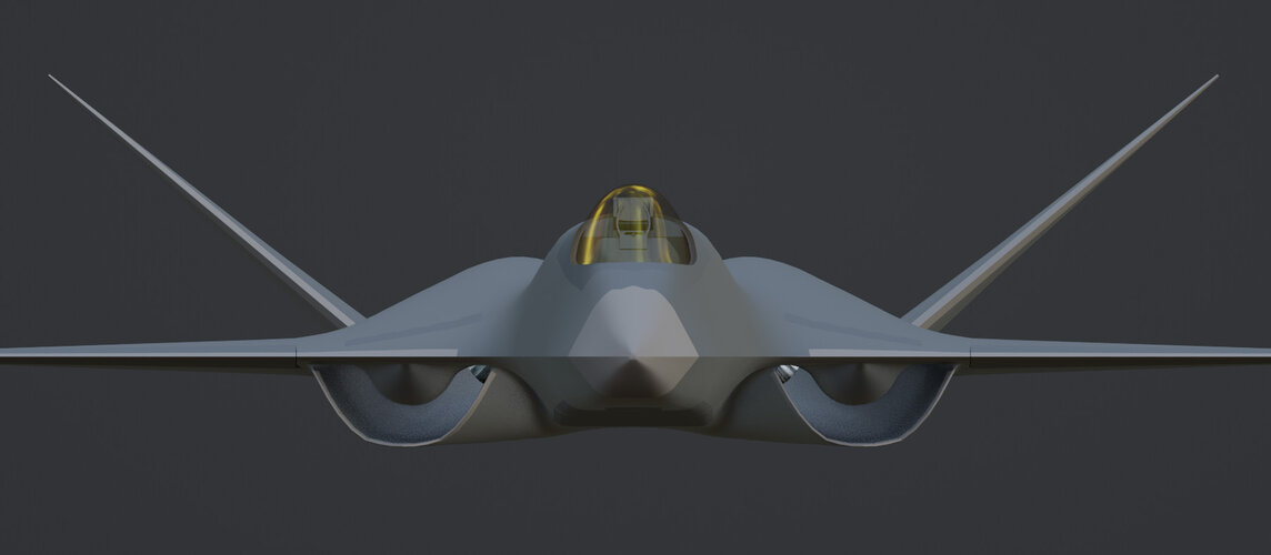
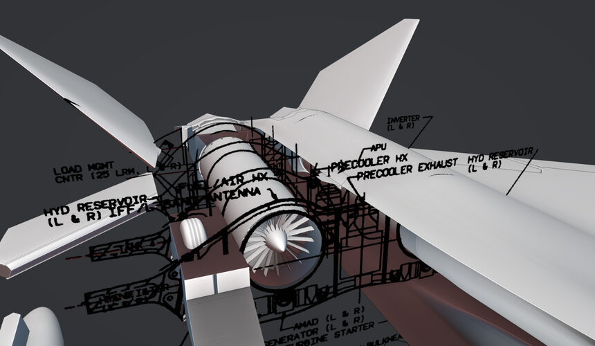
I have no real knowledge about aerospace engineering and aircraft manurfacturing so I don't know the lingo to look for in solving my questions. I will attach some screenshots of the issues for reference.

For the past couple years I have been working on a F-23A Model in Blender. I have been through a bunch of iterations and artistic license version of that particular aircraft including a two seat navalized version. However I have decided to create a more true to what could've been version and essentially re-did the model from scratch. I have had particular issues with all my iterations, when it comes to certain aspects of the model that are not well represented or explained in enough detail in any of the material I came across (I have the Paul Metz book and the Japanese picture book).
Those are the control surfaces.
The particular issues: What were the deflection limits for the leading edge and the trailing edge flaps. And, how do they actually move, where is the rotational axis, how did they get rid of the gaps and seams that form when the surfaces deflect or the collision with the wing surface. (The screenshots will explain what I mean by this)
I know the ailerons do 40° up and down, but for the flaperons I am not so sure.
That is why I'm writing this post. Maybe somebody can help or knows how they'd solve this issue on the real bird.
I have no real knowledge about aerospace engineering and aircraft manurfacturing so I don't know the lingo to look for in solving my questions. I will attach some screenshots of the issues for reference.


")