Flying Flapjacks

What I find weid is the lack of proper documentation on this aircraft. I am pretty sure I have seen something in an Xf5U article but can I find it, doh.....

 
I built this Boeing 390 some years ago and have flown it extensively. It is a large model, quite heavy, yet flies well with no bad characteristics. It is very easy to land as once an attitude for approach is set, it seems to hold this right down to flare. It is electric with actual counterrotating props and I can provide details if there is model interest.
Flyboyken, fantastic model; could you give some details about it, did you work from plans? How much power does it need versus similar sized models?
 
The pancake was unlike anything else flying at the time and might well have been shook in ways that were beyond the structural engineering knowledge of the day.
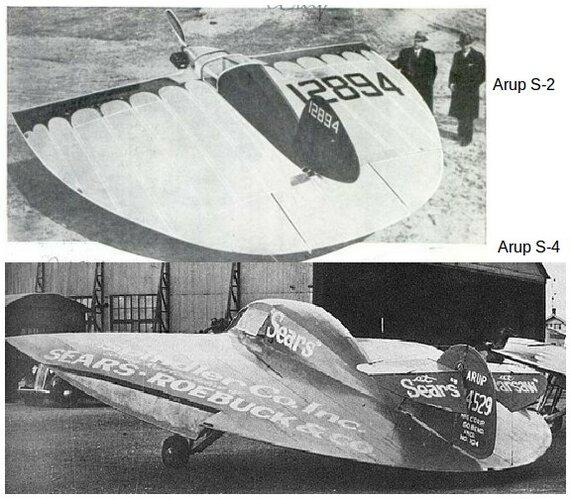
There was very much interest in and experience with such things, aside from Zimmerman's affectation for the props situated as they were, many had flown well.

See the Arup S-2 and S-4. Piloted by Glen Doolittle (the famous racer's cousin) 2 performed for NACA in ~'33, and Zimmerman was on the team that saw it fly.
It did not exhibit any abnormal drag in cruise; the huge wing-tip vortices are elective and temporary, in order to fly slow. It and many other types argue against the commonly held misconception that very-low aspect-ratio planes must be draggy.
Between the 2 planes, they flew several season at air shows, multiple pilots including novices and the founder, a podiatrist Dr Snyder took his wife and his son up in the 4. Frequently carrying adverts to pay for shop and hangar space. The S-3 was wrecked in arson at the shop space. The 2 & 4 apparently flew on until the age of the airframe grounded them. The 2 is being restored in a museum, the 4 is gone, scrapped at the start of the war after sitting outside.

"Radical Wings and Wind Tunnels" says that NACA tests showed very little difference to aerodynamic performance or flight, in the direction of prop rotation. It got its STOL abilities solely from the planform, not the props. They did not increase or really affect the cruise speed.
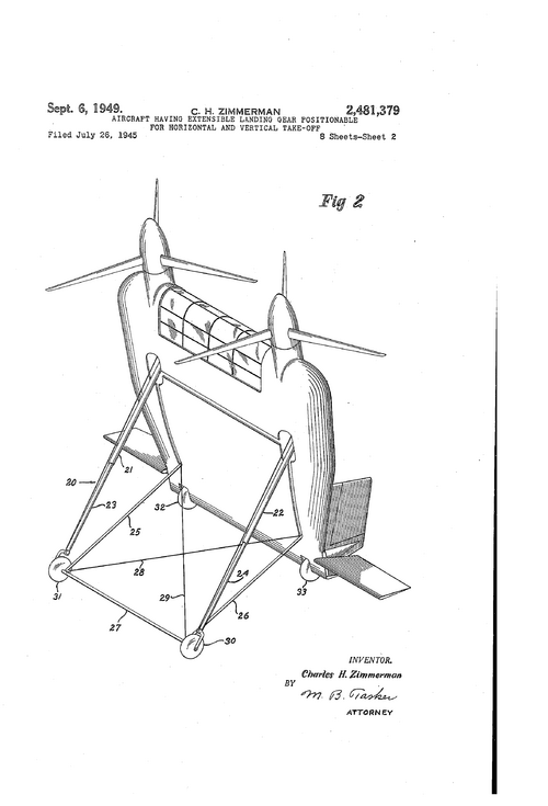
Zimmerman writes that he studied it at NACA and found the aspect ratio very close to the Arup maximized the vortex-driven "parachute lift" to gain 3-4x the lift at such slow speeds. He chose that planform specifically to maximize the vortices - it makes no sense to then try to counter them, knowing that it's not at all necessary.
He was specifically working towards a VTOL tail sitter, using the Arup planform as the slow speed high "A" starting point.

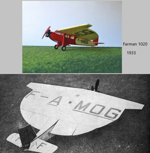
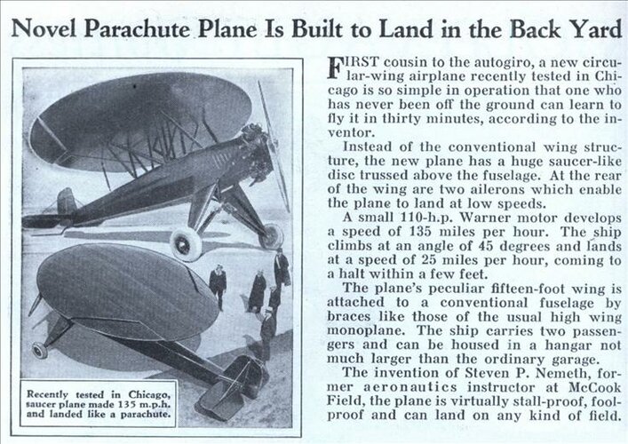
See also the Nemeth of the mid '30s and the similar Farman 1020. Faster than the planes which the fuselage came from, super-STOL with amazing climb rate, stall-spin proof.

Then there's the Eshelman "flounder" of '42. 130 hp, 180 mph, super-STOL
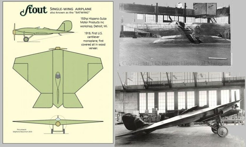
William Stout, US, 1918 "Batwing". Flew well, but pilots declared it a failure for total lack of visibility...
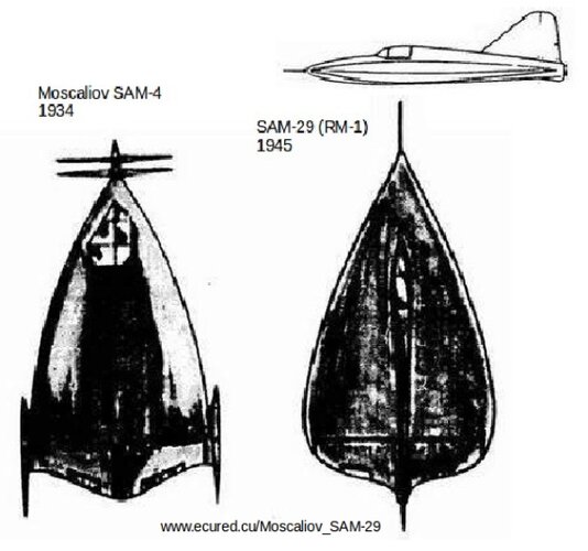
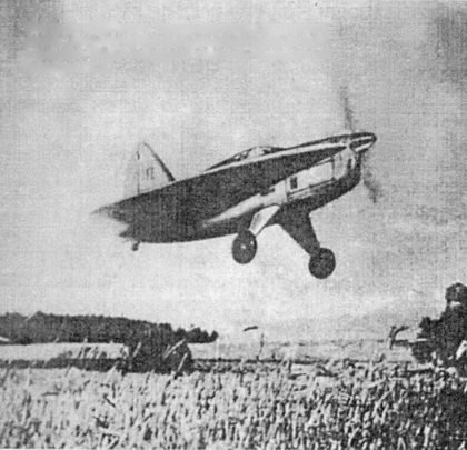
in '34, Moskalyev suggested a very-low aspect-ratio SAM-4 "Sigma" fast fighter, but got no support. In the '40s, in response to American successes (Vought and Eshelman?) he got the go-ahead for the SAM-9 Strela "Arrow" test plane, which was fast and super-STOL.
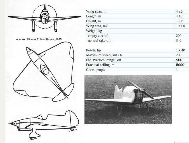
Nikolas Roland Payen, working for mr. Aubrun in the '30s, built the successful AP-10

All of these account also for the continued interest in wartime Germany for Arthur Sack's circular plane, though the AS-6 couldn't even "hop". Probably not enough A built into the landing gear for "parachute lift". Hand-launched models flew well.
 

Attachments

  • Arup.jpg
    Arup.jpg
    99.3 KB · Views: 115
  • Payen AP-10_06.jpg
    Payen AP-10_06.jpg
    102.3 KB · Views: 123
  • Moskalyev SAM-29.jpg
    Moskalyev SAM-29.jpg
    136.5 KB · Views: 93
  • Moskalyev SAM-9 Strela_03.jpg
    Moskalyev SAM-9 Strela_03.jpg
    37 KB · Views: 88
  • aero_Stout Batwing vampire_coomp.jpg
    aero_Stout Batwing vampire_coomp.jpg
    120.1 KB · Views: 94
  • Farman 1020 comp.jpg
    Farman 1020 comp.jpg
    105.2 KB · Views: 90
  • Nemeth_parachute_plane.jpg
    Nemeth_parachute_plane.jpg
    91.7 KB · Views: 97
  • Zimmerman  US2481379-1.png
    Zimmerman US2481379-1.png
    72.3 KB · Views: 94
Last edited:
I don't think anybody here is challenging that these things fly, and can fly fairly well. Nor that getting up speed, and reaching a regime where the vortices retreat to the tips, is more efficient that full-blown vortex lift at high AoA.
But all the experience with low-aspect-ratio jets, from Lippisch to Lockheed to Concorde to the F-35, is that such subsonic cruise is still less efficient than for a high-aspect-ratio wing. The F-111 and Tornado did not have their wings locked in the low-aspect-ratio rearward position, they swung wide for subsonic flight, and for very good reason; to fly more efficiently. It has, frankly, been an unquestionable tenet of fundamental aerodynamics theory and practical confirmation for well over a hundred years.
These low-speed disc-type wings, including a homebuilt cropped delta with a lousy faceted aerofoil, might be accepted as better than awful, but I see no evidence presented whatsoever to support the extraordinary claim that they defy the thousands of practical measurements made over the years and achieve anything like normal levels of efficiency.
 
The main difference, with regard to the above two posts is the speed regime. For a slow flying aircraft, one can gain good performance from the low aspect ratio wing, because while it's aerodynamic efficiency is low (See Aspect Ratio and Oswald Efficiency Factor) it can have a very efficient (thick) structure. So what you lose in aero efficiency you gain in structural efficiency. In fact, there was a very low aspect ratio Handley Page design that took advantage of this, but was never built. (It's on this site somewhere, the HP.126?) My understanding was that on short hops, city to city, it was competitive with standard designs. But on longer routes, it's lack of aerodynamic efficiency would have made it noncompetitive in the market. Also, the faster you go, the thinner a wing you want. So, that lives on in the form of the delta/ogive wing.
 
Although there'd be a weight penalty due machinery, would these have fared better with counter-rotating props ? Would have brought the bespoke prop diameter down to 'less than remarkable'...
 
the low aspect ratio wing, ... while it's aerodynamic efficiency is low (See Aspect Ratio and Oswald Efficiency Factor) it can have a very efficient (thick) structure.

Yes, this is of course one of the most celebrated characteristics of the steep delta wing. Lippisch especially long preferred this form, though it appeared most famously in the Vulcan V-bomber.
 
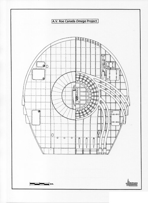
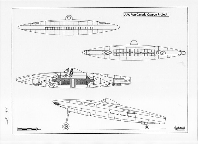
Cutaway Flying Saucer ???, author unknow an retouched by Motocar
The complex internal ducting reminds us of Avrocar. AVRO of Canada sketched dozens of possible supersonic variants, but only built a couple of simple VZ-9 prototypes to demonstrate hover performance. They proved unstable in hover and the project was cancelled.
 
Last edited:
Fly-by wire and 3D printed gas channels might allow a second chance. If a shuttle stack can launch without doing cartwheels-then modern tech could smooth out issues here. Remember-the very conventional F-16 may also have been beyond what Avro could do...and F-104 might have used fly-by-wire had it been available. I think people are put off from lenticular designs due to their retro looks-but that never stopped Musk.
 
If you were to revive it then surely you're talking a turbofan-based powerplant and electric puller-props that could gimball to give you active thrust-steering. But for what purpose? Flat designs would not be comfortable to ride in.
 
If you were to revive it then surely you're talking a turbofan-based powerplant and electric puller-props that could gimball to give you active thrust-steering. But for what purpose? Flat designs would not be comfortable to ride in.
Gimballing props is probably a bad idea. The Coriolis and related forces in moving an axis of rotation can be huge. You can get away with it on a small autogyro, but for higher-powered machines helicopter-style cyclic pitch control is the traditional route, and with careful design the actuators still require very little power.

But I am unclear what your turbofans are for; additional thrust, hybrid-power electricity generation, or what?
 
Jet Skimmer...

As it lacked the props to 'eat' tip vortices, would winglets have helped ??

Probably would not have cured sundry other failings, just wondering...
 
Jet Skimmer...

As it lacked the props to 'eat' tip vortices, would winglets have helped ??

Any thoughts must be speculative, but here's my two penn'orth:

Winglets could have helped a little, but only because they offered greater span to play around in. There are several standard things that can help:
  • Higher speed. For example the inefficiencies of the F-104 Starfighter wing disappeared once it was flying supersonic.
  • Greater span, whether achieved directly, or indirectly via winglets or outboard horizontal stabilizers (OHS). OHS may be seen on the Vought designs and on the short-span SpaceShips One, Two and Three.
  • Tailoring the aerofoil across the span to achieve a bell-like lift distribution curve. This minimises the induced drag from tip vortices, and also minimises structural stresses, at the expense of slightly increased area. Typically the tips are washed-out with reduced, even slightly negative AoA, and the aerofoil is thinned down and/or given leading-edge droop. This is a classic solution even if you have a tail and is evident on many types, such as the Supermarine Spitfire.
  • Introducing a cambered aerofoil in place of the symmetrical ones usually chosen for these flapjacks. This improves the efficiency of the whole wing, but impacts stability. The symmetrical type is stable (or neutral) in pitch, whereas a cambered aerofoil is unstable. The tailoring described above, especially tip washout, can restore any lost stability. This was Reimar Horten's approach. Another compromise is to adopt positive camber for the main area but negative camber for the rear section; this was favoured by GTR Hill, but for a flapjack it loses the advantages of spanwise tailoring.
A more off-the-wall approach, already mentoned by me above (so I have edited this paragraph down), is Kitchen's flat annular wing, not so much a flapjack as a doughnut someone has stood on. To my knowledge, this particular configuration has never been studied in any depth. However various other joined-wing variations have been proposed in more recent years, typically for jet transports where short span was less of an issue.
 
Last edited:
A more off-the-wall approach, already mentoned by me above (so I have edited this paragraph down), is Kitchen's flat annular wing, not so much a flapjack as a doughnut someone has stood on.
Perhaps a layered approach to lenticular designs. A standard, modernized Avrocar approach with one engine unit—-but a torus like intake feeding into a second jet once airborne. The exhaust terminates into something that looks a bit like a linear aero spike but with a ramjet “collar” faired in…with perhaps a vertical fin(s) to bite into the slipstream for thrust vectoring rudders.
 
A standard, modernized Avrocar approach with one engine unit
I suspect the Avrocar was such an unstable failure because it had a cambered cross-section and was therefore aerodynamically unstable in forward flight. Its hovering problems were also in large part down to the same ignorance and lack of a skirt that bedevilled Cockroft's first hovercraft. Combine the two issues with an utter lack of fly-by-wire tech and, once it began to pick up any kind of forward speed, whoops!
Its lift-cum-propulsion-cum-control system all round the rim was in some ways analogous to a helicopter, though with lower mass flow and hence lower efficiency - not that helicopters are exactly renowned for their efficiency anyway, while such ducted or blown systems have seldom in practice achieved the thrust levels obtained in the lab and usually proved to need such powerful, large and heavy engines as to defeat any other advantages.
It would be interesting to stick a truly symmetrical, zero-camber body around the lift fan from an F-35C, forget hovercraft and high-speed flight modes, and see if the rim system can at least offer helicopter-like performance and get one-up on the Moller Volantor. That might even offer useful applications, such as safe VTOL close to vertical surfaces like buildings, cliffs and sinkholes.
 
Last edited:
To prevent Twilight Zone Movie tragedies. I would want a separate jet for forward flight.

Now, one of the things I saw was a drone on wheels that could “drive” up a wall…small thing though…I don’t know that if it can scale…
 
Cutaway Flying Saucer ???, author unknow an retouched by Motocar
The complex internal ducting reminds us of Avrocar. AVRRO of Canada sketched dozens of possible supersonic variants, but only built a couple of simple VZ-9 prototypes to demonstrate hover performance. They proved unstable in hover and the project was cancelled.
Late in 1951 John Frost made a proposal for a proof-of-concept saucer-like flying vehicle. Early in 1952 the A.V. Roe Special Projects Group was formed to investigate the Frost ideas.

On February 7, 1952, the Group distributed an internal document titled ‘Description and Thoughts on the Turbo Disc’ (a simple gas turbine halfway between a ram-jet engine and centrifugal engine), Frost also submitted the design to the engineering department of McGill University.

The radial-flow turbojet designed by the Frost team had twenty feet of diameter, 42,000 lbf minimum thrust at low pressure and an outstanding power-to-weight ratio of 1.73 to 1.

The horizontal Pelton-wheel turbine had a large multi-stage centrifugal compressor with the rotor blades mounted on the inner disc ring and the stator blades in the outer disc ring. The separate combustion system consisted of several combustion chambers with individual burners and nozzle guide vanes distributed in a radial pattern between the ribs of the vehicle.

This work led to the first design named Omega project, with elliptical planform, 36 ft wingspan, 40 ft overall length and 1 to 7 aspect ratio. It was proposed to control the vehicle by altering the direction of thrust forces.

The vehicle had twenty air-intake slots mounted in the nose, the new pancake engine was designed as an integral part of the airframe and the jet thrust exited from around the entire rim of the engine.

About three-fifths of the jet exhaust flow through a multiple jet-pipe assembly that direct the flow of gases in a rearward direction from the sides of the airframe for propulsion and the remainder is ejected from the trailing edge through ten deflector vanes comprising elevons and trimmers providing control in yaw, roll and pitch.
 

Attachments

  • 252.jpg
    252.jpg
    1.2 MB · Views: 270
  • 253.jpg
    253.jpg
    746.8 KB · Views: 304
A standard, modernized Avrocar approach with one engine unit
I suspect the Avrocar was such an unstable failure because it had a cambered cross-section and was therefore aerodynamically unstable in forward flight. Its hovering problems were also in large part down to the same ignorance and lack of a skirt that bedevilled Cockroft's first hovercraft. Combine the two issues with an utter lack of fly-by-wire tech and, once it began to pick up any kind of forward speed, whoops!
Its lift-cum-propulsion-cum-control system all round the rim was in some ways analogous to a helicopter, though with lower mass flow and hence lower efficiency - not that helicopters are exactly renowned for their efficiency anyway, while such ducted or blown systems have seldom in practice achieved the thrust levels obtained in the lab and usually proved to need such powerful, large and heavy engines as to defeat any other advantages.
It would be interesting to stick a truly symmetrical, zero-camber body around the lift fan from an F-35C, forget hovercraft and high-speed flight modes, and see if the rim system can at least offer helicopter-like performance and get one-up on the Moller Volantor. That might even offer useful applications, such as safe VTOL close to vertical surfaces like buildings, cliffs and sinkholes.
On April 2, 1955, the USAF signed Avro contract Nº AF33 (600) 30161 for the Project 1794. The contract specified analytical investigations to determine the performance capabilities of a flat VTOL all-wing aircraft of circular planform employing jet control. The areas for analysis were defined as:

Air Cushion Effect

Stability of multi-engine configuration

Air intake and gas exhaust system test

Aircraft performance, stability, and control

Radial-flow engine feasibility


Aerodynamic tests with 1/6 and 1/40 scale models were conducted at Wright-Patterson and M.I.T. wind tunnel facilities. Tests of speed, transition control, pitch control, jet thrust, intake flow, ground position and angle of attack were completed on June 14, 1956.

An attempt was made to theoretically calculate the Ground Effect, but theory does not explain observations sufficiently accurately and no tests of radial-flow engine feasibility have been carried at the end of the program.

A low-speed research vehicle was proposed to investigate stability, control systems and Air Cushion Effect, before development of a supersonic operational aircraft.

This planned prototype had 21 ft 6 in (6.55 m) of diameter, 4 ft (1.2 m) height and was powered by eight radially mounted Armstrong-Siddeley Viper A.S.V. 8 turbojets, with 4,188 lbs. thrust each, radial diffuser ducts and Coanda peripheral ring.

The final development aircraft had a turbo-ramjet propulsion system with one Lundström compressor/turbine powered by three Viper A.S.V. 5 turbojets, a single-stage axial impeller and 144 flame tubes. The planned aircraft had 35.3 ft (10.75 m) of diameter, 5.35 ft (1.63 m) height, Mach 3.0 top speed and 94,000 ft ceiling.

On November 4, 1955, Avro Canada proposed the PV.704 project to develop the radial-flow engine to eliminate any delays in the development of the Project 1794 propulsion system.

In the PV.704 power plant the incoming air sucked through the upper and lower intakes was fed into the hollow cylinder of Lundström turbo-rotor, pressurized by means of the four-stage upper and lower impellers and directed towards the peripheral air intakes of six radially mounted Viper A.S.V. 8 turbojets. Partial flow of compressed air proceeds radially to 24 peripheral combustion chambers and finally expelled through 96 flight control shutters.

On September 26, 1957, the U.S. Army approached Avro with a request for an Air Cushion Effect ‘flying jeep’, by March 1958 the Special Projects Group designed a modest subsonic circular aircraft called Avrocar.

Thrust of their three turbojets were used for turning the Turborotor, a 124 blades fan with 5 ft of diameter, to provide vertical lift. Partial thrust was ducted to periphery flaps and exhaust nozzles which provided stability and control.

In May 1958, USAF signed contract AF33 (600) 37496 for the construction of the mock-up and one proof-of-concept demonstrator. A second prototype was commissioned in March 1959.

On October 7, 1959 tethered flight tests of the noisy prototype VZ-9AV (59-4975) indicated that one-third of the thrust was being lost to exhaust inefficiencies. This meant the aircraft would be incapable of hovering out the Ground Effect.

With enough power even a brick can fly, but the Avrocar never had the power to do so. Thrust losses required a complete re-design, a costly decision that crippled the entire program.

During the first free flight conducted in May 1959 the Avrocar never exceeded one meter off the ground, but the lack of control flight was its undoing.

It was discovered that the prototype was inherently unstable in forward flight, with rapid and unpredictable swings in pitch and roll axes, a control problem called ‘hub capping’.

The development contract was completed in December 1961 and the project was discontinued.

VZ-9AV technical data

Diameter: 18 ft (5.49 m), thickness: 3.6 ft (1.1 m), height: 7.7 ft (2.34 m), wing surface: 254 sq. ft, estimated top speed: 300 mph (482 kph), estimated ceiling: 9,840 ft (3,000 m), empty weight: 2,992 lb. (1,360 kg), max weight: 5,639 lb. (2,563 kg), power plant: three Continental J69-T-9 turbojets with 927 lb. static thrust each, estimated range: 25 miles with ten-minutes hovering capability.
 
The planned aircraft had 35.3 ft (10.75 m) of diameter, 5.35 ft (1.63 m) height, Mach 3.0 top speed and 94,000 ft ceiling.

I think "planned" is a little over-optimistic. "Dreamed-of" would be more accurate. We should not forget Pye Wacket, the US project for a Mach 3+ lenticular air-to-air missile, contracted to Convair:
https://www.secretprojects.co.uk/threads/afsc-secret-project-1168-code-named-pye-wacket.3814/Wikipedia says that the lenticular design was expected to have good control characteristics at extreme AoA, a suggestion which baffles me and I must wonder whether the mistake is theirs or the USA's; perhaps it was just less appalling than a wedge at higher AoA than the taper angle, and NASA knew of none better at that time. Of course it didn't, nor at any other speed.

I seem to recall once seeing some photos on the NASA web site or similar, of later wind tunnel models which had grown a stabilising twin-boom tail (which would also have been unhappy at extreme AoA), but I can't find them now, so maybe my memory is failing me.

I suppose the main difference between the dreamed-of Avrocar and Pye Wacket was whether the payload was a pilot or a nuke. That and the Avrocar's rim drive.

Later NASA developed some rather more practical lifting bodies, which helped pave the way for the Shuttle.
 
Last edited:
"...grown a stabilising twin-boom tail..."

Akin Virgin Galactic's whatsit ??
 
"...grown a stabilising twin-boom tail..."

Akin Virgin Galactic's whatsit ??
Yes and no. I recall it as just a conventional fixed pair of booms with a stabilizer across the middle. The outboard horizontal stabilizers (OHS) of SpaceShips One/Two/Three are a bit different, though both designs are variations on the same fundamental solution to aerodynamic stability, when you have a rocket exhaust where you wanted to put the tail support structure.
But as I said, don't trust my memory on Pye Wacket
 
Bono's saucer also looked to have two tailfins. I could see equipment on a racetrack rim.
 
Bono's saucer also looked to have two tailfins. I could see equipment on a racetrack rim.
Bono briefly studied a lenticular spaceplane. There's a note and illustration at http://www.astronautix.com/b/bonosaucer.html
I don't know whether it launched vertically, but presumably it landed horizontally and so qualifies as a "flying flapjack", at least during re-entry and landing. Whatever its flight regime, it turned out less efficient than a conventional space rocket.
 
That thing was an HLLV-not just a spaceplane. What still draws my interest is ultra-low wing loading-and the potential for very wide, flat payloads that can be irised out even wider-like Solar Powersats.
 
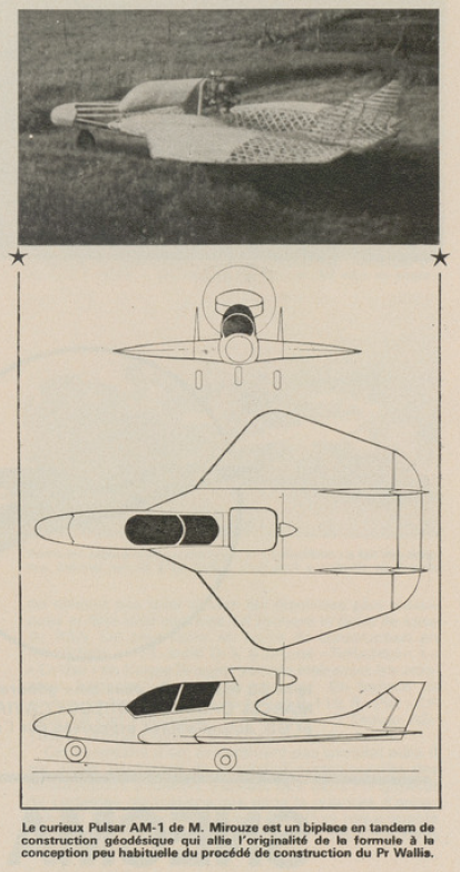
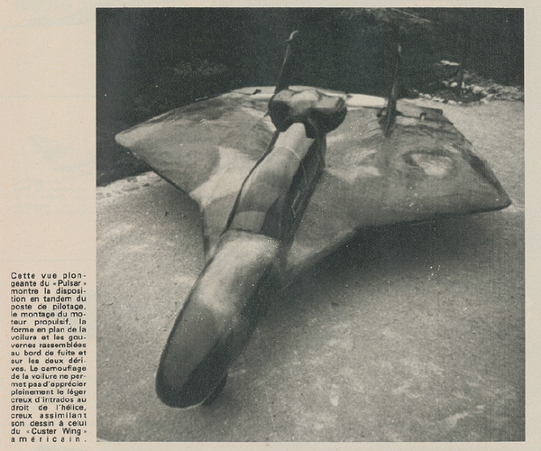
The formula has also been tested by Alain Mirouze, in France, in the late 70's and 80's.
Without much success.
The "Pulsar" performed her first flight on November 11th, 1974.
The "Pulsar 2" just some hops in 1984

From Aviation magazine 1974.
From Aviation magazine 1975.
 

Attachments

  • 50.png
    50.png
    793.4 KB · Views: 246
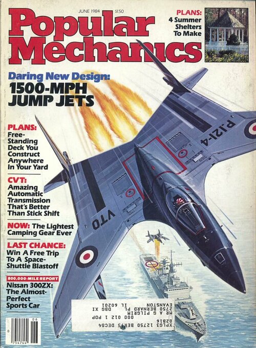
This was the B.Ae P.1214, effecively a design study for the P.1216. Mike Pryce includes some info on it in his book on the latter (published by our Blue Envoy). It is not really a flapjack so much as a forward-swept wing with twin tailbooms and a deep centre section. In the drawing Mike reproduces, the trailing edge is moved further forward to reduce problems of rear jet efflux in the vertical/transition modes.
Here's the Popular Mechanics edition with the article: https://ia601302.us.archive.org/9/items/PopularMechanics1984/Popular_Mechanics_06_1984.pdf
 
Could any 'Flying Flapjack' STOL have been crafted in time for the Atlantic convoys' protection instead of those near-kamikase 'HurriCats' ? So before the 'escort carriers' finally came off slip-ways ??

If STOLs only needed two tennis-courts and an anti-skid net to 'land-on', they'd change the paradigm...

Yes, the 'What-If' of such 'Flying Saucers' briskly beating up startled Condors and strafing U-Boots appeals...

FWIW, an uncle tended RADAR aboard a sub-hunter working out of Liverpool. As depth-charging and/or ramming would reliably derange the oft-cantankerous [REDACTEDS], they logged no kills, but many 'assists'...
 
Maybe?

That would have been a 1980s or 1990s development, IMO.
It was first done in the 1950s on standard planes, the A5 Vigilante had it as well as the F4.

So it might have been possible.

Issue would have been getting the money and interest to do so.
 
Maybe?

That would have been a 1980s or 1990s development, IMO.
Oh, absolutely. I wasn't considering it as a 1940-50s era technology, though blown flaps and boundary layer control didn't take too long to emerge after that. I was considering it more in the context of a later ground attack flapjack for use by someone like the US Marines.
 
Looks like a very useful platform for an unmanned AWACS or umnanned subhunting mission.
 
It was first done in the 1950s on standard planes, the A5 Vigilante had it as well as the F4.
That's just flap blowing, which is very different from seeing a stream of blown air as a winglet or control surface all by itself.

IIRC that wasn't visualized until the F-18 HARV in the early 1990s.


Looks like a very useful platform for an unmanned AWACS or umnanned subhunting mission.
I've been very surprised that none of the companies working for the DARPA TERN and the USN follow-on program haven't used a Flapjack airframe.
 
Back
Top Bottom